![]()
 Installation Instructions
for use by heating contractor
EA1 Extension Module
for programmable inputs and outputs
 Certified as a component part for Viessmann boilers
Product may not be exactly as shown
IMPORTANT
Read and save these instructions for future reference.
Safety
Safety, Installation and Warranty Requirements
Please ensure that these instructions are read and understood before commencing installation. Failure to comply with the instructions listed below and details printed in this manual can cause product/property damage, severe personal injury, and/or loss of life. Ensure all requirements below are understood and fulfilled (including detailed information found in manual subsections).
Product documentation
Read all applicable documentation before commencing installation. Store documentation near boiler in a readily accessible location for reference in the future by service personnel. For a listing of applicable literature, please see section entitled “Important Regulatory and Safety Requirements”.
Licensed professional heating contractor
The installation, adjustment, service and maintenance of this equipment must be performed by a licensed professional heating contractor. Please see section entitled Safety and “Important Regulatory and Installation Requirements”.
Advice to owner
Once the installation work is complete, the heating contractor must familiarize the system operator/ ultimate owner with all equipment, as well as safety precautions/requirements, shutdown procedure, and the need for professional service annually before the heating season begins.
Warranty Information contained in this and related product documentation must be read and followed. Failure to do so renders the warranty null and void.
Important Precautions
Important Regulatory and Installation Requirements
Approvals
Viessmann boilers, burners and controls are approved for sale in North America by CSA International.
Codes
The installation of this unit shall be in accordance with local codes. In the absence of local codes, use:
– CSA C22.1 Part 1 and/or local codes in Canada
– National Electrical Code ANSI/NFPA 70 in the U.S.
Always use latest editions of codes.
The heating contractor must comply with the Standard for Controls and Safety Devices for Automatically Fired Boilers, ANSI/ASME CSD-1 where required by the authority having jurisdiction.
Working on the equipment
The installation, adjustment, service, and maintenance of this product must be done by a licensed professional heating contractor who is qualified and experienced in the installation, service, and maintenance of hot water boilers.
There are no user serviceable parts on the boiler, burner, or control.
Power supply
Install power supply in accordance with the regulations of the authorities having jurisdiction or, in absence of such requirements, in accordance with National Codes.
Viessmann recommends the installation of a disconnect switch to the 120V power supply outside of the boiler room.
Ensure main power supply to equipment, the heating system, and all external controls have been deactivated. Close main oil or gas supply valve. Take precautions in both instances to avoid accidental activation of power during service work.
Please carefully read this manual prior to attempting installation. Any warranty is null and void if these instructions are not followed.
For information regarding other Viessmann System Technology componentry, please reference documentation of the respective product.
We offer frequent installation and service seminars to familiarize our partners with our products. Please inquire.
The completeness and functionality of field supplied electrical controls and components must be verified by the heating contractor. These include low water cut-offs, flow switches (if used), staging controls, pumps, motorized valves, air vents, thermostats, etc.

![]() WARNING
WARNING
Turn off electric power supply before servicing. Contact with live electric components can cause shock or loss of life.
General Information
About these Installation Instructions
Take note of all symbols and notations intended to draw attention to potential hazards or important product information.
![]() WARNING
WARNING
Warnings draw your attention to the presence of potential hazards or important product information.
- Indicates an imminently hazardous situation which, if not avoided, could result in death, serious injury or substantial product/property damage.
![]() CAUTION
CAUTION
Cautions draw your attention to the presence of potential hazards or important product information.
- Indicates an imminently hazardous situation which, if not avoided, may result in minor injury or product/property damage.
IMPORTANT
- Helpful hints for installation, operation or maintenance which pertain to the product.
- This symbol indicates to note additional information
 This symbol indicates that other instructions must be referenced.
Installation
Mounting the Extension Kit  Extension kit for installation on a wall
- Loosen the retaining screws from the extension kit encloser (do not remove) .
- Remove cover and set aside.
- Mount the extension module enclosure to the wall using the supplied hardware.
- Install the cover.
Components:
- EA1 extension module
- KM BUS plug 145
- Power cord pre-wired to plug 40
- Digital inputs DE1, DE2 and DE3 plugs
- 0-10VDC input plug
- Programmable output plug 157
- Accessory power plug 40 A
Connections
Overview of Electrical Connections Legend
| DE1 | Digital input 1 |
| DE2 | Digital input 2 |
| DE3 | Digital input 3 |
| 0 – 10 V | 0 – 10 V input |
| 40 | Power supply |
| 40A | Power supply for additional accessories |
| 157 | Programmable output |
| 145 | KM BUS to the control unit |
| A | Extension EA1 |
| F1 | Fuse |
![]()
![]() CAUTION
CAUTION
The electronic modules are static sensitive. To avoid damage caused by static discharge, follow Electro-Static Discharge safety procedures.
Note: Apply strain relief to all on-site cables. Close any unnecessary knock-outs with cable entries (not cut open).
Connecting Digital Inputs
The following functions can be connected alternatively:
- External heating program changeover for each heating circuit
- External blocking
- External blocking with central fault message
- External demand with set flow temperature
- Central fault message
- Brief operation of the DHW circulation pump
The hooked-up contacts must correspond to protection class II.
Function assignment of inputs DE1 to DE3
Select the input functions by means of the codes on the boiler control unit.
Complete description of the coding addresses:
![]() Service instructions for boiler or control unit
Service instructions for boiler or control unit
| Coding address |
Control unit | |
| Vitotronic, type H… | Vitotronic, type G… | |
| Input DE1 | 3A | 5d |
| Input DE2 | 3b | 5E |
| Input DE3 | 3C | 5F |
Subject to function and digital input selected for the respective function, the following codes need to be changed at the boiler control unit:
| Function | Setting Code 3A, 3b, 3C (Vitotronic, type H … ) Code 5d, 5E, 5F (Vitotronic, type G …) |
| No function | 0 |
| Heating program changeover | 1 |
| External demand with set flow temperature | 2 |
| External blocking | 3 |
| External blocking with fault message input | 4 |
| Fault message input | 5 |
| Brief operation, DHW circulation pump | 6 |
Assigning the heating program changeover function to the
heating circuits
Assign the heating program changeover function for the respective heating circuit via code d8 at the boiler control unit:
- Changeover via input DE1: Code d8:1
- Changeover via input DE2: Code d8:2
- Changeover via input DE3: Code d8:3
- Select the effect of the heating program changeover via code d5
- Set the duration of the changeover via code F2
Effect of the external blocking function on the pumps
- Select the effect on the internal boiler circulation pump (Vitotronic, type H …) with code 3E
- Select the effect on the respective heating circuit pump with code d6
- Select the effect on the circulation pump for DHW tank heating (Vitotronic, type H …) with code 5E
Effect of the external demand function on the pumps
- Select the effect on the internal boiler circulation pump (Vitotronic, type H …) with code 3F
- Select the effect on the respective heating circuit pump with code d7
- Select the effect on the circulation pump for DHW tank heating (Vitotronic, type H …) with code 5F
Set flow temperature for external demand
- The set flow temperature can be selected with code 9b
Runtime of the DHW recirculation pump
Set the runtime:
- Vitotronic, type H …: Code 3d
- Vitotronic, type G …: Code 12
![]() Refer to the boiler Service Instructions
Refer to the boiler Service Instructions
Connecting the Analog Input 0-10V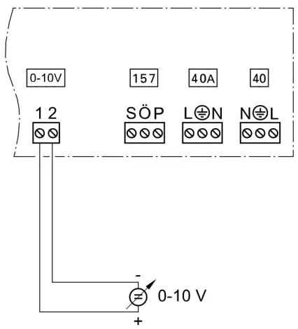 The 0 – 10V hook-up provides an additional set boiler water temperature:
0 – 1V seen as “no default set boiler water temperature”
1V ![]() set value 50°F (10°C)
set value 50°F (10°C)
10V ![]() set value 212°F (100°C)
set value 212°F (100°C)
On the Vitotronic, type G … the range of the set value default can be changed with code 1E:
1V ![]() set value 86°F (30°C)
set value 86°F (30°C)
10V ![]() set value 248°F (120°C)
set value 248°F (120°C)
Connecting the KM BUS to the Boiler Control Unit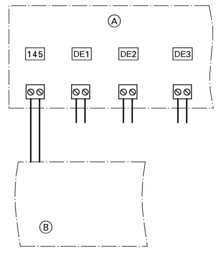 Legend
A Extension EA1
B Connection area of boiler control unit
![]() Boiler control unit installation and service instructions
Boiler control unit installation and service instructions
Connecting the KM BUS to the Extension Modules Legend
A Boiler control unit
B Extension kit for heating circuit with mixing valve M2
C Extension kit for heating circuit with mixing valve M3
D Extension AM1, EA1 and/or solar control module, type SM1
Connecting a Circulation Pump or a Fault Message Facility Legend
A Circulation pump or fault message facility
The following components can be connected to plug 157:
- Pump speed reduction function
or - DHW re-circulation pump
or - Fault message facility
Rated voltage (max):………………… 120V
Rated current (max):……………….. 2 A~
Function assignment
Select the function of output 157:
- Vitotronic, type H …: Code 36
- Vitotronic, type G …: Code 5C
If a digital input is used as fault message input, the connected fault message facility is switched on when a fault occurs.
![]() Refer to the boiler Service Instructions
Refer to the boiler Service Instructions
If the relay of output 157 is switched, contact P-Ö is open.
If a fault occurs at extension EA1 or communication is interrupted, contact P-Ö is closed.
Note: If a fault message facility is connected, this will be activated briefly when the system starts.
Power Supply
 Direct power supply
![]() WARNING
WARNING
Incorrectly executed electrical installations can result in injuries from electrical current and in equipment damage.
Connect the power supply (see page 2) and implement all grounding measures (e.g. RCD circuit) in accordance with the following regulations:
- In Canada all electrical wiring is to be done in accordance with the latest edition of CSA C22.1 Part 1 and/or local codes. In the U.S. use the National
- Electrical Code ANSI/NFPA 70. The heating contractor must also comply with both the Standard for Controls and Safety Devices for Automatically Fired Boilers, ANSI/ASME CSD-1, and the Installation Code for Hydronic Heating Systems, CSA B214-01, where required by the authority having jurisdiction.
- Connection requirements specified by your local power supply utility
- Protect the power cable with max. 15A
![]() WARNING
WARNING
The absence of component grounding in the system can lead to serious injury from electrical current if an electrical fault occurs. Connect the appliance and pipework to the equipotential bonding of the building in question.
Isolators for non-grounded conductors
- The mains isolator (if installed) must simultaneously isolate all non-grounded conductors from the mains with a minimum contact separation of 3 mm.
- If no mains isolator is installed, all nongrounded conductors must be isolated from the mains by the upstream circuit breaker with a minimum contact separation of 3 mm.
![]() WARNING
WARNING
Incorrect core allocation can result in serious injury and damage to the appliance.
Never interchange cores “L” and “N”.
![]() CAUTION
CAUTION
An incorrect phase sequence can cause damage to the appliance. Check for phase equality with the power supply connection of the control unit.
Connection and Wiring Diagram Legend
| DE1 | Digital input 1 |
| DE2 | Digital input 2 |
| DE3 | Digital input 3 |
| 0 – 10 V | 0 – 10 V i n p u t |
| A | Extension EA1 |
| 40 | Power supply |
| 40 A | Power supply for additional accessories |
| 157 | Fault message facility/Feed pump/DHW circulation pump (floating) |
| 145 | KM BUS to the control unit |
Additional Information
Specifications
| Rated voltage | 120 V~ |
| Rated frequency | 60 Hz |
| Rated current | 2A |
| Power consumption | 1.5W |
| Protection class | I |
Permissible ambient temperature
| During operation | 32 to 104°F (0 to 40°C) |
| During storage and transport | -4 to +149°F (–20 to +65°C) |
| Rated breaking capacity, floating output 157 | 2A 120V~ |
Technical information subject to change without notice.
![]() Printed on environmentally friendly (recycled and recyclable) paper.
Printed on environmentally friendly (recycled and recyclable) paper.
Scan for digital copy of this document http://www.vitoteam.com/docs/?id=5774470&doc=II&s=EA1&src=QR
![]() Viessmann Manufacturing Company (U.S.) Inc.
Viessmann Manufacturing Company (U.S.) Inc.
45 Access Road
Warwick, Rhode Island · 02886 · USA
TechInfo Line 1-888-484-8643
1-800-288-0667 · Fax 401-732-0590
www.viessmann-us.com
info@viessmann-us.com
Viessmann Manufacturing Company ULC
750 McMurray Road
Waterloo, Ontario · N2V 2G5 · Canada
TechInfo Line 1-888-484-8643
1-800-387-7373 · Fax 519-885-0887
www.viessmann.ca
info@viessmann.ca
Documents / Resources
 |
VIESSMANN EA1 Extension Module [pdf] Installation Guide 5774 470 - 03, EA1 Extension Module, EA1, Extension Module, Module |