![]() Installation Guide
Installation Guide
Humidity
HD2 Protocol Series Duct Mount Humidity Sensors
 HD2 Protocol Series
Duct Mount Humidity Sensors
![]() Veris Industries
Veris Industries
Stratford Park 5
Telford TF3 3BL
United Kingdom
![]() WARNING
WARNING
![]() HAZARD OF ELECTRIC SHOCK, EXPLOSION OR ARC FLASH
HAZARD OF ELECTRIC SHOCK, EXPLOSION OR ARC FLASH
- Apply appropriate personal protective equipment (PPE) and follow safe electrical work practices. See NFPA 70E or CSA Z462.
- This equipment must only be installed and serviced by qualified electrical personnel.
- Turn off all power supplying this equipment before working on or inside equipment.
- Always use a properly rated voltage sensing device to confirm power is off.
- Replace all devices, doors and covers before turning on power to this equipment.
Failure to follow these instructions can result in death, serious injury or equipment damage.
This product is intended for use in HVAC and building environmental control applications.
It is not intended for direct medical monitoring of patients.
Read and understand these instructions before installing this product.
The installer is responsible for all applicable codes.
If this product is used in a manner not specified by the manufacturer, the protection provided by the product may be impaired. No responsibility is assumed by the manufacturer for any consequences arising out of the use of this material.
Product Overview
HD2 Protocol Series Humidity Sensors provide an ideal solution for measuring relative humidity in a wide range of conditions. All models are equipped with a thin-film capacitive humidity sensor that is easy to replace in the field. A solid state temperature sensor provides high-accuracy measurements.
HD2 is an all-in-one device combining humidity and temperature sensing. Intended for duct mount applications, the device ensures a building’s optimum temperature and humidity levels, resulting in greater energy efficiency.
Each device is an active sensor that converts a humidity or temperature measurement into a BACnet MS/TP or Modbus RTU output.
Different models are available based on application requirements for lower-cost installations.
HD2 is available with an LCD display option on select models (see Product Identification section below).
Product Identification
 Note: Replaceable RH and temperature modules available to be ordered separately per table below.
Replaceable RH Elements & Temperature and Humidity Calibration Modules
|
Model |
Description |
| HS1N | Replaceable RH sensor, 1% with NIST certificate |
| HS2N | Replaceable RH sensor, 2% with NIST certificate |
| HS2X | Replaceable RH sensor, 2% |
| TS2* | Replaceable temperature module with 2-point calibration certificate |
| THS2* | Replaceable temperature and humidity module with 2-point calibration certificate |
*For temperature transmitter models only.
Note: For instructions on installing replaceable elements, see Z207941, Replacement Humidity and Temperature Sensors Installation Guide.
Specifications
|
OPERATING / STORAGE ENVIRONMENT |
|
| Operating Temp. Range | -35 to 60 °C (-31 to 140 °F)* |
| Operating Humidity Range | 0 to 95% RH (non-condensing)* |
| Storage Temp. Range | -35 to 70 °C (-31 to 158 °F)* |
| Storage Humidity Range | 0 to 95% RH (non-condensing) |
| Power Supply | 20 to 30 Vdc, 24 Vac, 50 to 60 Hz |
| Output | BACnet MS/TP, Modbus RTU |
| Power Consumption | See Maximum Power Consumption table, page 8 |
| Tube Length | 200 mm |
| Medium | Neutral gas, air |
| Housing Material | Polycarbonate; flammability rating UL 94 V0 |
| Mouting Location | For indoor use only. Not suitable for wet locations. |
| IP Rating | IP65 |
| Protection Class | Class III |
|
RH SENSOR |
|
| HS Sensor | Thin-film capacitive, replaceable |
| Accuracy** | ±2% from 10 to 80% RH @ 25 °C (77 °F)
±1%, ±2% NIST and 2% replaceable option |
| Hysteresis | 1.5% typical |
| Linearity | Included in accuracy specification |
| Stability | ±1% @ 20°C (68 °F) annually for 2 years |
| Output Range | 0 to 100% RH |
| Temperature Coefficient | ±0.1% RH/°C above or below 25 °C (77 °F) typical |
|
TEMPERATURE SENSOR |
|
| User Configuration | °C or °F |
| Sensor Type | Solid state, integrated circuit |
| Time Constant | Air velocity 1.5 m/s. approx. 72 s; Air velocity 3.0 m/s. approx. 52 s |
| Accuracy*** | ±0.2 °C (±0.4 °F) typical typical at 25 °C |
| Resolution | 0.1 °C (0.1 °F) |
| Range | -35 to 60 °C (-31 to 140 °F)* |
|
DISPLAY MODELS |
|
| LCD Type | Positive display with backlight |
| Measurement Values
Displayed |
Temperature: °C or °F Humidity: % RH |
| Display Resolution | Temperature: 0.1 °C or °F Humidity: 0.1% RH |
|
WIRING TERMINALS |
|
| Terminal Blocks | Screwless terminal block with spring actuator, 16-24 AWG |
|
WARRANTY |
|
| Limited Warranty | 5 years |
|
COMPLIANCE INFORMATION |
|
| Agency Approvals | UL 916 European conformance CE: EN61000-6-2, EN61000-6-3, EN61000 Series immunity, EN 61326-1 FCC Part 15 Class A Green Premium (REACH, RoHS), RoHS 2 (China), RCM (Australia), ICES-003 (Canada), UKCA (UK) |
* Duct mount model with temperature and humidity only. LCD operation from -10 to 60 °C (14 to 140 °F).
** Humidity sensor measurement uncertainty should include: accuracy, hysteresis, temperature coefficient and stability.
*** ±0.5 °C over full operating range.
Dimensions mm (in.)

Installation
- Prepare the duct for installation by drilling holes to accommodate the probe tube. Ensure the gasket on the back is depressed to prevent leakage between the product and the duct. Do not over-tighten the screws.

- Ensure the probes are installed in the direction of the air flow. Install the probe in the middle of the duct and away from any restrictions to allow proper air flow.

- Release the latch on the lid to access the DIP switches and terminal block.

- Wire the connections per the diagram in the Wiring section below. This device features spring terminals for screwless termination. Open the terminal point by inserting a screwdriver, then insert the wire above. Release the screwdriver to hold the wire in place. Details on wiring and configuration are contained in the next sections of this document.

- Secure the latch-on cover in the closed position and remove the clear protective mask on the front label of the device.

Wiring
NOTICE
PRODUCT DAMAGE DUE TO ELECTRO-STATIC DISCHARGE
Circuit boards and components can be damaged by static electricity or electro-static discharge (ESD). Observe the following electro-static precautions when handling this product and cables and components connected to the product.
- Keep static-producing material such as plastic, upholstery, carpeting, etc. out of the immediate work area
- Store the product in ESD-protective packaging when it is not installed in the panel
- When handling the product or a conductive cable/ESD-sensitive component connected to the product, wear a conductive wrist strap connected to ground through a minimum of 1 MΩ resistance
- Do not touch exposed conductors and component leads with skin or clothing
Failure to follow these instructions can result in equipment damage.
NOTICE
INACCURATE READINGS
- Do not run wiring in the same conduit as AC power wiring. Close proximity to AC power may influence accuracy.
Failure to follow these instructions can result in reduced accuracy.
Wiring Diagram
Configuration
Address Configuration
Each device on a single network must have a unique address. Set the DIP switch labeled “ADDRESS” to assign a unique address before the device is connected to the network. If an address is selected that conflicts with another device, neither device will be able to communicate.
Address the device as any whole number between and including 1 to 127. Note that zero is not a valid address for Modbus; zero is a valid address for BACnet. Positions 1 through 7 of the “ADDRESS” DIP switch designate the address. Position 8 toggles between the Modbus and BACnet communication protocols, as shown in the diagram below. This is the right bank of DIP switches on the sensor.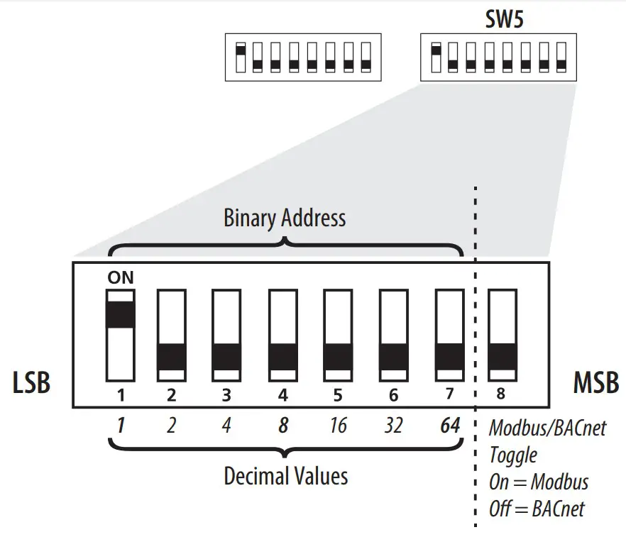 To set an address using the DIP switch, simply add the values of any switches that are in the ON position. For example, an address of 73 is set as shown in the diagram below.
 Position number 1 has an ON value of 1, position number 4 has an ON value of 8 and position number 7 has an ON value of 64 (1 + 8 + 64 = 73).
Communications Configuration
See the Installation section, Step 3 for the location of the DIP switches. The following parameters are configurable:
- Parity (Modbus only): None, Odd, None1 (one stop bit), Even
- Baud rate: 9600, 19200, 38400, 57600 (Modbus), 76800 (BACnet)

Example: No Parity, 19200 Baud
| 1 | 2 | 3 | 4 | 5 | 6 | 7 | 8 |
| off | off | on | off | off | off | off | off |
| None | 19200 Baud | Unused | |||||
Modbus Point Map
Function Codes:
| Function Code | Function |
| 03 | Read holding (RW) registers |
| 04 | Read input (RO) registers |
| 06 | Write single register* |
| 16 | Write multiple registers |
| 01 | Read coils |
| 05 | Write single coil |
| 15 | Write multiple coils |
* Not supported.
All of these values correspond to BACnet objects with the same name. See the BACnet Conformance Statement on page 8 for their definitions.
Note that an attempt to write to “read only” holding registers will give an error and the entire write command will not be executed even if writing to read/write locations were also requested. Exception code 2 is given in this case. “Preserved” means the values is maintained through power outages.
32-Bit Input Registers (Read Only):
| Register | Description |
| 1 | Temperature reading in IEEE 32-bit floating point (°C) |
| 3 | Humidity reading in IEEE 32-bit floating point |
| 9-41 | Model (numeric representation of ASCII characters) |
| 42-45 | Serial number (numeric representation of ASCII characters) |
32-Bit Holding Registers (Read/Write):
| Register | Description |
| 7* | Device name (numeric representation of ASCII characters) |
*Preserved during power outages.
Coils (Read/Write):
| Register | Description |
| 5* | Temperature (°C) |
*Preserved during power outages.
BACnet Descriptions
Note: In the tables below, all properties are read-only unless otherwise noted. “Preserved” means the value is maintained through power outages.
Present_Value Range Restrictions:
| Object Name | Minimum Value | Maximum Value |
| DEV – Object_Name | 1 Character | 65 Characters |
| Device_Instance | 0 | 4,194,302 |
Standard Object Types Supported:
| Object Type | Supported Optional Properties | Writable Properties |
| Analog Input – AI | Reliability | None |
| Binary Value – BV | None | Present Value |
| Device – DEV | Max Info Frames Max_Master | APDU_Timeout Max_Master Object_Name |
Objects Table:
| Object Name | Object Identifier | Object Property |
| Room Temperature | AI 1 | Temperature in Room (°C) |
| Room Humidity | AI 2 | Humidity in Room |
| Temperature Units* | BV4 | ACTIVE displays temperature in Fahrenhiet INACTIVE displays temperature in Celsius |
* Preserved during power outages. Applicable to LCD models only.
Device Objects Table:
| Object Name | Object Identifier | Object Property | Description |
| Plant Room Units XXXXXXXX | Vendor_ID + nnn | Object _Identifer (R/W) | Unique value where nnn initially is the MS/TP address |
BACnet Protocol Implementation Conformance Statement
Vendor Name: Veris Industries
Product Name: Plant Room Humidity and Temperature Unit
Product Model: HD2XPXXXX
BACnet Protocol Version: 1
BACnet Protocol Revision: 16
Product Description: Environmental Sensor
BACnet Standardized Device Profile (AnnexL): BACnet Application Specific Controller (B-ASC)
LCD Operation
The screen displays sensor values for RH, temperature and Celsius/Fahrenheit.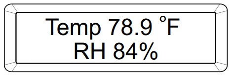
Maximum Power Consumption
| Series | LCD | Temp/RH | Max. Power |
|
HD2 Protocol |
Yes | Yes | 1.5VA @24VAC |
| No | Yes | 0.8VA @24VAC |
China RoHS Compliance Information
Environment-Friendly Use Period (EFUP) Tableb
| – Hazardous Substances | ||||||
| Part Name | (Pb) | ➴ (Hg) | (Cd) | (Cr (VI)) | (PBB) | (PBDE) |
| Electronic | X | O | O | O | O | O |
This table is made according to SJ/T 11364.
O: indicates that the concentration of hazardous substance in all of the homogeneous materials for this part is below the limit as stipulated in GB/T 26572.
X: indicates that concentration of hazardous substance in at least one of the homogeneous materials used for this part is above the limit as stipulated in GB/T 26572
![]() GEX55253-00
GEX55253-00
Page 8 of 8
©2023 Veris Industries USA 800.354.8556 or +1.503.598.4564 / support@veris.com
Alta Labs, Enercept, Enspector, Hawkeye, Trustat, Aerospond, Veris, and the Veris ‘V’
logo are trademarks or registered trademarks of Veris Industries, L.L.C. in the USA and/or other countries.
Other companies’ trademarks are hereby acknowledged to belong to their respective owners.
Documents / Resources
 |
VERIS HD2 Protocol Series Duct Mount Humidity Sensors [pdf] Installation Guide HD2P2AL, HD2P2AX, HD2P2AP, HD2 Protocol Series, HD2 Protocol Series Duct Mount Humidity Sensors, Duct Mount Humidity Sensors, Mount Humidity Sensors, Humidity Sensors, Sensors |