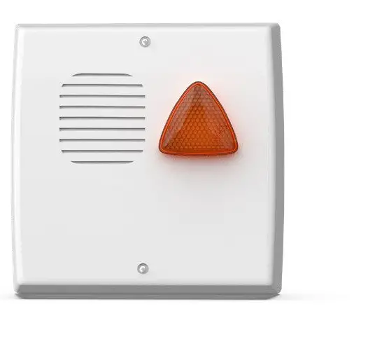
VENITEM L 13.8 Vdc Self-Powered Sounder with Triangular LED Flashing Unit
Product Information
Specifications
- Model: Triade
- Power Supply: 13.8 Vcc
- Features: LED indicator, dip switches, tamper protection
Product Usage Instructions
Mounting Instructions
- Secure the siren to the wall, ensuring the tamper function works correctly.
- Insert the connection cables through the holes at the bottom of the container.
- If necessary, adjust the factory settings by setting the DIP switches as required.
Safety Instructions
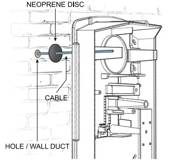
To prevent condensation in the siren, ensure no airflow in the channel. Pass the cable through the closed-cell neoprene disc (provided in the screw kit) between the wall and the bottom of the siren to prevent warm, humid air from entering and causing condensation.
Connection Instructions
Follow the wiring diagram and connect the power supply and control signals to the respective terminals as indicated in the manual based on your setup (3-wire or 2-wire connection).
DESCRIPTION
MOD. TRIADE L – TRIADE QL: self-powered 12 Vdc sounder with high-brightness low-consumption LED flashing unit – double reed tamper against sounder opening and against any attempts of removing the sounder from the wall – programmable sounds and timings – alarm counting – optical and acoustic signaling of System ON/OFF (arming/disarming) -electronic circuit protected against polarity inversion and tropicalized by resin immersion –microprocessor self-check of recharge, battery and speaker – flash reset input – internal cover made of 10/10 zinc-plated steel (Aluzinc system) – outside cover made of painted ABS.
MOD. TRIADE LS – TRIADE QLS: technical features as per MOD. TRIADE L – TRIADE QL with patented double micro anti-foam anti-shock device against hard hits (patent no. 00238576).
MOUNTING
- Screw the sounder on the wall and check if the tamper works properly;
- Insert the connection cables through the holes localed on the sounder base;
- If necessary, modify the default settings acting on the DIPSWITCHES as indicated in the charts here above;
- Connect the battery and the power supply to the control panel;
- Close both internal and external covers using the screws provided;
- Battery must have UL94-HB flammability rate;
- Power supply must be of SELV type.
IMPORTANT
To prevent condensation formation in the sounder, it is important to avoid any air flow inside the duct. To such purpose, run the cable in the closed cell neoprene disc (provided in the screw kit), by placing it between wall and sounder base. This operation prevents condensation from forming inside the sounder; condensation mostly appears in winter and it is usually caused by warm and humid air coming out of the wall where the sounder is installed and passing through the hole located on the sounder base.

CONNECTION SCHEME
| TERMINAL | CONNECTION | |
| 1 | -RIC | Negative power supply 0 Vdc GND |
| 2 | +RIC | Positive power supply +13.8 Vdc |
| 3 | +C | Sounder control (Chart 3) |
| 4 | BSL | Input for sound block |
| 5 | STI | Alarm system ON/OFF notice |
| 6 | RES | Flash reset (when set) |
| 7 | OUT ANM | Anomaly output. Open-collector at 0 Vdc = no anomaly |
| 8 | TAMPER | Auto-protection N.C. |
| 9 | TAMPER | |
A. CONNECTION USING THREE WIRES
Connect 13.8 Vdc power supply coming from the control panel to the corresponding terminals: -RIC negative; +RIC positive; +C positive-missing trigger.
NOTE: DIP-SWITCH NO. 2 IS SET BY THE MANUFACTURER IN OFF POSITION, POSITIVE-MISSING TRIGGER.

CONNECTION USING TWO WIRES
Connect 13.8 Vdc power supply coming from the control panel to the corresponding terminals: -RIC negative; +RIC positive. (make a jumper between +C and +RIC).
NOTE: DIP-SWITCH NO.2 IS SET BY THE MANUFACTURER IN OFF POSITION, POSITIVE-MISSING TRIGGER

BLS TERMINAL, NEGATIVE INPUT FOR SOUND BLOCK
It activates the sound interruption trigger by taking a negative (0 Vdc) to terminal no. 4.
D. STI TERMINAL, SYSTEM STATUS NOTICE (PERMANENT/MOMENTARY ALARM SYSTEM ON/OFF)
DIP 3 in OFF position
- • Giving a positive (13.8 Vdc) to terminal no. 5, all LEDs of the flashing unit flash 3 times (ON). Anomalies are reset to zero.
• Taking away the positive, all LEDs stay lighted up steady for 5 seconds (OFF) and the complete sounder test is launched. In case of anomalies, they are duly notified.
• Pont 1 (R74) CUT: Momentary ON-OFF signaling
• Pont 1 (R74) UNTOUCHED (default setting): Momentary ON-OFF signaling and 1 LED keeps on flashing in intermittent mode until there is positive signal to terminal no. 5.
DIP3 in ON position
- • Giving a negative (0 Vdc) to terminal no. 5, all LEDs of the flashing unit flash 3 times (ON). Anomalies are reset to zero.
• Taking away the negative, all LEDs stay lighted up steady for 5 seconds (OFF) and the complete sounder test is launched. In case of anomalies, they are duly notified.
Activated sounds: To activate sounds (three BEEPs while arming and a long BEEP while disarming) set DIP 4 in ON position.
RES TERMINAL, NEGATIVE INPUT OF FLASHING UNIT RESET
When set (through PONT no. 2), it stops the flashing activity of the flashing unit by taking terminal no. 6 to 0 Vdc for one second.
OUT ANM TERMINAL AND ANOMALY LED
The sounder is managed by a microcontroller able to check if the battery recharging process is going on properly, if the battery status is good, if the speaker is good or faulty and if the power amps are in good condition. In case of anomaly, the open-collector terminal OUT ANM opens and the LD1 LED on the sounder board shows the fault type by making a certain number of flashes followed by a short pause.
The microprocessor automatically performs the battery current test every 4 hours. Moreover, it continuously performs other tests. If the sounder is correctly supplied, the anomaly output (terminal no. 7) usually stays at 0 Vdc (max consumption 50 mA). If any of the tests performed fails, the anomaly output disconnects from the ground and becomes free.
When the sounder receives a power supply for the first time (13.8 Vdc or battery), to make installation easier, anomalies are automatically reset to zero when their cause disappears. After the first alarm trigger, anomalies are reset to zero only through +C, RES, or a command to STI.
To launch the remote test, take terminal no. 5 (STI) to 13.8 Vdc for 10 seconds, then take away the voltage from the terminal. These steps launch the test which will last 60 seconds. During the test, the sounder verifies its own functioning and notifies any anomalies both through the anomaly output (OUT ANM) and the anomaly LED, as indicated in the chart below.
To reset the anomaly to zero, remove its cause first, then wait 10 seconds and take terminal no. 5 (STI) to 13.8 Vdc for at least 10 seconds. When the command is taken away from terminal +C for a very short time lapse, all anomalies are reset to zero except those concerning the battery. After 4 hours from battery restore, the sounder performs the tests once again and updates the anomaly notices, including battery anomaly.
In case any anomaly appears, the flashing unit LEDs flash faster and the acoustic notice at arming becomes a single BEEP.
| ANOMALY NOTICE CHART
LD1 ANOMALY RED LED ANOMALY OUTPUT (OUT NO. 7) |
||
| Speaker interruption
(test performed every 10 s) |
1 flash | Output open (Open collector off) |
| No recharge current (recharge current is lower than 11.5 Vdc) (test performed every 10 s) |
2 flashes |
Output open (Open collector off) |
| Battery is disconnected, is lower than
2.5 Vdc (test performed every 12 hours) |
3 flashes | Output open (Open collector off) |
| Battery is insufficient, is lower than 10 Vdc (test performed every 12 hours) | 4 flashes | Output open (Open collector off) |
| Internal battery resistor > 3.5 ohm (test performed every 12 hours) | 5 flashes | Output open (Open collector off) |
| Speaker power amps are interrupted (test performed every 10 seconds) | 6 flashes | Output open (Open collector off) |
| Sounder is not powered or sounder microprocesso is faulty | Off | Output open (Open collector off) |
| No anomalies | Off | Output to ground, 0 Vdc (Open collector attivo) |
ANTI-OPENING AND ANTI-REMOVAL TAMPER CONNECTION
Connect TAMPER terminals no. 8 and no. 9 to the tamper line coming from the control panel.
BATTERY CONNECTION
Connect the 12 Vdc battery to the corresponding connector faston.
PROGRAMMAZIONE
DIP SWITCHES SETTING
DIP switches can be moved only within the first 12 hours after the board is powered. After this period, DIP switch settings will be stored and any further switching will be useless. By disconnecting battery and power supply, DIP switches will return to active for another 12 hours.
CHART 1 – DIPSWITCHES AND JUMPERS
| DIP/PONT | FUNCTION |
| DIP 1 | Alarm timing |
| DIP 2 | Alarm input polarity |
| DIP 3 | Alarm system ON/OFF notice |
| DIP 4 | Tone selection |
| PONT.1 | Alarm system status notice |
| PONT.2 | Flashing unit control |
| PONT.3 | Maximum daily alarms |
CHART 2 – ALARM TIMING
| DIP 1 | ALARM TIMING |
| OFF
(default setting) |
3 minutes |
| ON | 8 minutes |
CHART 3 – ALARM INPUT POLARITY OF SOUNDER COMMAND, TERMINAL NO. 3
| DIP 2 | TERMINAL 3 |
| OFF
(default setting) |
Positive-missing (alarm if disconnected or 0 Vdc) |
| ON | Negative-missing (alarm if disconnected or +12 Vdc) |
CHART 4 – ALARM SYSTEM ON/OFF NOTICE, TERMINAL NO. 5
| DIP 3 | NOTICE (SOUND) |
| OFF
(default setting) |
STI is open = alarm system is disarmed (OFF),
STI 12 Vdc = alarm system is armed (ON). Flashes as per PONT 1 |
| ON | STI is open = alarm system is disarmed (OFF),
STI 0 Vdc = alarm system is armed (ON). Flashes as per PONT 1 |
CHART 5 – TONE SELECTION
| DIP 4 | TONE | FREQUENCY LIMITS (Hz) |
| OFF
(default setting) CERTIFIED |
Increasing-Continuous-Decreasing-Continuous |
1,400 ÷ 1,800 |
|
ON |
Increasing-Decreasing (NFC 48-265) | 1,400 ÷ 1,600 |
| SOUND IS ACTIVATED ON STI TERMINAL
(3 BEEPs while arming and a long BEEP while disarming) |
||
CHART 6 – ALARM SYSTEM STATUS (ARMED/DISARMED) NOTICE
| PONT. 1 (R74) | TERMINAL 5 | FLASH STATUS (ON/OFF) |
| CONNECTED
(default setting) |
+12 Vdc | All LEDs flash 3 times and a LED keeps on flashing |
| Disconnected or 0 Vdc | All LEDs flash 3 times and a LED keeps on flashing | |
|
TAGLIATO |
+12 Vdc | All LEDs flash 3 times |
| Disconnected or 0 Vdc | All LEDs stay lighted up for 4 seconds and then switch off |
CHART 7 – FLASHING UNIT CONTROL
| PONT. 2 (R75) | FLASHING UNIT BEHAVIOUR |
| CONNECTED
(default setting) |
The flash starts through the sounder trigger (+C) and stops with the sounder trigger (+C) |
| CUT | The flash starts through the sounder trigger (+C) and stops through the flash reset (RES) |
CHART 8 – DAILY ALARMS COUNTING
| PONT. 3 (R85) | ALARMS NUMBER DURING THE 24 HOURS AFTER THE FIRST ALARM |
| CONNECTED
(default setting) |
Infinite alarms |
|
CUT |
MAX 4 DAILY ALARMS (each alarm is counted only if it lasts at least 30 seconds). IN CASE MORE THAN 4 DAILY ALARMS OCCUR, THE SOUNDER
FLASHES WITH NO SOUND (STI resets alarm counting) |
INSTALLATION/MAINTENANCE ADVICES
In case the sounder does not work properly, verify if the LED located on the main board is flashing. If it flashes, check the ANOMALY NOTICE CHART above.
| TRIADE DIP4 OFF POSITION | ||
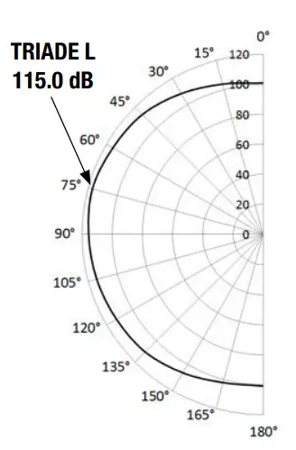
| Angle | TRIADE L | TRIADE LS |
| dB (A) @ 1 m | dB (A) @ 1 m | |
| 15° | 108.3 | 106.8 |
| 45° | 109.8 | 109.7 |
| 75° | 115.0 | 113.1 |
| 105° | 112.2 | 111.8 |
| 135° | 107.6 | 107.8 |
| 165° | 104.7 | 104.2 |
WARRANTY
All Venitem products are granted against factory or material defects. In order to improve design and quality of the products, Venitem reserves the right to modify them without prior notice. All faulty or defective items must be returned to the supplier.
TECHNICAL FEATURES
|
Voltage |
Rate power supply voltage | 13.8 Vdc |
| Minimum – maximum command limits | 4 Vdc – 5.4 Vdc;
10.8 Vdc – 11.9 Vdc; 0.51 Vdc – 1.55 Vdc |
|
| Minimum power supply | 10.5 Vdc | |
| Maximum power supply | 15.5 Vdc | |
|
Current |
Sound consumption from
battery |
1.3 A +100/-300 mA |
| Maximum recharge | 700 mA ± 100 mA | |
| Flashing unit consumption | 80 mA ± 10 mA | |
| Consumption in stand-by | 15 mA | |
| Consumption from control
inputs |
+0.5 mA @ 12 Vdc;
-0.3 mA @ 0 Vdc |
|
| Open collector | -10 mA Max | |
| Fundamental frequency | All models (DIP 4 in OFF position, CERTIFIED TONE) – 1435 Hz | |
| Sound pressure | See diagram 1 | |
| LED flashing unit life | 1,000,000 flashes | |
| Timing | 3 minutes, settable at 8 minutes | |
| Battery capacity | 12 Vdc 2.0 Ah | |
| Switch tamper
range |
N.C. – 0.2 A max. | |
| MECHANICS | ||
| External cover | TRIADE L – TRIADE LS TRIADE QL – TRIADE QLS | Painted ABS |
| Internal cover | Zinc-plated steel | |
| Flashing unit lens | Polycarbonate | |
| Protection degree | IP 44 | |
| Environmental
class |
IV (all’esterno) | |
| Security degree | Degree 3 | |
| Working temperature
conditions |
Da –25 °C a +55 °C |
|
| Size | TRIADE | 206 x 206 x 97 mm (H x L x D) |
| Weight | TRIADE | 2,594 g |
| Standards compliance | T031:2017 + A1:2018 | |
| Certifying Body
(IMQ-SISTEMI DI SICUREZZA) |
EN50131-4:2019 | |
Headquarters
Via del Lavoro, 10 30030 Salzano (VE) – Italy
Tel. +39.041.5740374 – Fax +39.041.5740388
info@venitem.com – www.venitem.com
FAQ
Q: How do I troubleshoot if the red LED indicator shows an anomaly?
A: Refer to the table of signals and anomalies in the manual to identify the specific issue causing the red LED to indicate an anomaly.
Q: What should I do if there is a power supply issue or battery failure?
A: If you encounter power supply issues or battery failures, check the connections, battery voltage levels, and internal resistance as per the manual’s guidelines.
Documents / Resources
 |
VENITEM L 13.8 Vdc Self Powered Sounder with Triangular LED Flashing Unit [pdf] Instruction Manual L 13.8, L 13.8 Vdc Self Powered Sounder with Triangular LED Flashing Unit, Self Powered Sounder with Triangular LED Flashing Unit, Powered Sounder with Triangular LED Flashing Unit, Sounder with Triangular LED Flashing Unit, Triangular LED Flashing Unit, LED Flashing Unit, Flashing Unit, Unit |


