USI WM-CW-26 WiFi Module Instructions

WM-CW-26 Setup Environment

Note: WIFI & BT can work at the same time.
WIFI
- Power supply with 3.6V

P.S. Both LEDs in yellow block should turn on,if not please refer to section8 for troubleshooting.
2. insert micro-USB cable for “USB to SDIO adapter” to PC check SDIO card detected!
Use command: ‘dmesg | grep mmc’, check mmc slot number. (Password = usi)

![]()
3. mmc1 → SDIO card in slot #1
execute the script with the #1 to bring up WIFI function.


5. User mode: Throughput by iperf (v2.0.5)
(a) connect to SSID “Y21” which must be OPEN AP (AP’s DHCP must Enable) and get DHCP IP.
Detail command:
wl join <AP’s SSID>
wl status # check WIFI connection if AP and EUT are connected.
rfkill unblock wifi # unblock all locks.
ifconfig wlan0 up # Enable wlan0 interface.
dhclient wlan0 # Get IP from AP.
(optional)ifconfig wlan0 192.168.x.x # Manual set IP but still need to stay in the AP’s IP range.
ifconfig wlan0 # Check EUT if get IP or not.
ping <AP’s IP>

(b) Run iperf
6. mfg mode
(a) TX: run script “test_tx.sh”, choose what RF setting do you want to verify

(b) RX: run script “test_rx.sh”, choose what RF setting do you want to verify

7. Remove WIFI driver when change another EVB: run the script “./down_wifi.sh”

8. Troubleshooting:
1. Can’t detect the SDIO card
a. Please make sure the USB to SDIO adapter board LED A is lighting.
b. re-power cycle for CYW-26 EVB
c. Press the button (Red block) to reset the USB to SDIO adapter board.

BT
1. Power supply with 3.6V and insert the Mini USB cable.

P.S. LED B (yellow block) will turn off is normal when mini-USB cable is plugged.
2. Check UART to USB slot number,
use command: ls /dev/ttyUSB*
/dev/ttyUSB0 → here is #0

3. execute the script with the #0 to bring up BT function
(A) BT user mode for A2DP
a. Don’t close this terminal.

b. Open another terminal and run cmd “hciconfig -a” to make sure only one BT device with UART interface (Cypress Semiconductor Corp.) is active on your system.
!!!! If there is another BT device on your system, here is hci1 with USB interface.
Please make sure to run cmd “sudo hciconfig hci1 down” to disable it. !!!!
(Password: usi)

c. Use BT setting UI to pair a BT headset.


d. Play music “m_set_106.wav”, and make sure the Sound setting to BT A2DP

(B) BT mfg mode for RF test


Choose what RF setting do you want to verify. For example, “t” for TX test here.
P.S. BT support BR/EDR/BLE 1M, not support BLE coded (125K, 500K).
P.S. BT is class2 (short range, output power less than 10dBm).
Remote Control
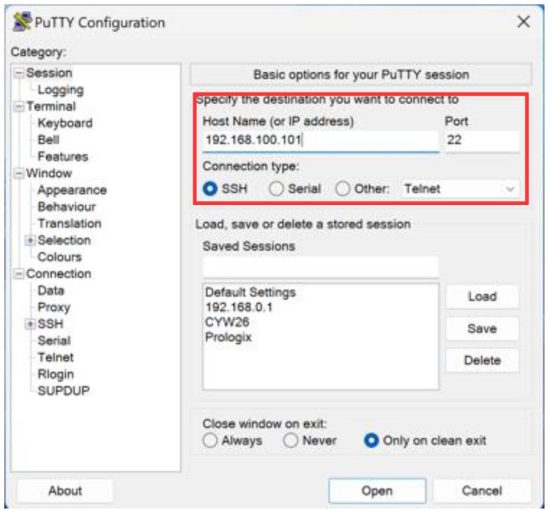
Use Putty to remote control EUT when doing radiated test.
- Setup EUT control PC’s RJ45 LAN to 192.168.100.101 (OS: Ubuntu)
- Setup remote control PC’s (outside chamber) RJ45 LAN to 192.168.100.100
- Putty setup as below,
4. User login: cyw26
Password: usi

Suggestion of module placement on the host PCB


Antenna Information


Regulatory Notices
Federal Communication Commission (FCC) – USA
![]()
This device complies with Part 15 of the FCC Rules. Operation is subject to the following two conditions: (1) This device may not cause harmful interference, and (2) this device must accept any interference received, including interference that may cause undesired operation. This equipment has been tested and found to comply with the limits for a Class B digital device, pursuant to Part 15 of the FCC Rules. These limits are designed to provide reasonable protection against harmful interference in a residential installation. This equipment generates, uses and can radiate radio frequency energy and, if not installed and used in accordance with the instructions, may cause harmful interference to radio communications. However, there is no guarantee that interference will not occur in a particular installation. If this equipment does cause harmful interference to radio or television reception, which can be determined by turning the equipment off and on, the user is encouraged to try to correct the interference by one of the following measures:
- Reorient or relocate the receiving antenna.
- Increase the separation between the equipment and receiver.
- Connect the equipment into an outlet on a circuit different from that
- to which the receiver is connected.
- Consult the dealer or an experienced radio/TV technician for help.
Radiation Exposure Statement:
This equipment complies with FCC radiation exposure limits set forth for an uncontrolled environment. This equipment should be installed and operated with minimum distance 20cm between the radiator & your body.
The final end product must be labeled in a visible area with the following: “Contains FCC ID: COF-WMCW26”. The grantee’s FCC ID can be used only when all FCC compliance requirements are met.
This transmitter module is tested as a subsystem and its certification does not cover the FCC Part 15 Subpart B (unintentional radiator) rule requirement applicable to the final host. The final host will still need to be reassessed for compliance to this portion of rule requirements if applicable.
As long as all conditions above are met, further transmitter test will not be required. However, the OEM integrator is still responsible for testing their end-product for any additional compliance requirements required with this module installed.
IMPORTANT NOTE: If these conditions cannot be met (for example certain laptop configurations or co-location with another transmitter), then the FCC authorization is no longer considered valid, and the FCC ID cannot be used on the final product. In these circumstances, the OEM integrator will be responsible for re- evaluating the end product (including the transmitter) and obtaining a separate FCC authorization.
Based on KDB 996369 D03 OEM Manual v01r01
§2.2 List of applicable FCC rules:
The module, WM-CW-26, complies with the following,
FCC CFR47 Part 15 Subpart C regulations:
§15.203 Antenna Requirement
§15.204 External radio frequency power amplifiers and antenna modifications.
§15.212 Modular Transmitters §15.207 Conducted Limits
§15.247 Operation within the bands 902-928 MHz, 2400-2483.5 MHz, and 5725-5850 MHz (digitallymodulated)
FCC CFR47 Part 15 Subpart A—General
§15.19 Labeling requirements
§15.21 Information to user
§2.3 Operational Use Conditions:
The module, WM-CW-26, has been approved for use in the US, Canada and Japan.
Changes or modifications to the module could void the user’s authority to operate the module.
The host product operating conditions must be such that there is a minimum separation distance of 20 cm between the antenna and nearby persons.
§2.4 Limited Module procedures:
The module, WM-CW-26, has full modular approval.
§2.5 Trace antenna designs:
The module, WM-CW-26, does not require Micro-Strip antennas or traces on the host device. All traces and antennas are contained on the module.
§2.6 RF exposure considerations:
The host product operating conditions must be such that there is a minimum separation distance of 20 cm between the antenna radiating structures and nearby persons. The host manufacturer is obligated to confirm the use conditions of the host product to ensure that the distance specified in the instructions is met.
The following statement must be included as a CAUTION statement in manuals and OEM products to alert end users of FCC RF Exposure compliance:
“To satisfy FCC RF Exposure requirements for mobile and base station transmission devices, a separation distance of 20 cm or more should be maintained between the antenna of this device and persons during operation. To ensure compliance, operation at closer than this distance is not recommended. The antenna(s) used for this transmitter must not be co-located or operating in conjunction with any other antenna or transmitter.”
§2.7 Antennas:
The module, WM-CW-26, uses a non-detachable ceramic chip antenna on the module, thus no antenna other than that furnished by the responsible party shall be used with the device.
§2.8 Label and compliance information:
Host product manufacturer must provide a physical label stating, “Contains FCC ID: COF-WMCW26” and “IC: 10293A-WMCW26” in a visible location on the finished product.
The module host shall bear the following statement in a conspicuous location on the host and in the manual:
“This device complies with part 15 of the FCC Rules. Operation is subject to the following two conditions: (1) This device may not cause harmful interference, and (2) this device must accept any interference received, including interference that may cause undesired operation.
This device contains licence-exempt transmitter(s)/receiver(s) that comply with Innovation, Science and Economic Development Canada’s licence-exempt RSS(s). Operation is subject to the following two conditions: (1) This device may not cause interference. (2) This device must accept any interference, including interference that may cause undesired operation of the device.
§2.9 Information on test modes and additional testing requirements:
Host manufacturer should confirm proper operation using a known good module to link to the installed module. Test procedure for the host will require a particular setting to address the good module and proper operational response will be checked.
§2.10 Additional testing, Part 15 Subpart B disclaimer:
The modular transmitter is only FCC authorized for the specific rule parts (i.e., FCC transmitter rules, i.e., §15.207, §15.247) listed on the grant, and the host product manufacturer is responsible for compliance to any other FCC rules that apply to the host not covered by the modular transmitter grant of certification, such as Part 15 Subpart B, Unintentional Radiators. Compliance should be checked with all transmitters operating.
§2.11 Note EMI Considerations
Host manufacture is recommended to use D04 Module Integration Guide recommending as “best practice” RF design engineering testing and evaluation in case non-linear interactions generate additional non-compliant limits due to module placement to host components or properties For standalone mode, reference the guidance in D04 Module Integration Guide and for simultaneous mode7; see D02 Module Q&A Question 12, which permits the host manufacturer to confirm compliance.
§2.12 How to make changes
Only Grantees are permitted to make permissive changes, need any support please use below information:
https://www.usiglobal.com/en/enquiry-form
Innovation, Science and Economic Development (ISED) – Canada
This device complies with ISED’s license-exempt RSSs. Operation is subject to the following two conditions: this device may not cause interference, and this device must accept any interference, including interference that may cause undesired operation of the device.
CAN ICES-3(B)/ NMB-3(B)
This device and its antenna(s) must not be co-located or operating in conjunction with any other antenna or transmitter, except tested built-in radios. Cet appareil et son antenne ne doivent pas être situés ou fonctionner en conjonction avec une autre antenne ou un autre émetteur, exception faites des radios intégrées qui ont été testées.
The County Code Selection feature is disabled for products marketed in the US/ Canada. La fonction de sélection de l’indicatif du pays est désactivée pour les produits commercialisés aux États- Unis et au Canada.
This radio transmitter (IC: 10293A-WMCW26 / Model: WM-CW-26) has been approved by ISED to operate with the antenna type listed below with maximum permissible gain indicated. Antenna types not included in this list, having a gain greater than the maximum gain indicated for that type, are strictly prohibited for use with this device.
Radiation Exposure Statement:
This equipment complies with IC radiation exposure limits set forth for an uncontrolled environment. This equipment should be installed and operated with minimum distance 20cm between the radiator & your body. Déclaration d’exposition aux radiations: Cet équipement est conforme aux limites d’exposition aux rayonnements IC établies pour un environnement non contrôlé. Cet équipement doit être installé et utilisé avec un minimum de 20cm de distance entre la source de rayonnement et votre corps.
This device is intended only for OEM integrators under the following conditions: (For module device use) 1) The antenna must be installed such that 20cm is maintained between the antenna and users, and 2) The transmitter module may not be co-located with any other transmitter or antenna. As long as 2 conditions above are met, further transmitter test will not be required. However, the OEM integrator is still responsible for testing their end-product for any additional compliance requirements required with this module installed.
IMPORTANT NOTE: If these conditions cannot be met (for example certain laptop configurations or co-location with another transmitter), then the Canada authorization is no longer considered valid, and the IC ID cannot be used on the final product. In these circumstances, the OEM integrator will be responsible for re- evaluating the end product (including the transmitter) and obtaining a separate Canada authorization.
Label and compliance information The final product must be labeled in a visible area with the following:
“Contains IC: 10293A-WMCW26”.
The grantee’s IC ID can be used only when all IC compliance requirements are met.
Read More About This Manual & Download PDF:
Documents / Resources
 |
USI WM-CW-26 WiFi Module [pdf] Instructions WM-CW-26, WM-CW-26 WiFi Module, WiFi Module, Module |