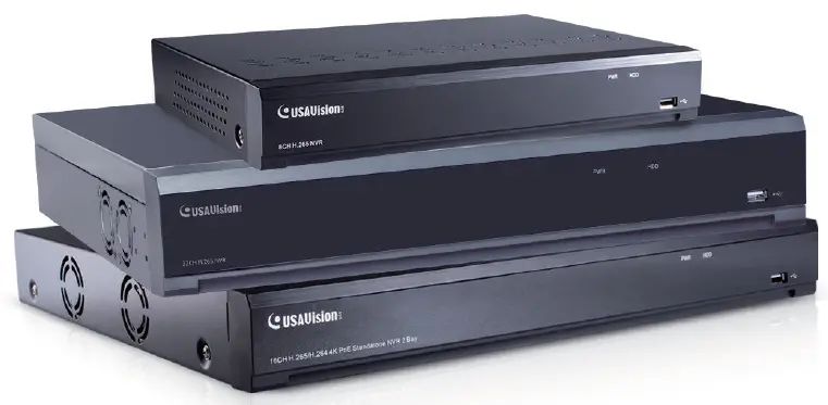
USAVision UA-SNVR3240-N Linux Based Standalone SNVR and Decoder
Product Information
Specifications
- Model: UA-SNVR
- Variants: UA-SNVR3240-N, UA-SNVR1620-P, UA-SNVRL810-P
- Manufacturer: USA Vision Systems Inc.
- Address: 9301 Irvine Blvd, Irvine, CA 92618, USA
- Contact: Tel +1-949-421-5910, Fax +1-949-583-152
- Website: https://www.geovision.com.tw/us/
Product Usage Instructions
Introduction
Before attempting to connect or operate the product, please read the instructions carefully and save the manual for future reference.
Front View
Describe the front view of the product here.
Rear View
Describe the rear view of the product here.
Installation
Follow the steps below for installation:
Connection Diagram
Refer to the provided connection diagram for proper setup.
HDD Installation
Instructions on how to install the HDD in the product.
Power Supply Connection
Guidance on connecting the power supply to the product.
Getting Started
Follow these steps to get started with the product:
Start Wizard
Initiate the Start Wizard to begin setup.
Start Wizard
Detailed instructions on using the Start Wizard.
Connecting IP Cameras
Steps to connect IP cameras to the system.
Getting Started for UA-SNVR3240-N
Specific instructions for starting with UA-SNVR3240-N variant.
Live View Overview
An overview of the live view feature.
Main Window
Description of the main window during live view.
Recording Playback
Guidance on accessing and playing back recordings.
Accessing the Playback Window on UA-SNVR
Steps to access the playback window on UA-SNVR.
Exporting and Playing Recordings
Instructions for exporting and playing recorded footage.
Frequently Asked Questions (FAQ)
- Q: Can I connect wireless cameras to this system?
- A: This system is designed to work with IP cameras, please check compatibility before connecting wireless cameras.
- Q: How do I update the firmware of the UA-SNVR?
- A: Firmware updates can be obtained from our website, follow the provided instructions for updating the firmware.
Quick Start Guide
UA-SNVR
- UA-SNVR3240-N
- UA-SNVR1620-P
- UA-SNVRL810-P
Before attempting to connect or operate this product, please read these instructions carefully and save this manual for future use.
UVSSNVR-QG-A
© 2023 USAVision, Inc. All rights reserved.
Under the copyright laws, this manual may not be copied, in whole or in part, without the written consent of USAVision.
Every effort has been made to ensure that the information in this manual is accurate. USAVision makes no expressed or implied warranty of any kind and assumes no responsibility for errors or omissions. No liability is assumed for incidental or consequential damages arising from the use of the information or products contained herein. Features and specifications are subject to change without notice.
- USA Vision Systems Inc.
- 9301 Irvine Blvd,
- Irvine, CA 92618, USA
- Tel: +1-949-421-5910
- Fax: +1-949-583-152
- https://www.geovision.com.tw/us/
February 2023
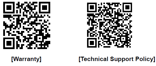
Scan the following QR codes for product warranty and technical support policy
Introduction
Welcome to the UA-SNVR Quick Start Guide. In the following sections, you will learn about the basic installations and configurations. For more details, see UA-SNVR User’s Manual.
Note: The first time you run the NVR, you will be required to set your password immediately in order to protect your privacy. Please be sure to record your username and password and save them in a secure place. If you forget your password, you will be unable to log in the system. For this case, please contact your reseller to reset the password.
Front View
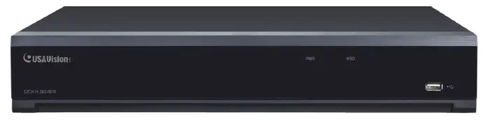
| Item | Description |
| Power LED | Show constant green when power is supplied. |
| HDD LED | Show constant red when the HDD is connected.
Flash red when recording or playback is enabled. |
| USB Port | Connect the supplied mouse or USB flash memory. |
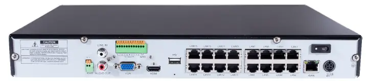
Rear View
UA-SNVR3240-N
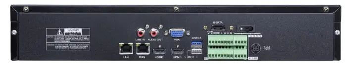
| Item | Description |
| Power Switch | Start up and shut down the NVR system. |
| Power Port | Connect the attached power supply. |
| USB Port | Connect a USB device, such as USB mouse and USB flash disk. |
| Sensor / Alarm / RS-485
Terminal Block |
Connect to sensor, alarming devices, and/or RS-485 PTZ cameras. |
| Reset | Restore the device to its default settings. The reset hole is under the USB Port. |
| HDMI Port | Connect a HDMI-supported monitor. |
| VGA Port | Connect a VGA monitor, such as PC monitor. |
| LINE IN | Connect a microphone. |
| Audio Output | Connect a speaker. |
| WAN Port | Connect to an external network. |
| LAN Port | Connect to a router or switch for connecting cameras. |
IMPORTANT: WAN and LAN ports are not linked, and the LAN port does not have the internet access. If you want to connect IP cameras to the LAN port to create a separate and local network, see 3.2 Getting Started for UA-SNVR3240-N.
UA-SNVR1620-P
| Item | Description |
| Power Switch | Start up and shut down the NVR system. |
| Power Port | Connect the attached power supply. |
| USB Port | Connect a USB device, such as USB mouse and USB flash disk. |
| Sensor / Alarm Terminal Block | Connect to sensor or alarming devices. |
| Reset | Restore the device to its default settings. The reset hole is under the USB Port. |
| HDMI Port | Connect a HDMI-supported monitor. |
| VGA Port | Connect a VGA monitor, such as PC monitor. |
| LINE IN | Connect a microphone. |
| Audio Output | Connect a speaker. |
| WAN Port | Connect to an external network. |
| LAN Port | Connect up to16 cameras, with PoE supply. |
| RS-485 Terminal Block | Connect to a PTZ camera. |
UA-SNVRL810-P

| Item | Description |
| Power Switch | Start up and shut down the NVR system. |
| Power Port | Connect the attached power supply. |
| USB Port | Connect a USB device, such as USB mouse and USB flash disk. |
| Reset | Restore the device to its default settings. The reset hole is under the USB Port. |
| HDMI Port | Connect a HDMI-supported monitor. |
| VGA Port | Connect a VGA monitor, such as PC monitor. |
| Audio Output | Connect a speaker. |
| WAN Port | Connect to an external network. |
| LAN Port | Connect up to 8 cameras, with PoE supply. |
Installation
Connection Diagram
The following diagram is for reference only. The practical connection may be different depending on the NVR you purchased.

- You can connect to other IP cameras remotely over the Internet.
- Connect a CAT.5E or higher RJ45 Ethernet cable for local connectivity. You can connect to other IP cameras through your local network.
- Two-way voice conversation with the remote PC.
- Connect an external hard disk drive to back up files stored on the NVR.
- Connect the included power cable.
- Use the USB flash disk for backup, camera, or system upgrade.
- Connect a RS-485 device such as speed dome camera.
- Connect an external alarm output device such as siren.
- Connect external alarm sensors.
- Connect the video output of the NVR to the TV or monitor via HDMI or VGA connection.
- Connect speakers if you want to listen to the live audio or audio playback from the NVR.
- Connect PoE IP cameras. It may take up to 1 minute for the cameras to start transmitting video to the NVR.
Caution: Do not install or remove the hard disk drive while the power is turned on.
- Connect the data and power cables to the two hard disk drives and place the hard disk drives on the NVR case.
- Carefully flip the NVR case and secure the hard disk drives to the NVR with the eight (8) screws

Power Supply Connection
Caution: Only use the supplied power adapter that comes with the NVR.
Connect one end of the power adapter to the power connector on the back of the NVR. Plug the other end of the power adapter into the wall outlet. And press the Power Switch to turn on the power.

Getting Started
Start Wizard
Note: The Start Wizard does not work for UA-SNVR3240-N. For the first-time users of this model, see 3.2 Getting Started for UA-SNVR3240-N.
Start Wizard
Click Start Wizard to proceed to the next step.

Connecting IP Cameras
After finishing setting Network Configuration and Date and Time, this page appears.

Click Search to search for IP cameras in the same network. Select the IP camera(s) you want to add, and then click ![]() icon to add to the NVR.
icon to add to the NVR.
Or, click![]() button to manually add an individual IP camera to a single channel. This dialog box appears.
button to manually add an individual IP camera to a single channel. This dialog box appears.

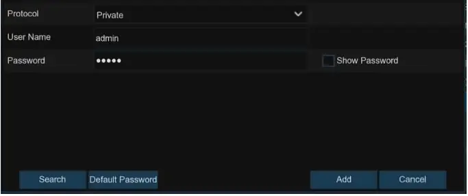
- IP Address/Domain: Enter the IP address or domain name of the IP camera.
- Alias: Name the IP camera.
- Port: It is set to 80 by default. Modify it if necessary.
- Protocol: Select the protocol of the IP camera from the dropdown menu.
- Select Onvif for UA-B20004F / UA-B40004F / UA-B4000VF-S / UA-D20004F /UA-D40002F / UA-D4000VF-S / UA-R40002F-SA / GV-IP cameras
- Select Private for UA-B580F3 / UA-R500F2 / UA-R560F2 / UA-R580F2 /UA-R800F2
- Select RTSP, and type the commands as shown below:
- Main Stream: rtsp://IP address:port/rtsp/streaming?channel=xx&subtype=0
- Sub Stream: rtsp://IP address:port/rtsp/streaming?channel=xx&subtype=1
- User Name: Enter the username of the IP camera.
- Password: Enter the password of the IP camera.
Click Add to add the IP camera to the NVR.
IMPORTANT
- The system fills in the ID and password using admin/admin123. for UA-B580F3 /UA-R500F2 / UA-R560F2 / UA-R580F2 / UA-R800F2 by default. Make sure to enter the correct ID and password of the IP cameras if the login credentials have been changed on the IP cameras before connecting to UA-SNVR models.
- The default password is 123456 for the following IP camera models: UA-B20004F /UA-B40004F / UA-B4000VF-S / UA-D20004F / UA-D40002F / UA-D4000VF-S /UA-R40002F-SA. To modify the password on the camera’s Web interface, refer to Network Cameras User Manual for details.
Getting Started for UA-SNVR3240-N
UA-SNVR3240-N has two network ports, LAN and WAN. Both ports are not linked, and the LAN port does not have the internet access. Therefore, there are two methods for connecting IP cameras to UA-SNVR3240-N.
- Connect IP cameras and UA-SNVR3240-N to the WAN port, using a router.
- Connect IP cameras to the LAN port, using a router, to have a separate and local network.
To connect IP cameras to the LAN port, follow the steps below
- Before connecting, configure the following first:
- Prepare a router with a different IP address in the same network segment as the NVR.
- Set up the ID and Password for each IP camera.
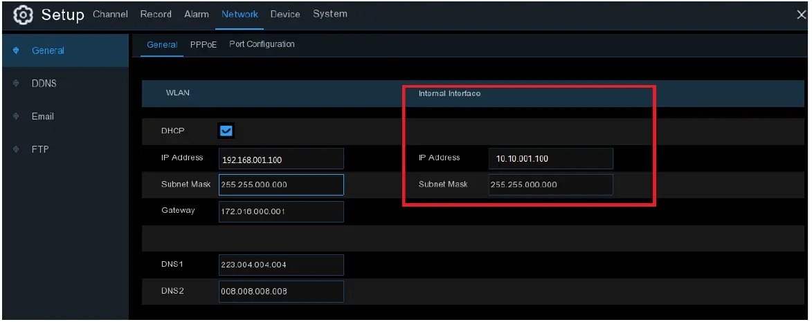
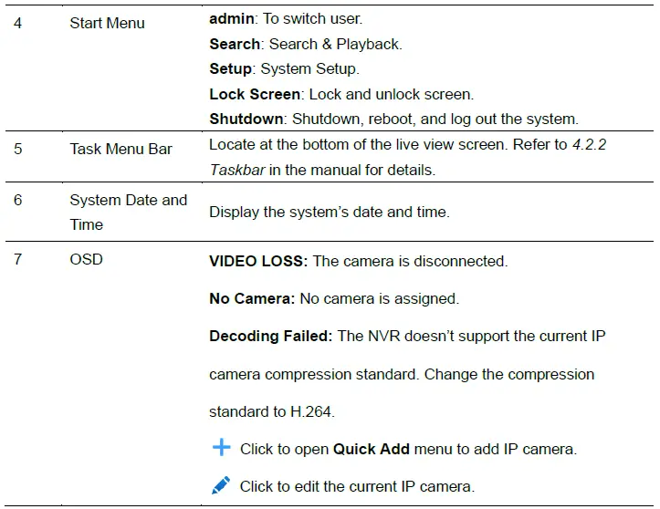
- On the NVR’s taskbar, click Start Menu
 Setup > Network > General.
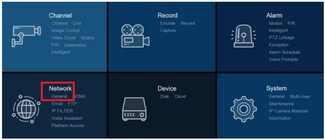
- Under Internal Interface, enter the IP address and Subnet Mask of the router connecting to the NVR. The IP addresses of the WAN and LAN should not be identical, and both should have the same Subnet Mask.
- On the NVR’s taskbar, click Start Menu >Setup > Channel > Channel.
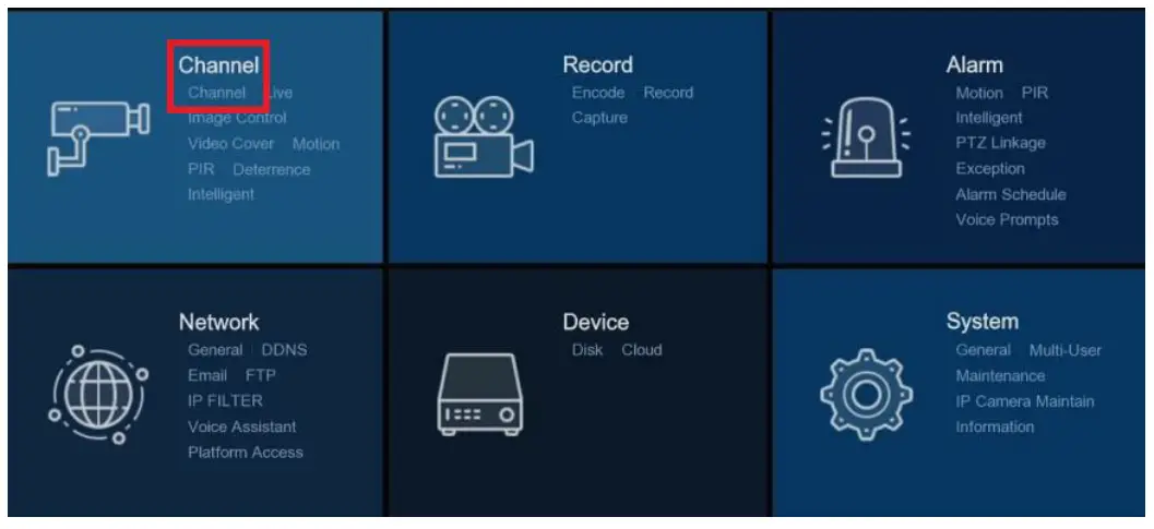
- Click Search to search for IP cameras from local network. The cameras found should be displayed in a list.

- Select desired cameras in the list, and click Add or Add All. The Add IP Camera dialog box appears. The following is the dialog box when you click Add to add a camera.
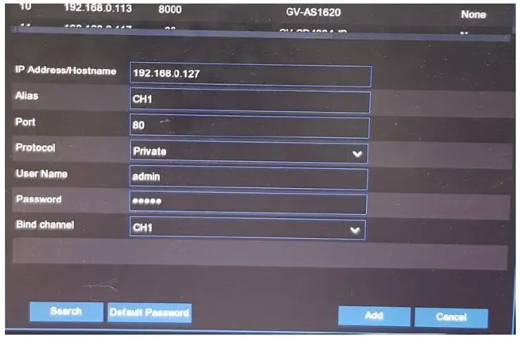
- Port: It is set to 80 by default. Modify it if necessary.
- Protocol: Select the protocol of the IP camera from the dropdown menu.
- Select Onvif for UA-B20004F / UA-B40004F / UA-B4000VF-S / UA-D20004F /UA-D40002F / UA-D4000VF-S / UA-R40002F-SA / GV-IP cameras
- Select Private for UA-B580F3 / UA-R500F2 / UA-R560F2 / UA-R580F2 /UA-R800F2
- Select RTSP, and type the commands as the example below
Main Stream: rtsp://IP address:port/rtsp/streaming?channel=xx&subtype=0
Sub Stream: rtsp://IP address:port/rtsp/streaming?channel=xx&subtype=1
- User Name: Enter the username of the IP camera.
- Password: Enter the password of the IP camera.
- Bind channel: Select a channel of the NVR you want to attach to.
IMPORTANT
- The system fills in the ID and password using admin/admin123. for UA-B580F3 / UA-R500F2 / UA-R560F2 / UA-R580F2 / UA-R800F2 by default. Make sure to enter the correct ID and password of the IP cameras when adding them to the NVR.
- The default password is 123456 for the following IP camera models: UA-B20004F / UA-B40004F / UA-B4000VF-S / UA-D20004F / UA-D40002F / UA-D4000VF-S / UA-R40002F-SA. To modify the password on the camera’s Web interface, refer to Network Cameras User Manual for details.
Live View Overview
Main Window


For details, see 4.2 Live View Screen Overview in the Manual.
Recording Playback
Accessing the Playback Window on UA-SNVR
On the main window, click the Playback icon on the toolbar at the bottom to play back the video. At the lower left corner of the main window, you can also click the Start icon
 and Search to open the playback window to customize the playback channels and event types, and then play back the video.
For details, see Chapter 6 Search, Playback & Backup in the User’s Manual.
Exporting and Playing Recordings
Saving Video Clips from Local UA-SNVR
- At the lower left corner of the main window, click the Start icon and Search to open the playback window.
- Insert a USB flash drive, and click the Save icon
 from the video playback controls to save the video clips.
Exporting Video Clips from the Web interface of UA-SNVR
- On the main page, click the Playback tab to open the playback page.
- After searching for the desired recordings, click the Download icon
 from the video playback controls.
 - Select the desired files and click Start Download to download the video clips.
Playing Video Clips Exported Locally or from the Web Interface of UA-SNVR
- Install one of the following players:
- USAVision Player
- VLC Media Player
- KM Player
- Launch the player and locate the recordings, and wait for 3 ~ 30 seconds before it starts to play.
Note: Make sure to launch and player first and locate the recordings on the player to prevent latency.
Remote Access via Web Client
Use the Web Client to remotely access your NVR at any time via a PC. Before you access the Web Client, ensure that your PC’s system meets the basic requirements and that the network settings of the NVR are configured properly.
Basic System Requirements
| Item | Minimum | Recommended |
| CPU | Intel Core™ i5 CPU | Intel Core™ i5 CPU or higher |
| RAM | 4G or more | 8G or more |
| Hard Drive | 500G or more | 1000G or more |
| Display RAM | 2G or more | 4G or more |
| Display Resolution | 1280*1024 | 1920*1080 |
| OS | Windows 7 or above
Mac OS X 10.9 or above |
|
| DirectX | DirectX 11 | |
| Direct3D | Acceleration Function | |
| Ethernet Adapter | 10/100/1000M Ethernet Adapter | |
|
Browser |
|
|
Looking Up the Dynamic IP Address
By default, when the NVR is connected LAN with DHCP server, it is automatically assigned with a dynamic IP address. Follow the steps below to look up its IP address.
- Download and install UVS Device Utility from our website.
- On the UVS Device Utility window, click Search to search for the devices connected in the same LAN.
- Find the device with its Mac Address and click on its IP address.

- The login web page appears.

Upgrading Firmware
You can upgrade the firmware on the device remotely through UVS Device Utility. Follow the instructions below.
Upgrading Firmware
- Download and install UVS Device Utility from our website.
- On the UVS Device Utility window, click Upgrade and select the device you wish to upgrade the firmware on. Optionally, select several devices to upgrade the firmware at once.

- Click Open to locate the firmware file saved at your local computer.
- Enter the username and password of the device.
- Click Upgrade to process the upgrade.
Documents / Resources
 |
USAVision UA-SNVR3240-N Linux Based Standalone SNVR and Decoder [pdf] User Guide UA-SNVR3240-N, UA-SNVR1620-P, UA-SNVRL810-P, UA-SNVR3240-N Linux Based Standalone SNVR and Decoder, UA-SNVR3240-N, Linux Based Standalone SNVR and Decoder, Based Standalone SNVR and Decoder, Standalone SNVR and Decoder, Decoder |


