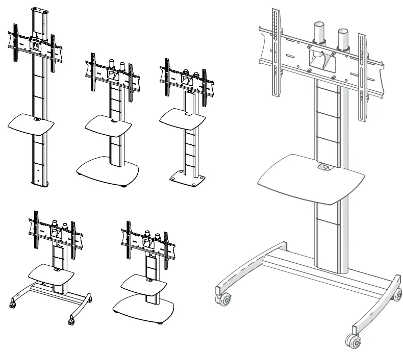
UNICOL AVLT Avecta Low Level

Specifications:
- Product Models: AVHT / AVHP / AVLT / AVLP / AVHB / AVHW
- Screen Size: 33 – 70 inches
- Max. Weight Capacity: 60-70kg
Components:
- 1500mm (High) or 950mm (Low) Columns
- AVP1 500x400mm Shelf
- Twin Column Mount Adapter
- 7.5cm Castors (2 standard, 2 braked)
- Universal Mount Back Plate
- Universal Mount Arms
- Avecta Trolley Base
- 30cm Mast Front In-Fill Panel
- 30cm Mast Rear In-Fill Panel
- 15cm Mast Front In-Fill Panel
- 15cm Mast Rear In-Fill Panel
- Alternative Bases
- Alternative Accessories
Tools Required:
- 4mm & 5mm Allen Keys
- Pozi Head Screwdriver
- 19mm Spanner
- 17mm Spanner
Product Usage Instructions
Step 1: Install Castors
Turn the base upside down and push each castor until it clicks into place. Ensure front castors have brakes applied.
Step 11 (Optional): Fitting a Shelf
If fitting a shelf, choose the desired height and insert it between the panels as you clip them into position.
- 01865 767676
- sales@unicol.com
- www.unicol.com

AVHT / AVHP / AVLT / AVLP / AVHB / AVHW
- Screen Size: 33 – 70”
- Guide Max. Weight: 60-70kg
- *Please check model specific details before installing*
WARNING
- Please carefully inspect the product before assembling. If you notice any apparent damage, call your carrier claims agent and do not continue the installation until it has been reviewed. Please watch for pinch points.
- Do not put your fingers between moveable parts. Do not tamper with or disassemble any spring loaded parts. Before installing, make sure that the supporting surface will support five times the combined load of the solution and the hardware. Never exceed the maximum load capacity. Please also layout all components to ensure that you have all of the required parts before proceeding (see BOM list on following page).
- Use of this product for anything other than its specified use may result in failure or personal
injury. This product is intended for indoor use only. - We recommend using a qualified trades person for installation. Use an assistant or lifting equipment to lift and position products.
- For support, please call: +44 (0)1865 767676 or email: sales@unicol.com
INSTALLERS REQUIRED
- 1 – 2
COMPONENTS


DESCRIPTION
| #
1500mm (High) or 950mm (Low) Columns Note, columns may also be split, see pg. 7 |
QTY
2 |
| 2 AVP1 500x400mm Shelf | 1 |
| 3 Twin Column Mount Adapter | 1 |
| 4 7.5cm Castors (2 standard, 2 braked) | 4 |
| 5 Universal Mount Back Plate | 1 |
| 6 Universal Mount Arms | 2 |
| 7 Avecta Trolley Base | 1 |
| 8 30cm Mast Front In-Fill Panel | 2 |
| 9 30cm Mast Rear In-Fill Panel | 2 |
| 10 15cm Mast Front In-Fill Panel | 4 |
| 11 15cm Mast Rear In-Fill Panel | 4 |
| 12 Alternative Bases | – |
| 13 Alternative Accessories | – |
INSTALLATION
STEP 1
Turn the base upside down and push each castor until it clicks into place. Please ensure that the castors with brakes are located at the front. Place base on the floor and apply brakes on front wheels by pressing brake lever down.
See last page for other base options.
STEP 2
Place the 2 columns with holes, located approx. 75mm from the bottom, over the crocodile lugs on the base.
If using split columns, please go to page 7.

STEP 3
Ensure that the holes line up with the grub screws at the rear of the crocodile lugs. Leave the grub screws loose for now.
STEP 4
Place the column adapter over the top of the two columns (ensuring the grub screws are on the same side as the rear of the base).

STEP 5
Once placed over columns and at the desired height, tighten the two grub screws to secure into place. Tighten up the base grub screws to secure.
STEP 6
Line the back plate up with the mount adapter, as shown above. Fix 4 screws from behind the mount adapter and into the 4 rivet nuts located on the back plate. Ensure back plate is secure and screws are tightened.

STEP 7
Locate the mounting holes on the back of your screen. Line the two mounting arms up and using the tag locks and manufacturer recommended screws (included in fixing kit), attach the arms to the back of the screen.
STEP 8
Line the screen and arms up with the secured back plate and offer it up at a slight angle – allowing the top of the arms to hook over the lip of the back plate.

STEP 9
Gently lower the screen until the arms are securely hanging on top of the back plate. Once centered, adjust the level of the screen with the two top Screws on the mount arms. Once leveled secure the screen by tightening the bottom two screws.
STEP 10
Identify the front mast in-fill panels (the 4 with cut-outs go to the rear). Start with the panel that has the 4-way power socket attached clip into place. Cable up.

STEP 11 (OPTIONAL)
- If fitting a shelf, choose the height you’d like and insert between the panels as you’re clipping them into position.
- To insert, angle the shelf as you offer it up to the columns. Level out and rest it in position. Unlike the infill panels, the shelf does not clip into place.
STEP 12
Identify remaining mast in-fill panels. Start from the bottom and clip 2 of the 3 larger rear panels in, threading cabling through where necessary.

BOLT DOWN
STEP 1A
- Position floor plate and mark through the screw holes (arrows above) where it will be positioned.
- Before you screw through, ensure any cables that are going underneath the plate are threaded through the column grips (circled above).
STEP 1B
- Loosen the grub screws on the jaws of the column grips so that you can slide the columns over. When sliding over, ensuring that any cables are not caught.
- Leave loose for now – follow on with Step 4.

FLOOR-TO-WALL

STEP 1B
- Position floor plate and mark through the screw holes (arrows above) where it will be positioned against a wall and fix in place.
- Loosen the grub screws on the jaws of the column grips so that you can slide the columns over (circled above).
STEP 2B
- Before fixing the top plate into position, slide the twin column mount adapter over the columns. This can be height adjusted throughout the installation.
- Loosen the grub screws on the column grips on the top wall plate and place into columns. Mark through the screw holes and fix into place against a wall. Follow on from Step 6.
SPLIT COLUMNS

STEP 2
All columns have a half-moon notch at one end and 2 of the columns will have holes at 75mm from one end (these will typically be the longer pair of columns). Place the 2 columns with holes over the crocodile lugs on the base.
STEP 3
Ensure that the holes line up with the grub screws at the rear of the crocodile lugs. Leave the grub screws loose for now.

STEP 4
- Place column couplers into columns so that the open jaws are at the top and the grub screws align with the half-moon notch at the rear.
- Ensure grub screws are screwed out enough to hold the column coupler in place.
STEP 5
Place top columns over the column couplers and gently tighten the grub screws to secure. CONTINUE WITH STEP 4 ON PAGE 3.

Any Questions?
- +44 (0)1865 767676
- sales@unicol.com
- unicol.com/instructions
FAQS
Q: How do I choose the correct height for the columns?
A: The columns are available in 1500mm (High) or 950mm (Low) options. Choose based on your preferred screen height.
Q: Can I use alternative bases with this product?
A: Yes, alternative bases are available. Refer to the user manual for instructions on using alternative bases.
Q: What should I do if I encounter issues during installation?
A: For installation support, please contact our customer support team at +44 (0)1865 767676 or email us at sales@unicol.com.
Documents / Resources
 |
UNICOL AVLT Avecta Low Level [pdf] Installation Guide AVHT, AVHP, AVLT, AVLP, AVHB, AVHW, AVLT Avecta Low Level, AVLT, Avecta Low Level, Low Level |