Undalogic miniSMU MS01 Compact, High Precision 2 Channel Source Measure Unit
Introduction
About the miniSMU MS01
The miniSMU MS01 is a compact, high-precision 2-channel source-measure unit (SMU) designed for versatile electronic testing and characterisation. Engineered for researchers, engineers, and electronics enthusiasts, the MS01 combines powerful functionality with portability, making it an ideal tool for both laboratory and field use.
Key Features and Benefits
- Dual-Channel Operation: Two independently controllable SMU channels allow for simultaneous testing of multiple components or comparative analysis.
- Full 4-Quadrant Functionality: Capable of both sourcing and sinking voltage or current, providing flexibility for a wide range of testing scenarios.
- High Precision:
- Voltage range: -12V to +12V with 1mV accuracy
- Current range: -180mA to +180mA with accuracy down to 10nA across 5 sub-ranges
- Compact Design: With dimensions of just 137x82x29mm, the MS01 is easily portable and spaceefficient in any workspace.
- Flexible Power Options: Operate via USB-C for currents up to 50mA or use the included 12V DC adapter for full current range.
- Versatile Connectivity: Connect via USB or WiFi 4 for easy integration into your testing setup.
- Intuitive Software Interface: The companion “miniSMU” software enables advanced measurements including I-V curves, stability tests, and maximum power point tracking.
Intended Use and Applications
The miniSMU MS01 is primarily designed for:
- Solar Cell Characterisation: Ideal for university and R&D laboratories working on photovoltaic research and development.
- Semiconductor Testing: Characterise transistors, diodes, and other electronic components with high precision.
- Device Analysis: Perform detailed I-V curve measurements and stability tests on various electronic devices.
- Power Management Studies: Conduct maximum power point tracking for solar cells and other power management applications.
- General Electronic Research: Suitable for a wide range of electronic testing and measurement tasks in academic and industrial settings.
Whether you’re a researcher pushing the boundaries of solar technology, an engineer refining electronic designs, or a student learning the intricacies of electronic characterisation, the miniSMU MS01 provides the tools you need for accurate, reliable, and insightful measurements.
Safety Information
Your safety is our top priority. While the miniSMU MS01 is designed for low-voltage operations, it’s essential to follow proper safety procedures when using any electronic test equipment. Please read and understand these safety guidelines before operating the device.
General Safety Precautions
- Read All Instructions: Carefully read and understand all safety and operating instructions before using the miniSMU MS01.
- Retain Documentation: Keep this user manual and all safety information for future reference.
- Heed Warnings: Follow all warnings on the device and in the operating instructions.
- Use as Intended: The miniSMU MS01 is designed for electronic testing and measurement. Do not use it for any purpose not specifically described in this manual.
- Proper Environment:
- Operate the device in a clean, dry environment.
- Avoid exposure to extreme temperatures, humidity, or direct sunlight.
- Ensure proper ventilation to prevent overheating.
- Handling and Transportation:
- Handle the device with care to avoid physical damage.
- Use the original packaging or an appropriate protective case when transporting the device.
- Maintenance:
- Do not attempt to service the device yourself unless specifically instructed in this manual.
- Refer all servicing to qualified service personnel.
Electrical Safety Considerations
- Low Voltage Operation: While the miniSMU MS01 operates at low voltages (-12V to +12V), always treat it with the same respect as you would any electrical device.
- Power Supply:
- Use only the provided 12V DC power adapter or a USB-C power supply that meets the device specifications.
- Inspect power cords regularly for damage. Do not use the device if the power cord is frayed or damaged.
- Disconnection: In case of any abnormal operation or if you suspect a malfunction, immediately disconnect the device from its power source and any connected equipment.
- Liquid Exposure: Avoid operating the device near liquids or in high-humidity environments. If liquid is spilled on the device, disconnect it immediately and have it checked by a qualified technician before further use.
- Thunderstorms: For added protection during lightning storms, or when the device is left unattended and unused for long periods, unplug it from the power source.
- Connection to Test Objects:
- Always connect test leads to the miniSMU MS01 before connecting them to the circuit under test.
- Disconnect test leads from the circuit under test before disconnecting them from the miniSMU MS01.
- Do not exceed the maximum input voltages and currents specified for each terminal.
- Static Discharge: Be aware of potential static discharge when handling sensitive electronic components. Use appropriate ESD protection measures when necessary.
Remember, while the miniSMU MS01 is designed for safe operation, it’s crucial to always use caution and common sense when working with any electrical equipment. If you have any doubts or questions about safe operation, please contact our support team before proceeding.
RF Exposure Information
This equipment complies with FCC radiation exposure limits set forth for an uncontrolled environment. This equipment should be installed and operated with minimum distance of 20cm between the radiator and your body.
FCC
FCC Warning
This device complies with part 15 of the FCC Rules.
Operation is subject to the following two conditions:
- This device may not cause harmful interference, and
- this device must accept any interference received, including interference that may cause undesired operation.
Any changes or modifications not expressly approved by the party responsible for compliance could void the user’s authority to operate the equipment.
NOTE: This equipment has been tested and found to comply with the limits for a Class B digital device, pursuant to Part 15 of the FCC Rules. These limits are designed to provide reasonable protection against harmful interference in a residential installation. This equipment generates, uses and can radiate radio frequency energy and, if not installed and used in accordance with the instructions, may cause harmful interference to radio communications. However, there is no guarantee that interference will not occur in a particular installation. If this equipment does cause harmful interference to radio or television reception, which can be determined by turning the equipment off and on, the user is encouraged to try to correct the interference by one or more of the following measures:
- Reorient or relocate the receiving antenna.
- Increase the separation between the equipment and receiver.
- Connect the equipment into an outlet on a circuit different from that to which the receiver is connected.
- Consult the dealer or an experienced radio/TV technician for help.
Product Overview
Package Contents
When you unbox your miniSMU MS01, you should find the following items:
- miniSMU MS01 device
- 12V DC power adapter
- USB-C cable
- WiFi antenna (SMA connector)
- Set of BNC to banana plug adapters (2 pairs)
- User manual
- Calibration certificate
If any of these items are missing or damaged, please contact our customer support immediately.
Device Layout and Controls
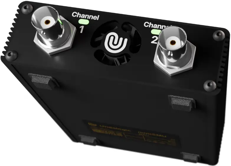
The miniSMU MS01 features a compact and functional design, optimised for computer-controlled operation. Here’s an overview of its layout and controls:
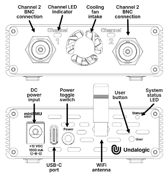
- Front Panel:
- Channel 1 BNC connector
- Channel 2 BNC connector
- Status LED for Channel 1
- Status LED for Channel 2
- Intake for cooling fan
- Rear Panel:
- 12V DC barrel connector (Centre pin positive)
- USB-C port (USB 2.0)
- Power on/off toggle switch
- User button
- SMA antenna connector for WiFi
- Cooling fan exhaust slots
Indicators and Controls
The miniSMU MS01 uses LED indicators to provide immediate feedback on its status, and it’s controlled via computer software.
- Status LEDs (one for each channel):
- Solid green: Channel is active and operating within normal parameters
- Solid red: Channel is in protection mode (current or voltage limit exceeded)
- Off: Channel is inactive
- Power Switch: Located on the rear panel, this toggle switch turns the device on and off.
- WiFi Activation Button: Located on the rear panel, this button activates and deactivates the WiFi radio.
- Computer Control: All other functions and settings of the miniSMU MS01 are controlled via the companion software installed on your computer. The device connects to your computer either through the USB-C port or via WiFi.
Understanding the layout, controls, and indicators of your miniSMU MS01 will help you set up the device correctly and interpret its status accurately. In the next sections, we’ll dive deeper into how to connect the device to your computer and use the software interface for your measurements and experiments.
Technical Specifications
Specifications
- Voltage Specifications
- Range: -12 V to +12 V
- Accuracy: ±(0.1% + 1.5 mV)
- Measurement Resolution: 6 uV
Current Measurement
- Range: -180 mA to +180 mA
- Accuracy: ±(0.2% + 10 nA)
- Resolution: 10 pA
- Current Ranges: Automatically or manually selectable
- 0 to 500 nA
- 500 nA to 20 uA
- 20 uA to 0.5 mA
- 0.5 mA to 13 mA
- 13 mA to 180 mA
Current Sourcing
- Range: -180 mA to +180 mA
- Accuracy: ±(0.2% + 10 nA)
- Resolution: 10 pA
Power Specifications
- Input Power Options:
- 5V via USB-C.
- Note: SMU current limited to 50 mA in USB-powered mode by default.
- 12V via DC barrel connector
- 12V 2000 mA AC-DC power supply included (100-240 V input)
- Maximum Power Draw: 15W
- Output Power: Maximum 2.1 W sourced or sunk per channel
Connectivity
- USB-C (USB 2.0)
- WiFi 4 (802.11b/g/n)
Channel Specifications
- Number of Channels: 2
- Channel Independence: Fully independent operation. Both BNC outer shields are connected together as a common reference point.
- 4-Quadrant Operation: Yes, source and sink capability for both voltage and current
Physical Specifications
- Dimensions: 137mm x 82mm x 29mm (Including WiFi antenna)
- Weight: 225g
Environmental Specifications
- Operating Temperature Range: 0 to 50°C
- Storage Temperature Range: -20 to 70°C
- Humidity Range: 10 to 80% RH
Measurement Capabilities
- I-V curve measurements
- I-V stability measurements (periodic IV curves over long periods)
- Maximum power point tracking (for solar cells)
- Data logging
- Transistor IDS-VDS curves
- Transistor IDS-VGS curves
Software
- Compatible Operating Systems:
- Windows 7 to 11
- Minimum System Requirements:
- Dual-core CPU (1.8GHz or faster)
- 4GB RAM or greater
- 200 MB Drive space
- USB 2.0 connectivity
- Network connectivity (for miniSMU on-network access)
- TCP Port 3333 must be free to access miniSMU over a network.
- Please note: All specifications are subject to change without notice. Always refer to the most recent documentation for the most up-to-date information.
Getting Started
This section will guide you through the process of setting up your miniSMU MS01 for the first time. Please follow these steps carefully to ensure proper operation of your device.
Unpacking and Inspection
- Carefully remove the miniSMU MS01 and all accessories from the packaging.
- Check that all items listed in the “Package Contents” section of this manual are present.
- Inspect the device and accessories for any signs of damage that may have occurred during shipping.
- If any items are missing or damaged, please contact our customer support immediately before proceeding.
Power Supply Options
The miniSMU MS01 can be powered in two ways:
USB-C Power
- Locate the USB-C port on the rear panel of the device.
- Connect the provided USB-C cable to this port.
- Connect the other end of the USB-C cable to a USB port on your computer or a USB power adapter.
Note: USB-C power is suitable for operations requiring up to 100mA per channel. 12V DC Power Adapter
For full current range operation (up to 175mA per channel):
- Locate the 12V DC barrel connector on the rear panel of the device.
- Connect the provided 12V DC power adapter to this port.
- Plug the power adapter into a suitable wall outlet.
Warning: Use only the provided 12V DC power adapter or an equivalent adapter with the correct specifications to avoid damaging your device.
Connectivity Setup
The miniSMU MS01 can be connected to your computer via USB or WiFi.
USB Connection
- Ensure the device is powered on
- Connect the USB-C cable to the USB-C port on the rear of the device.
- Connect the other end to a USB port on your computer.
- Your computer should recognise the device automatically. If prompted, allow your computer to install any necessary drivers.
WiFi Setup
- Ensure the device is powered on and connected to a PC using a USB-C cable.
- In the miniSMU desktop application, connect to the miniSMU’s port
- Click the gear icon in the desktop application connection window and click “Wi-Fi Settings”
- Click “Enable” under Wi-Fi Radio
- Click “Scan Wi-Fi Networks” for available networks, select the appropriate network and enter the network’s password
- Upon successful connection, the ability to automatically connect to this Wi-Fi network upon miniSMU startup can be toggled.
Software Installation
- Obtain a copy of the miniSMU desktop application from Undalogic through an email request.
- Run the installer and follow the on-screen instructions to complete the installation.
Once you’ve completed these steps, your miniSMU MS01 should be ready for use. The next section will guide you through basic operation and how to use the software interface to control your device.
Basic Operation
- This section will guide you through the fundamental operations of your miniSMU MS01, including powering on the device and performing basic measurements.
Powering On and Off
Powering On:
- Ensure the device is connected to a power source (either via USB-C or the 12V DC adapter).
- Locate the power switch on the rear panel of the device.
- Toggle the switch to the ON position.
- The status LEDs on the front panel should illuminate, indicating the device is powered on.
Powering Off:
- Toggle the power switch on the rear panel to the OFF position.
- All LEDs should turn off, indicating the device is powered down.
Connecting to the Device
- Before performing any operations, you need to establish a connection with the miniSMU MS01 either via
- USB or WiFi. Refer to the “Getting Started” section for detailed connection instructions.
Basic Command Structure
- The miniSMU MS01 uses a command-based interface for operation. Commands are sent to the device through the software interface. The general structure of commands is:
- COMMAND [:SUBCOMMAND] [PARAMETER]
- For queries, append a question mark (?) to the command.
- A list of available commands and their functions is listed below.
| Command | Function |
| *IDN? | Returns device identification information |
| *RST | Reboots the device |
| SYST:TIME | Sets the system time |
| SYST:WIFI DIS | Disables WiFi |
| SYST:WIFI ENA | Enables WiFi |
| SYST:WIFI:AUTO? | Queries WiFi autoconnect state |
| SYST:WIFI:AUTO DIS | Disables WiFi autoconnect |
| SYST:WIFI:AUTO ENA | Enables WiFi autoconnect |
| SYST:WIFI:SCAN? | Scans for available WiFi networks |
| SYST:WIFI? | Queries current WiFi status |
| SYST:WIFI:SSID “” | Sets WiFi SSID |
| SYST:WIFI:PASS “” | Sets WiFi password |
| SYST:WIFI:SSID? | Queries current WiFi SSID |
| SYST:TEMP? | Queries system temperatures |
| SOURx:CURR:PROT yy | Sets current protection limit (yy A) for channel x |
| Command | Function |
| SOURx:CURR yy | Sets current source (yy A) output for channel x |
| SOURx:VOLT:PROT yy | Sets voltage protection limit (yy V) for channel x |
| SOURx:VOLT yy | Sets voltage source output (yy V) for channel x |
| SOURx:FIMV ENA | Enables FIMV mode on channel x |
| SOURx:FVMI ENA | Enables FVMI mode on channel x |
| SOURx:DATA:STREAM ON/OFF | Enables/disables data streaming for channel x |
| MEASx:VOLT:CURR? | Measures voltage and current on channel x |
| MEASx:VOLT? | Measures voltage on channel x |
| MEASx:CURR? | Measures current on channel x |
| MEASx:OSR | Sets OSR (Oversampling Ratio) for channel x |
| OUTPx ON/OFF | Enables/disables output for channel x |
Device Identification and Reset
Identifying the Device:
- Send the command: *IDN?
- The device will return its identification information.
Resetting the Device: - Send the command: *RST
- This will reset the device to its default state.
Configuring Output Channels
The miniSMU MS01 has two independent channels, referred to as channel 1 and channel 2. Replace ‘x’ in the following commands with the channel number (1 or 2).
Setting Voltage Output:
- Command: SOURx:VOLT <value>
- Example: SOUR1:VOLT 5 sets channel 1 to output 5 volts.
Setting Current Output:
- Command: SOURx:CURR <value>
- Example: SOUR2:CURR 0.1 sets channel 2 to output 100 mA.
Setting Protection Limits:
- Voltage protection: SOURx:VOLT:PROT <value>
- Current protection: SOURx:CURR:PROT <value>
- Example: SOUR1:VOLT:PROT 10 sets the voltage protection limit for channel 1 to 10 volts.
Enabling Output:
- Command: OUTPx ON
- Example: OUTP1 ON enables the output for channel 1.
Performing Basic Measurements
- Measuring Voltage:
- Command: MEASx:VOLT?
- Example: MEAS1:VOLT? measures the voltage on channel 1.
Measuring Current:
- Command: MEASx:CURR?
- Example: MEAS2:CURR? measures the current on channel 2.
Measuring Both Voltage and Current:
- Command: MEASx:VOLT:CURR?
- Example: MEAS1:VOLT:CURR? measures both voltage and current on channel 1.
Setting Measurement Modes
Force Voltage, Measure Current (FVMI) Mode:
- Command: SOURx:FVMI ENA
- Example: SOUR1:FVMI ENA enables FVMI mode on channel 1.
Force Current, Measure Voltage (FIMV) Mode:
- Command: SOURx:FIMV ENA
- Example: SOUR2:FIMV ENA enables FIMV mode on channel 2.
Data Streaming
Enable Data Streaming:
- Command: SOURx:DATA:STREAM ON
- Example: SOUR1:DATA:STREAM ON enables data streaming for channel 1.
Set Sample Rate:
- Command: SOURx:DATA:SRATE <rate>
- Example: SOUR1:DATA:SRATE 1000 sets the sample rate to 1000 samples per second for channel 1.
Remember to disable the output (OUTPx OFF) when you’re finished with your measurements to protect your device under test.
Maintenance and Troubleshooting
This section provides guidance on maintaining your MiniSMU MS01 and resolving common issues you may encounter during use.
Routine Maintenance
While the MiniSMU MS01 is designed for minimal maintenance, following these steps will help ensure optimal performance and longevity:
- Cleaning:
- Keep the device clean and free from dust. Use a soft, dry cloth to wipe the exterior.
- Do not use liquid cleaners or solvents, as these may damage the device.
- To remove dust from cooling fan, ensure the miniSMU is powered off. Imobilise the fan from freely spinning by carefully inserting a screwdriver to block the fan blades. Use clean, compressed air to blow off any dust from the fan.
- Connections:
- Regularly inspect the BNC connectors, USB-C port, and power input for any signs of wear or damage.
- Ensure all connections are clean and free from debris.
- Calibration:
- For optimal accuracy, we recommend annual calibration of your device.
- Contact our customer support for information on calibration services.
- Storage:
- When not in use for extended periods, store the device in a cool, dry place.
- Use the original packaging for long-term storage or transportation.
Troubleshooting Common Issues
If you encounter issues with your miniSMU MS01, try these troubleshooting steps:
- Device doesn’t power on:
- Ensure the power switch is in the ON position.
- Check that the power supply (USB-C or 12V DC adapter) is securely connected.
- If using USB power, try a different USB port or cable.
- If using the DC adapter, ensure it’s plugged into a working outlet.
- Unable to connect via USB:
- Check that the USB cable is securely connected at both ends.
- Try a different USB cable.
- Ensure you have the latest device drivers installed.
- Unable to connect via WiFi:
- miniSMU MS01 relies on multicast DNS (mDNS) to identify itself on the network, ensure UDP port 5353 is not restricted.
- Verify that the WiFi radio is activated (Status LED should be Blue. Red indicates a failed WiFi connection).
- Check that your computer is connected to the same network as the miniSMU MS01.
- Restart both the miniSMU MS01 and your computer.
- Software doesn’t recognise the device:
- Ensure the device is powered on and properly connected (USB or WiFi).
- Close and reopen the software.
- Check for and install any available software updates.
- Measurement results seem inaccurate:
- Verify that your connections to the device under test are secure and correct.
- Ensure you’re using the appropriate measurement range.
- The device may need calibration. Contact customer support for assistance.
- Channel LED is red:
- This indicates the channel is in protection mode due to exceeding current or voltage limits.
- Check your device under test for short circuits or other issues.
- Reduce the set current or voltage limits in the software.
If these steps don’t resolve your issue, please contact our customer support team for further assistance.
FAQs
- Q: Can I use the miniSMU MS01 for field testing?
- A: Yes, the MS01 is designed for both laboratory and field use due to its compact size and versatile power options.
- Q: What type of measurements can I perform with the miniSMU software?
- A: The miniSMU software allows for advanced measurements such as I-V curves, stability tests, and maximum power point tracking.
Documents / Resources
 |
Undalogic miniSMU MS01 Compact, High Precision 2 Channel Source Measure Unit [pdf] User Manual MINISMU 2BN35, MINISMU 2BN35MINISMU minismu, miniSMU MS01 Compact High Precision 2 Channel Source Measure Unit, miniSMU MS01, Compact High Precision 2 Channel Source Measure Unit, High Precision 2 Channel Source Measure Unit, 2 Channel Source Measure Unit, Source Measure Unit, Unit |