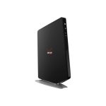
UfiSpace S9510-30XC Disaggregated Cell Site Gateway Router

Overview
- The UfiSpace S9510‐30XC is a high‐performance, versatile open networking white box router that is designed to address the changing needs of backhaul transport requirements as telecoms make the transition from legacy technologies towards 5G.
- It enables telecoms and service providers to deploy disaggregated open network infrastructure to lower costs and rapidly scale existing services for edge computing, mobile backhaul, and broadband access applications.
- The S9510‐30XC is future‐proofed with a powerful 4‐core processor, 25GE/100GE high‐speed interfaces, and full timing features supporting IEEE 1588v2 and SyncE, which enables service providers to easily migrate from 2G, 3G, 4G BBUs to 5G RAN. It is suitable for both indoor and outdoor deployments with redundant, hot swappable components for convenience, increased availability, reliability and lower costs of maintenance
- This document describes the hardware installation process for S9510‐30XC.
Preparation
Installation Tools

- PC with terminal emulation software. Refer to the “Initial System Setup” section for details.
- Baud rate: 115200 bps
- Data bits: 8
- Parity: None
- Stop bits: 1
- Flow control: None
Installation Environment Requirements
- Power Reserve: The S9510‐30XC power supply is available with:
- DC Version: 1+1 active‐active ‐36 to ‐75V DC power supply field replaceable unit or;
- AC Version: 1+1 active‐active universal 100 to 240V AC power supply field replaceable unit.
To ensure the active‐active feed power design functions properly, a field with a dual power circuit is recommended with a reserve of at least 400 watts on each power circuit.
- Space Clearance: The S9510‐30XC width is 17.32 inches (44cm) and shipped with rack mount brackets suitable for 19-inch (48.3cm) wide racks and adjustable mounting rails are provided for rack depths of 22 inches (55.9cm) to 33 inches (83.8cm). The depth of the S9510‐30XC chassis is 11.89 inches (30.2cm) without the field-replaceable units (FRUs). The handle for the fan units will extend outwards by 1 inch (2.5cm) and the handle for the power supplies will extend outwards by 1.06 inches (2.7cm). To accommodate the air inlet and front cabling, a recommended minimum space clearance of 6 inches (15.2cm) for the front of the unit. To accommodate the fan handle, it is recommended that a minimum space clearance of 1 inch (2.5cm) for the back of the unit. A total minimum reserve depth of 18.89 inches (47.9cm) is required.

- Cooling: The S9510‐30XC airflow direction is front‐to‐back. Make sure the equipment on the same rack have the same airflow direction.

Preparation Check List

Package Contents
Accessory List

Component Physical Information

Identifying Your System
S9510‐30XC Overview

DC Version PSU Overview
Power supply unit (PSU) with 1+1 redundancy. Hot swappable, field-replaceable unit (FRU).

AC Version PSU Overview
Power supply unit (PSU) with 1+1 redundancy. Hot-swappable, field-replaceable unit (FRU).

Fan Overview
4+1 Redundant, hot-swappable, field-replaceable unit (FRU).

Port Overview


Rack Mounting
 It is recommended that installation be done by two trained professionals. One individual should hold the equipment in position on the rack while the other secures it in place.
- Secure the rack mount brackets onto the router.
Align the rack mount brackets with the holes provided on the both sides of the case and secure the brackets using the 8 M4.0*L6.5mm screws provided with the package.
- Secure the router onto the rack posts.
Mark the location on both posts to ensure it is leveled before securing the router onto
the rack. (See Figure 11). For a 4 post rack, first secure the adjustable mounting rail to the back of the router using the M4.0*L6.5mm screws provided in the package. Then secure the adjustable mounting rail to the rack posts. (See Figure 12).
 Illustrations are for reference purposes only. Actual scenario may differ. Screws for rack posts not included.

Installing Fan Modules
The fan modules are hot swappable field replaceable units (FRUs), which can be replaced while the router is operating as long as all the remaining modules are installed and in operation. The fans come pre‐installed and the following steps are instructions on how to install a new fan module.
- Loosen the captive screw located on the fan module.

- Grip the fan’s handle and firmly pull it out of the fan bay.

- Align the new fan module with the fan bay.
- Carefully slide the new fan module into the fan bay and gently push until it is flush with the case.
- Secure the captive screw on the fan module to lock the fan in place.

Installing Power Supply Units
The power supply unit (PSU) is a hot-swappable field replaceable unit (FRU) and can be replaced while the router is operating as long as the remaining (second) PSU is installed and in operation. The PSUs come pre‐installed and the following are instructions on how to install a new PSU.

Shock hazard!
For safety, please disconnect all power inputs from the power supply unit before servicing the router.
- Locate the release tab on the PSU. Then press and hold down the release tab to unlock the PSU from the power bay.
- While holding down the release tab, grip the PSU’s handle and firmly pull it out of the power bay.

- Align the new PSU with the power bay, ensuring the PSU’s power connector is in the correct position.
- Carefully slide the new PSU into the power bay and gently push until it is flush with the case.
- An audible click will be heard when the PSU is installed correctly. The PSU will not go all the way if it is in the wrong direction.
Illustrations are for reference purposes only. Actual scenarios may differ.

Grounding the Router
It is recommended that equipment changes be done on a grounded rack system. This will reduce or prevent the risk of shock hazards, equipment damage, and potential of data corruption.
The router can be grounded from the router’s case and the power supply units (PSUs). When grounding the PSUs, ensure that both PSUs are grounded at the same time in case one of them is removed. A grounding lug, M4 screws, and washers are provided with the package contents, however, the grounding wire is not included. For convenience, there are two locations on the case in which the grounding lug may be fixed.
The following instructions are for grounding the router.
 This equipment must be grounded. Do not defeat the ground conductor or operate the equipment without correctly grounding the equipment. If there is any uncertainty about the integrity of the equipment’s grounding, please contact the electrical inspection authority or a certified electrician.
- Before grounding the router, ensure that the rack is properly grounded and in compliance with local regulatory guidelines. Ensure that there is nothing that can obstruct the connection for grounding and remove any paint or materials that may prevent good grounding contact.
- Strip the insulation from a size #6 AWG grounding wire (not provided within the package contents), leaving 0.5” +/‐0.02” (12.7mm +/‐0.5mm) of exposed grounding wire.
- Insert the exposed grounding wire all the way into the hole of the grounding lug (provided with package contents).
- Using a crimping tool, firmly secure the grounding wire to the grounding lug.

- Locate the designated location for securing the grounding lug, which is located on the side of the router.
- Using 2 M4 screws and 4 washers (provided with the package contents), firmly lock the grounding lug to either of the designated grounding locations on the router.

Connecting Power
DC Version
- Ensure there is enough power to supply the system.
The maximum system power consumption is 268 watts. It is recommended to ensure that enough power is reserved from the power distribution system before installation. Also, please ensure that both PSUs have been properly installed before powering up the equipment, as the S9510‐30XC is designed to support 1 + 1 power redundancy. - Attach the power cable.
Locate the DC power screw‐type terminal block on the DC PSU. Attach the UL 1015, 14 AWG DC power cable (not provided within the package contents) to the DC inlet connector on the PSU.
 Dangerous voltage!
- Must be powered off before removing!
- Verify that all electrical connections are grounded before powering on
- The DC power source must be reliably grounded

Tighten the screws to the specified torque.
Tighten the screws to a torque value of 7.0+/‐0.5kgf.cm. If the torque is not enough, the lug will not be secure and may cause malfunctions. If the torque is too much, the terminal block or lug may be damaged.

Feed DC power into the system.
The PSU will immediately output 12V and 5VSB to the system when a ‐36V to ‐75V DC power source is applied. The PSU has a built in 20 amperes, fast acting fuse based on the PSU maximum capacity, which will act as a second tier system protection in case the power distribution unit’s fuse is not functioning.
Verify that the power supply is operating.
If connected correctly, when turned on, the LED on the PSU will light up with a Green color designating normal operation.
AC Version
- Ensure there is enough power to supply the system.
The maximum system power consumption is 263 watts with an input voltage of 100‐240V AC. It is recommended to ensure that enough power is reserved from the power distribution system before installation. Also, please ensure that both PSUs have been properly installed before powering up the equipment, as the S9510‐30XC is designed to support 1 + 1 power redundancy. - Attach the power cable.
Plug the power cord into the AC PSU and secure it tightly. - Verify that the power supply is operating.
If connected correctly, when turned on, the LED on the PSU will light up with a Green color designating normal operation.

Verifying System Operation
Front Panel LED
Verify basic operations by checking the system LEDs located on the front panel. When operating normally, the PWR, FAN, and STAT LEDs should all display green.


PSU FRU LED

Fan FRU LED

Management port LED

Initial System Setup
Establishing a first‐time serial connection.
To assign an IP address, you must have access to the command line interface (CLI). The CLI is a text‐based interface that can be accessed through a direct serial connection to the device.
Access the CLI by connecting to the console port. After you assign an IP address, you can access the system through Telnet or SSH by Putty, TeraTerm or HyperTerminal.
Perform the following steps to access the device through a serial connection:
- Connect the console cable.
- The console can be connected using the RJ45 port labelled IOIO.
- To connect to console, plug a RJ45 serial cable into the console port and connect the other end to the computer. Cable types may vary depending on the model.

- Check for serial control availability.
Disable any serial communication programs running on the computer such as synchronization programs to prevent interference. - Launch a terminal emulator.
Open a terminal emulator application such as HyperTerminal (Windows PC), Putty or TeraTerm and configure the application. The following settings are for a Windows environment (other operating systems will vary):- Baud rate: 115200 bps
- Data bits: 8
- Parity: None
- Stop bits: 1
- Flow control: None
- Login to the device.
After the connection is established, a prompt for the username and password displays. Enter the username and password to access the CLI. The username and password should be provided by the Network Operating System (NOS) vendor.
Cable Connections
Connecting the USB Extender Cable
Connect the USB 3.0 A Type plug (male connector) into the USB port (female connector) located on the front panel of the router. The USB port is a maintenance port.

Connecting a Cable to the ToD Interface
The maximum length of the straight‐through Ethernet cable should not be more than 3 meters.
- Connect one end of a straight‐through Ethernet cable to the GNSS unit
- Connect the other end of the straight‐through Ethernet cable to the port marked “TOD” located on the front panel of the router.

Connecting a Cable to the BITS Interface
The maximum length of the BITS cable should not be more than 3 meters.
- Connect one end of a shielded RJ48 cable to the port labelled “BITS” located on the front panel of the router.
- Connect the other end of the cable to the BITS patch or demarcation panel.

- Below is the pinout for the BITS port.

Connecting the GNSS Interface
Connect an external GNSS antenna with an impedance of 50 ohms to the port marked “GNSS ANT” located on the front panel of the router.

Connecting the 1PPS Interface
The maximum length of the 1PPS coaxial SMB/1PPS Ethernet cable should not be more than 3 meters.
Connect an external 1PPS cable with an impedance of 50 ohms to the port labelled “ 1PPS”.

Connecting the 10MHz Interface
The maximum length of the 10MHz coaxial SMB cable should not be more than 3 meters.
Connect an external 10MHz cable with an impedance of 50 ohms to the port labelled “10MHz”.

Connecting the Transceiver
To prevent over-tightening and damaging the optic fibers, it is not recommended to use tie wraps with optical cables.
Read the following guidelines before connecting the transceiver:
- Before installing the router, take into consideration rack space requirements for cable management and plan accordingly.
- It is recommended to use hook‐and‐loop style straps to secure and organize the cables.
- For easier management, label each fiber‐optic cable and record its respective connection.
- Maintain a clear line of sight to the port LEDs by routing the cables away from the LEDs.
Before connecting anything (cables, transceivers, etc.) to the router, please ensure to discharge any static electricity that may have built up during handling. It is also recommended the cabling be done by a professional who is grounded, such as by wearing an ESD wrist strap.
Please follow the steps below for connecting a transceiver.
- Remove the new transceiver from its protective packaging.
- Remove the protective plug from the transceiver port.
- Place the bail (wire handle) in the unlocked position and align the transceiver with the port.
- Slide the transceiver into the port and use gentle pressure to secure it in place. An audible click can be heard when the transceiver is secured in the port.
Installing an Antenna
Make sure the satellite signal strength is greater than 30db, when using a GNSS simulator for testing.
Read the following guidelines before installing your antenna.
- The S9510‐30XC supports various types of receiver frequency types, including GPS L1C/A,GLONASS L1OF, BeiDou B1, and Galileo E1B/C.
- The minimum sensitivity of the receiver frequency (RF) is ‐166dBm.
- The S9510‐30XC supports both passive and active GNSS antennas, and will automatically detect which type of antenna is installed.
- If the received signal strength is lower than 30db, the GNSS receiver will fail to produce accurate location estimates.
To optimize antenna performance, it is highly recommended to choose a roof or top floor that is free from any signal blockage or obstruction.
Read the following guidelines before installing an active antenna:
- When an active antenna is installed, the S9510‐30XC can supply up to 5V DC/150mA on the GNSS port.
- If any GNSS amplifier, DC‐blocked or cascaded splitter is inserted, the GNSS detection function might be affected, resulting in GNSS satellite clock errors.
- We recommend that you use an active antenna equipped with 50 ohm impedance matching, 5V DC power supply capable, max. NF 1.5dB and 35~42dB internal LNA gain to get a strong enough signal strength in various weather conditions.
- To prevent damages caused by power surges or lightning strikes, ensure a surge protector is attached to the GNSS antenna.

Cautions and Regulatory Compliance Statements
 Safety Notices
Caution! Shock hazard!
TO DISCONNECT POWER, REMOVE ALL POWER CORDS FROM UNIT.
 Electrical Hazard: Only qualified personnel should perform installation procedures.
Warning: Network Switch power supplies do not have switches for turning the unit on and off. Before servicing, disconnect all power cords to remove power from the device. Make sure that these connections are easily accessible.
 Caution: Before mounting the device, ensure that the rack can support it without compromising stability. Otherwise, personal injury and/or equipment damage may result.
Caution: Use of controls or adjustments or performance of procedures other than those specified herein may result in hazardous radiation exposure.
Caution: Only Laser Class 1 optical transceivers shall be used.
Warning: Do not use optical instruments to view the laser output. The use of optical instruments to view laser output increases eye hazard. Use only UL/CSA, IEC/EN60825‐1/‐2 recognized pluggable modules.
Warning:
The equipment should only be used within a restricted access area.
The equipment should only be operated by skilled or instructed persons.
The equipment and its modules should only be repaired, maintained or replaced by skilled personnel.
Instructed person is a term applied to persons who have been instructed and trained by a skilled person, or who is supervised by a skilled person.
Class A ITE Notice
This equipment is compliant with Class A of CISPR 32. In a residential environment, this equipment may cause radio interference.
VCCI Notice
This is Class A equipment. Operation of this equipment in a residential environment could cause radio interference. In such a case, the user may be required to take corrective actions.
Cautions and regulatory compliance statements for NEBS:
- “An external Surge Protection Device (SPD) must be used with AC powered equipment and that the Surge Protection Device is to be installed at the AC power service entrance.”
- The design of the equipment is that the RTN terminal should be isolated from the chassis or rack. (The DC input terminals is DC‐I (Isolated DC return))
- “WARNING: The intra‐building port OOB (Ethernet) of the equipment or subassembly is suitable for connection to intra‐building or unexposed wiring or cabling only. The intrabuilding port(s) of the equipment or subassembly MUST NOT be metallically connected to interfaces that connect to the OSP or its wiring for more than 6 meters
(approximately 20 feet). These interfaces are designed for use as intra‐building interfaces only (Type 2, 4, or 4a ports as described in GR‐1089) and require isolation from the exposed OSP cabling. The addition of Primary Protectors is not sufficient protection in order to connect these interfaces metallically to an OSP wiring system.”
CONTACT
Documents / Resources
 |
UfiSpace S9510-30XC Disaggregated Cell Site Gateway Router [pdf] Installation Guide S9510-30XC Disaggregated Cell Site Gateway Router, S9510-30XC, Disaggregated Cell Site Gateway Router, Cell Site Gateway Router, Site Gateway Router, Gateway Router |