![]()
LIQUID LEAK DETECTION SYSTEMS Quick Start
Guide
FG-NET Digital Panel
Mounting the FG-NET Digital Panel
- Rack-mounted version: a 4U space is required within a 19” electrical equipment box.
- Wall-mounted version: affix to the wall (a stencil is provided for drilling the 4 fixing holes).
- We recommend fixing at a height between 5 ft (1.50m) and 6 ft (1.80m), to provide a comfortable height for viewing the touch-screen display.
- Open the cover of the wall-mounted panel to reach the motherboard as shown in the picture:
Electrical Connection
Power supply: 100 – 240 V AC, 50/60 Hz, 1.3 A, 50 W.
If possible, use a UPS power source. 3 x 16 AWG (1.5 mm²) multi-core electric cable.
IMPORTANT: To connect grounding of the box to earth: use standardized single-core 14 AWG (2.5 mm²) earth wire.
Connecting the Detection Circuits
Connect the 2 pairs of TTK BUS 8723 standard cable in each circuit, respecting the color code below:
A: Green wire, B: White wire, C: Black wire, D: Red wire
Plug each jumper cable into the cable clamp provided. Fix the shielding tightly to the cable clamp to ensure proper grounding.
CAUTION: A poor earth connection removes prevents the shielding from acting as an “electromagnetic screen”. Without the correct earthing, the system may develop faults and false readings. The correct earthing must be maintained. If any circuits are left unused, a shunt must be placed between A and B on the corresponding connector for that circuit, if one is not already there. At no time may a shunt be put between C and D. For more details, refer to the wiring diagram attached to the inside of the FG-NET panel.
Powering up the FG-NET
Close cover before powering up:
During power-up, the panel displays the homepage after the start-up is complete. To set up the panel, go to the “Setup” menu.
System Settings
Menu “Setup” > tab “system”:
- Change the application language
- Set the date and time
- Create the user accounts and modify the administrator password.
Setting the cables and relays 
Menu “Cables” on Homepage > “Edit” button on each sense cable allows cables and relays to be configured.
- Name the cables according to the rooms in which they are installed. If several cables protect the same room, we recommend combining these cables together. Combining the cables will give them all the same name and a cumulative length in meters for the leak location display.
- Configure the general relay and the leak and/or cable break relays.
Verifying the architecture settings
The “cables” menu on the homepage allows the architecture of the installation to be displayed together with the floor plan associated with each “zone” (optional function).
Leak Tests and Simulations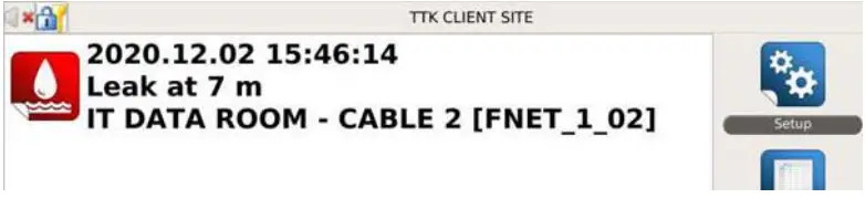
The leak tests and simulations are important for:
- Verifying the operation of the system
- Checking the designation of the cables
- Verifying consistency between the «as-installed» drawings and the actual floor plan of the installation.
Carry out simulations throughout the installation on all 9ft, 22ft, and 49ft (3m, 7m, and 15m) cables to ensure that all are functioning fully and communicating correctly with the panel.
In particular, a leak simulation is necessary for the areas deemed at-risk (such as air-conditioning, valves, bathrooms, condensation, low points, etc).
TIP: The complete installation notice for this product can be downloaded on TTK’s website by scanning the QR code.
For more information, go to www.ttkuk.com; www.ttkusa.com; www.ttkasia.com.
QSG_FG-NET_EN_US_FR_v2.0.2_062021
Documents / Resources
 |
TTk FG-NET Digital Panel [pdf] User Guide FG-NET, Digital Panel, FG-NET Digital Panel |


