truflo TKB-40-PP-B In-Line Paddle Wheel Flow Meter Sensor

Product Information
Specifications
- Linearity: 10 : 1
- Repeatability: Fluid
Product Usage Instructions
Installation Guidelines
The TK Series flow meter can be installed horizontally or vertically. Ensure a minimum of 10x pipe diameters upstream and 3x pipe diameters downstream for accurate readings. Use a Bag Filter or Y Strainer upstream to prevent damage from solids or fibers. Avoid flushing the pipe with compressed air after installation to prevent damage to the ceramic shaft.
FAQ
- Q: Can the flow meter be installed vertically?
A: Yes, the TK Series flow meter can be installed in both horizontal and vertical directions. - Q: What is the maximum operating pressure of the flow meter?
A: The flow meter can operate at a maximum pressure of 150 Psi (10 Bar) at ambient temperature without shock. - Q: What type of fluids is the flow meter suitable for?
A: The flow meter is suitable for water or chemical liquids within a viscosity range of 0.5-20 centistokes.
Safety Information
- De-pressurize and vent system prior to installation or removal
- Confirm chemical compatibility before use
- DO NOT exceed maximum temperature or pressure specifications
- ALWAYS wear safety goggles or face-shield during installation and/or service
- DO NOT alter product construction
![]() Warning | Caution | Danger
Warning | Caution | Danger
Indicates a potential hazard. Failure to follow all warnings may lead to equipment damage, injury, or death.
![]() Note | Technical Notes
Note | Technical Notes
Highlights additional information or detailed procedure.
 Personal Protective Equipment (PPE)
Always utilize the most appropriate PPE during installation and service of Truflo® products.
Take caution as the sensor may be under pressure. Vent the system prior to installation or removal to avoid equipment damage and injury.
 Pressurized System Warning
Sensor may be under pressure. Take caution to vent system prior to installation or removal. Failure to do so may result in equipment damage and/or serious injury.
Please ensure that the Instruments are not to be subject to water hammer or pressure spikes! Always Pressure Test System with H2O Prior to Initial Start-Up
Before installation be certain the appropriate instrument has been selected considering operating pressure, full scale pressure, wetted material requirements, media compatibility, operating temperature, vibration, pulsation, desired accuracy and any other instrument component related to the service application including the potential need for protective attachments and/or special installation requirements. Failure to do so could result in equipment damage, failure and/or personal injury.
Ensure only qualified personnel are permitted to install and maintain this instrument.
Pressurize System Warning
Sensor may be under pressure, take caution to vent system prior to installation or removal. Failure to do so may result in equipment damage and/or serious injury.
Please Ensure Full Pipe
TK Series can be installed in a horizontal or vertical direction. Please ensure enough length of straight pipe to avoid turbulence that can effect readings.
Min 10x Pipe Diameters Upstream 3x Pipe Diameters Downstream
A Bag Filter or Y Strainer Filtering Device upstream to Avoid the Paddle Wheel from being damaged by the solids or fibers – max 10% Particle Size – Not to Exceed .5mm Cross Section or Length. Please do not flush the pipe after the Flow Meter is installed with compressed air this may damage the ceramic shaft and will void warranty.
Product Description
It features a contoured flow profile, reduced turbulence for increased longevity, and high wear resistance. The TK Series in-line plastic paddle wheel flow meter has been engineered to provide long-term accurate flow measurement in tough industrial applications. The paddle wheel assembly consists of a engineered Tefzel® paddle and micro-polished zirconium ceramic rotor pin and bushings. High performance Tefzel® and Zirconium materials have been selected due to their excellent chemical and wear resistant properties.

Features
- ½” – 4” Line Sizes
- Flow Rate | Total
- TK3B Sanitary Connection
- Zirconium Ceramic Rotor | Bushings for increased wear resistance
- True Union Design with high impact enclosure
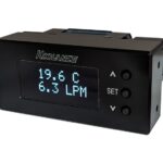
- Bright LCD Display for flow and total readings
- Flanged Connection for easy installation
New ShearPro® Design
- Contoured Flow Profile
- Reduced Turbulence = Increased Longevity
- 78% Less Drag than Old Flat Paddle Design* *Ref: NASA “Shape Effects on Drag”


Technical Specifications
| General | ||
| Operating Range | 0.3 to 33 ft/s | 0.1 to 10 m/s |
| Pipe Size Range | ¼ to 4″ ** | DN08 to DN100 |
| Linearity | ±0.5% of F.S @ 25°C | 77°F | |
| Repeatability | ±0.5% of F.S @ 25°C | 77°F | |
| Fluid | Water or Chemical Liquid-Viscosity Range: 0.5-20 centistokes | |
| Flow Velocity | 10 m/s max. | |
| Low Cut | 0.3 m/s min. | |
| Operating Pressure | 150 Psi (10 Bar) @ Ambient Temp | Non-Shock | |
| Range Ability | 10 : 1 | |
| Response Time | Real Time | |
| Flow Total Meter | Range = 0~999999 ; Unit = Gallon or Liter or Ton (KL) Selectable | |
| Repeatability | Range = 0.0~999.9 ; Unit = GPM or LPM or CMH Selectable | |
| Accuracy | ± 0.5% of F.S. @ 25°C | |
| Wetted Materials | ||
| Sensor Body | PVC (Dark) | PP (Pigmented) | PVDF (Natural) | |
| O-Rings | FKM | EPDM* | FFKM* | |
| Rotor Pin | Bushings | Zirconium Ceramic | ZrO2 | |
| Paddle | Rotor | ETFE Tefzel® | |
| Electrical | ||
| Operating Voltage Battery | 3.0 VDC | |
| Battery | Lithium Battery (CR2477T) | |
| Life of Battery | >1 Year Normal | >2 Years Eco Mode | |
| Max. Temperature/Pressure Rating – Standard and Integral Sensor | Non-Shock | ||
| PVC | 180 Psi @ 68°F | 40 Psi @ 140°F | 12.5 Bar @ 20°C | 2.7 Bar @ 60°C |
| PP | 180 Psi @ 68°F | 40 Psi @ 190°F | 12.5 Bar @ 20°C | 2.7 Bar @ 88°C |
| PVDF | 200 Psi @ 68°F | 40 Psi @ 240°F | 14 Bar @ 20°C | 2.7 Bar @ 115°C |
| 316 SS | 200 Psi @ 180°F | 40 Psi @ 300°F | 14 Bar @ 82°C | 2.7 Bar @ 148°C |
| Operating Temperature | ||
| PVC | 32°F to 140°F | 0°C to 60°C |
| PP | -4°F to 190°F | -20°C to 88°C |
| PVDF | -40°F to 240°F | -40°C to 115°C |
| 316 SS | -40°F to 300°F | -40°C to 148°C |
| Display | ||
| LCD | Flow Rate + Flow Totalizer | ||
| Standards and Approvals | ||
| UL | CE | FCC | RoHS Compliant | ||
See Temperature and Pressure Graphs for more information
Model Selection
| PVC | ||
| Size | End Connections | Part Number |
| ½” | Sch 80 Soc | TKB-15-P |
| ¾” | Sch 80 Soc | TKB-20-P |
| 1” | Sch 80 Soc | TKB-25-P |
| 1 ½” | Sch 80 Soc | TKB-40-P |
| 2” | Sch 80 Soc | TKB-50-P |
| 3” | Flanged | TKB-80-P |
| 4” | Flanged | TKB-100-P |
Add 1st Suffix (end connection):
- T ▶ NPT End Connectors (on PVC)
- B ▶ Butt Fused End Connections for PP or PVDF
- F ▶ Flange ANSI 150lb – Consult Factory
| PP | ||
| Size | End Connections | Part Number |
| ½” | NPT | TKB-15-PP |
| ¾” | NPT | TKB-20-PP |
| 1” | NPT | TKB-25-PP |
| 1 ½” | NPT | TKB-40-PP |
| 2” | NPT | TKB-50-PP |
| 3” | Flanged | TKB-80-PP |
| 4” | Flanged | TKB-100-PP |
Add 2nd Suffix (seals):
FKM (std, no suffix required)
- E ▶ EPDM Seals
- K ▶ FFKM | Kalrez® Seals
| PVDF | ||
| Size | End Connections | Part Number |
| ½” | NPT | TKB-15-PF |
| ¾” | NPT | TKB-20-PF |
| 1” | NPT | TKB-25-PF |
| 1 ½” | NPT | TKB-40-PF |
| 2” | NPT | TKB-50-PF |
Note:PVC Socket Ends (Std)
PP/PVDF NPT Ends (Std)
| 316 SS | ||
| Size | End Connections | Part Number |
| ¼” | NPT | TK3B-08-SS |
| ⅜” | NPT | TK3B-10-SS |
| ½” | NPT | TK3B-15-SS |
| ¾” | NPT | TK3B-20-SS |
| 1” | NPT | TK3B-25-SS |
| 1 ½” | NPT | TK3B-40-SS |
| 2” | NPT | TK3B-50-SS |
| 3” | NPT | TK3B-80-SS |
| 4” | NPT | TK3B-100-SS |
Add 1st Suffix (end connection):
- T ▶ NPT End Connectors
- SE ▶ Sanitary – Consult Factory for Pricing
- F ▶ Flange ANSI 150lb – Consult Factory
Add 2nd Suffix (seals):
FKM (std, no suffix required)
- E ▶ EPDM Seals
- K ▶ FFKM | Kalrez® Seals
Exploded View


| 1 | Polycarbonate Cover |
| 2 | Flow Controller |
| 3 | Hall Pickup Sensor |
| 4 | Redesigned Rotor Assembly |
| 5 | Body – PVC | PP | PVDF |
| 6 | Reinforced Inserts |
| 7 | ShearPro® Paddle Wheel |
| 8 | Rotor Bushings |
| 9 | Rotor Pin |


Programming
![]()


Flow Totalizer
Display the Current Value of Flow Totalizer : Range 0~99,999,999
- Hold the
 key for 3 seconds to show current value of the 7th – 8th digits
 - After releasing the key the current value of the 1st – 6th digits will be displayed
Flow | Totalizer Reset Lock
How to Set the Flow/Totalizer Reset Lock?
The Flow Total | Totalizer can be protected from an accidental reset. To set lockout program set any number from 0-8. The factory default unlock number 9.
Totalizer Reset → Press both ![]() keys together for
keys together for ![]()
Low Battery Notification
| Voltage of Battery | Symbol | Status |
| 3.0V |  |
Full Scale |
| < 3.0V | Mild Scale | |
| < 2.8V |  |
Low Scale (Pilot BAT Flashing) |
| < 2.6V |  |
Low Voltage (Pilot BAT & Display Flashing) |
Displaying Flow Rate | Flow Totalizer

K-Factors for TK Series
| Size | K-Factor |
| ¼” | 547 |
| ⅜” | 300 |
| ½” | 124 |
| ¾” | 72 |
| 1” | 54 |
| 1½” | 19 |
| 2” | 10.3 |
| 3” | 4.7 |
| 4” | 2.1 |
| ⚠ K-Factor is Pre-Programmed | |
Min/Max Flow Rates

Pressure vs. Temperature Psi H2O | Non-Shock
| Nominal Size | PVC | PP | PVDF | |||||||||||
| 30º F | 71º F | 106º F | 121º F | -5º F | 86º F | 121º F | 141º F | -5º F | 71º F | 106º F | 141º F | 176º F | ||
| Inches | mm | 70º F | 105º F | 120º F | 140º F | 85º F | 120º F | 140º F | 175º F | 70º F | 105º F | 140º F | 175º F | 210º F |
| ½ – 2 | 15-50 | 150 | 120 | 100 | 30 | 150 | 110 | 90 | 55 | 150 | 125 | 100 | 85 | 55 |
| 2½ | 65 | 150 | 120 | 100 | NA | 150 | 95 | 70 | 40 | 150 | 125 | 100 | 85 | 55 |
| 3 | 80 | 150 | 120 | 100 | NA | 150 | 95 | 70 | 40 | 150 | 125 | 100 | 85 | 60 |
| 4 | 100 | 150 | 120 | 100 | NA | 150 | 95 | 70 | 40 | 150 | 125 | 100 | 85 | 60 |
Dimensions


Battery Replacement
- Lightly Press on both Sides Battery Cover.
 Remove the Battery Cover.
- Remove the Battery.

- Insert the New Battery Ensure (+ -) orientation is correct.

Procedure to Rotate Display
- Use an Allen key toloosen the screws located on both side of the display.

- Lightly pull on the screws in an outwards direction. Screws are Captive – Do Not Completely Remove!

- Lift the display.
 Rotate Display.
- Reposition the Display.

- Tighten (Snug) the Allen Screws both Sides.

Installation Position


Please Ensure Full Pipe
TK Series can be installed in a horizontal or vertical direction.
Please ensure enough length of straight pipe to avoid turbulence that can effect readings.
Note: Min 10x Pipe Diameters Upstream 3x Pipe Diameters Downstream.
A Plastic Basket Strainer, Bag Filter or Y Strainer Filtering Device upstream to Avoid the Paddle Wheel from being damaged by the solids or fibers – max 10% Particle Size – Not to Exceed .5mm Cross Section or Length. Please do not flush the pipe after the Flow Meter is installed with Compressed Air this may damage the ceramic shaft and will Void Warranty.
Warranty, Returns and Limitations
Warranty
Icon Process Controls Ltd warrants to the original purchaser of its products that such products will be free from defects in material and workmanship under normal use and service in accordance with instructions furnished by Icon Process Controls Ltd for a period of one year from the date of sale of such products. Icon Process Controls Ltd obligation under this warranty is solely and exclusively limited to the repair or replacement, at Icon Process Controls Ltd option, of the products or components, which Icon Process Controls Ltd examination determines to its satisfaction to be defective in material or workmanship within the warranty period. Icon Process Controls Ltd must be notified pursuant to the instructions below of any claim under this warranty within thirty (30) days of any claimed lack of conformity of the product. Any product repaired under this warranty will be warranted only for the remainder of the original warranty period. Any product provided as a replacement under this warranty will be warranted for the one year from the date of replacement.
Returns
Products cannot be returned to Icon Process Controls Ltd without prior authorization. To return a product that is thought to be defective submit a customer return (MRA) request form and follow the instructions therein. All warranty and non-warranty product returns to Icon Process Controls Ltd must be shipped prepaid and insured. Icon Process Controls Ltd will not be responsible for any products lost or damaged in shipment.
Limitations
This warranty does not apply to products which:
- Are beyond the warranty period or are products for which the original purchaser does not follow the warranty procedures outlined above;
- Have been subjected to electrical, mechanical or chemical damage due to improper, accidental or negligent use;
- Have been modified or altered;
- Anyone other than service personnel authorized by Icon Process Controls Ltd have attempted to repair;
- Have been involved in accidents or natural disasters; or
- Are damaged during return shipment to Icon Process Controls Ltd
Icon Process Controls Ltd reserves the right to unilaterally waive this warranty and dispose of any product returned to Icon Process Controls Ltd where:
- There is evidence of a potentially hazardous material present with the product;
- Or the product has remained unclaimed at Icon Process Controls Ltd for more than 30 days after Icon Process Controls Ltd has dutifully requested disposition.
This warranty contains the sole express warranty made by Icon Process Controls Ltd in connection with its products. ALL IMPLIED WARRANTIES, INCLUDING WITHOUT LIMITATION, THE WARRANTIES OF MERCHANTABILITY AND FITNESS FOR A PARTICULAR PURPOSE, ARE EXPRESSLY DISCLAIMED. The remedies of repair or replacement as stated above are the exclusive remedies for the breach of this warranty. IN NO EVENT SHALL Icon Process Controls Ltd BE LIABLE FOR ANY INCIDENTAL OR CONSEQUENTIAL DAMAGES OF ANY KIND INCLUDING PERSONAL OR REAL PROPERTY OR FOR INJURY TO ANY PERSON. THIS WARRANTY CONSTITUTES THE FINAL, COMPLETE AND EXCLUSIVE STATEMENT OF WARRANTY TERMS AND NO PERSON IS AUTHORIZED TO MAKE ANY OTHER WARRANTIES OR REPRESENTATIONS ON BEHALF OF Icon Process Controls Ltd. This warranty will be interpreted pursuant to the laws of the province of Ontario, Canada. If any portion of this warranty is held to be invalid or unenforceable for any reason, such finding will not invalidate any other provision of this warranty.
Find Quality Products Online at: info@valuetesters.com
Documents / Resources
 |
truflo TKB-40-PP-B In-Line Paddle Wheel Flow Meter Sensor [pdf] Instruction Manual TKB-40-PP-B In-Line Paddle Wheel Flow Meter Sensor, TKB-40-PP-B, In-Line Paddle Wheel Flow Meter Sensor, Paddle Wheel Flow Meter Sensor, Flow Meter Sensor, Meter Sensor |