Trimble GS075-B-V2 Anti Two Block Switch User Manual
Features:
- Anti-Two-Block Switch
- Sealed switch mechanism
- Mechanism life over 250,000 cycles
- Malleable cast iron and stainless-steel enclosure
- Line of sight radio range of 4000 ft (1300m)
- Two ways radio communications
- Operates from one ‘D’ cell battery lithium 3.6V or alkaline 1.5V.
- 3 to 4 years battery life for typical applications
- ISM License free band with wavelength and modulation optimized for radio communication in industrial environment.
- Temperature range: -40°C to 65°C (-40°F to 150°F)
- Potted electronics for increase waterproof protection
- Class 1 division 1 option available
Applications:
- Anti-two-block limit switch.
General Description:
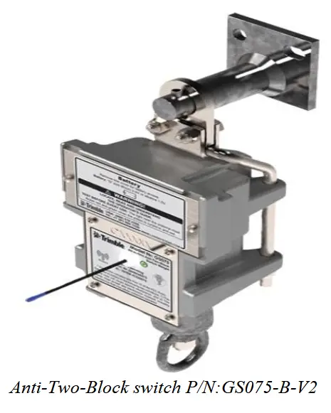
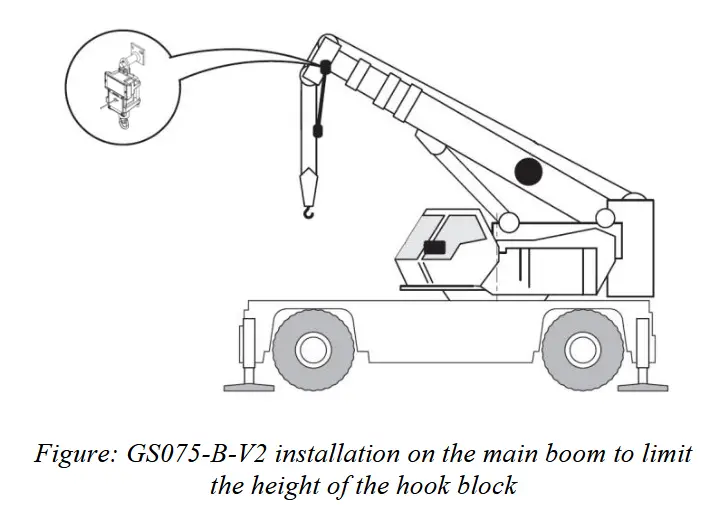
The anti-two-block switch comprises of the radio transmitter, battery and switch mechanism. The switch mounts at the boom tip. A weight and chain assembly is attached to the bottom eyebolt of the A2B switch. When the weight assembly is lifted by the ball/block, the internal switch in the A2B will trip an alarm, warning the operator of a two-block event.
The switch mounting bracket design allows the switch to rotate in two axis. The quick slip design of the mounting bracket allows the switch to easily be added or removed from the switch mounting bracket without the need for tools.
Ordering information

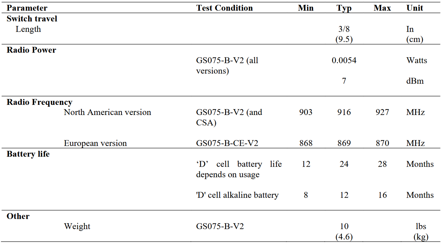
Specifications
Absolute maximum ratings

Certifications
FCC/IC/CE certification : FCC Part 15 Subpart C 15.247,15.205, 15.207 & 15.209
ETSI EN 300 220 (AA)
EMI/C – EN 61000-4-3, EN 61000-4-2
CSA certificate number – 80130757
CSA C22.2 No. 60079-0:19, 60079-11:14 (R2018), 61010-1-12, Update 1&2, Amd1:2018
UL 60079-0-2020, UL 60079-11-2018, UL 61010-1-2018
Class I, Division 1, Group A, B, C & D T4
Ex ia IIC T4 Ga
Class I, Zone 0, AEx ia IIC T4 Ga
Ambient Temperature: -20°C to 40°C.
![]() WARNING: Only use Tadiran TL-5930 3.6V or Saft LS33600 cell 3.6V text.
WARNING: Only use Tadiran TL-5930 3.6V or Saft LS33600 cell 3.6V text.
Dimensions and installation
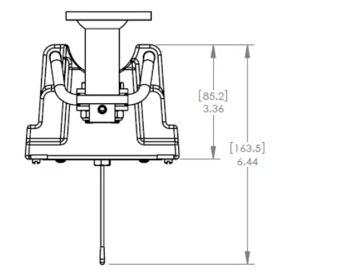
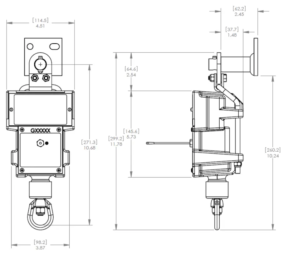
A2B Switch (not to scale)

Position the sensor mounting bracket (LB011). To ensure that the sensor can pivot securely on the mounting bracket throughout the full range of boom angle, the mounting bracket must be positioned at a 30° from horizontal with the boom parallel to the ground and such that the locking pin of the mounting bracket points up.
Install the GS075-B-V2 on the LB011 (switch bracket) already installed on the crane boom, with the antenna pointing away from the boom. Install a weight and chain assembly to the eye nut. The weight and chain assembly can either be supplied by LSI (as an option) or the original assembly supplied with the crane. If the original assembly is to be used, its total weight must not be more than 13lb.
PMN: GS075-B-V2
HVIN: MB114-01-SD-A
FCC Compliance Statement (USA)
FCC ID: S9E-GS200E
Compliance Statements: This device complies with Part 15 of the FCC Rules. Operation is subject to the following two conditions:
- This device may not cause harmful interference.
- This device must accept any interference received, including, an interference that may cause undesired operation.
Caution Statements:
- Any changes or modifications not expressly approved by the party responsible for compliance could void the user’s authority to operate this equipment.
- This equipment should be installed and operated with a minimum distance of 20 cm between the radiator and your body.
Industry Canada (IC) Compliance Statement
IC: 5817A-GS000E
Compliance Statements: This device complies with Industry Canada license-exempt RSS standard(s). Operation is subject to the following two conditions: 1) This device may not cause interference., 2) This device must accept any interference, including interference that may cause undesired operation of the device.
Caution Statements:
- This equipment complies with radio frequency exposure limits set forth by Industry Cananda for an uncontrolled environment.
- This equipment should be installed and operated with a minimum distance of 20 cm between the device and the user or bystanders.
Information to the Use
NOTE: This equipment has been tested and found to comply with the limits for a Class B digital device, pursuant to part 15 of the FCC Rules. These limits are designed to provide reasonable protection against harmful interference in a residential installation. This equipment generates, uses and can radiate radio frequency energy and, if not installed and used in accordance with the instructions, may cause harmful interference to radio communications. However, there is no guarantee that interference will not occur in a particular installation. If this equipment does cause harmful interference to radio or television reception, which can be determined by turning the equipment off and on, the user is encouraged to try to correct the interference by one or more of the following measures:
- Reorient or relocate the receiving antenna.
- Increase the separation between the equipment and receiver.
- Connect the equipment into an outlet on a circuit different from that to which the receiver is connected.
- Consult the dealer or an experienced radio/TV technician for help.
Documents / Resources
 |
Trimble GS075-B-V2 Anti Two Block Switch [pdf] User Manual GS200E, S9E-GS200E, S9EGS200E, GS075-B-V2 Anti Two Block Switch, GS075-B-V2, Anti Two Block Switch, Switch |