DSC PC585 Wiring Trikdis GT Cellular Communicator and Programming the Panel
CAUTION
- The communicator should be installed and maintained by qualified personnel.
- Prior to installation, it is advised to read full device installation manual carefully in order to avoid mistakes that can lead to malfunction or even damage the equipment.
- Disconnect the power supply before making any electrical connections.
- Changes, modifications or repairs not authorized by the manufacturer shall void your rights under the warranty.
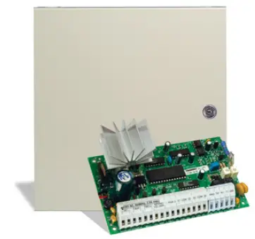
Schematics forwiring the communicator to the security control panel
Following the schematics provided below, wire the communicator to the control panel. DSC PC585 panel do not need to be programmed.
LED indication of communicator operation
| Indicator | Light status | |
|
NETWORK |
Off | No connection to cellular network |
| Yellow blinking | Connecting to cellular network | |
| Green solid with yellow blinking | Communicator is connected to cellular network.
Yellow blinks count indicates signal strength, 10 blinks max. Sufficient cellular signal strength for 4G network – level 3 (three yellow flashes). |
|
| DATA
|
Off | No unsent events |
| Green solid | Unsent events are stored in buffer | |
| Green blinking | (Configuration mode) Data is being transferred to/from communicator | |
| POWER
|
Off | Power supply is off or disconnected |
| Green solid | Power supply is on with sufficient voltage | |
| Yellow solid | Power supply voltage is insufficient (≤11.5V) | |
| Green solid and yellow blinking | Configuration mode) Communicator is ready for configuration | |
| Yellow solid | (Configuration mode) No connection with computer | |
| TROUBLE
|
Off | No operation problems |
| 1 red blink | SIM card not found | |
| 2 red blinks | SIM card PIN code problem (incorrect PIN code) | |
| 3 red blinks | Programming problem (No APN) | |
| 4 red blinks | Registration to GSM network problem | |
| 5 red blinks | Registration to GPRS/UMTS network problem | |
| 6 red blinks | No connection with the receiver | |
| 7 red blinks | Lost connection with control panel | |
| 8 red blinks | The entered ICCID number does not match the ICCID number of the SIM card | |
| Red blinking | (Configuration mode) Memory fault | |
| Red solid | (Configuration mode) Firmware is corrupted | |
|
BAND |
1 green blink | None |
| 2 green blinks | GSM | |
| 3 green blinks | GPRS | |
| 4 green blinks | EDGE | |
| 5 green blinks | HSDPA, HSUPA, HSPA+, WCDMA | |
| 6 green blinks | LTE TDD, LTE FDD |
Setting up the GT+ communicator with the app
Download and launch the Protegus application or use the browser version: web.protegus.app. The installer must connect to Protegus with an installer account.
Step 1

Click the “Add new system” button
Step 2
Enter the IMEI number of the communicator
Step 3
Select security company
Step 4
Press “DSC”
Step 5
Press “PC585”

Step 6
Enter “Object ID” and “Module ID”. Press “NEXT”
Step 7
Press “Add to Protegus2”
Step 8
Wait while the configuration is written
Step 9

Enter system “Name”. Press “Next”
Step 10
Press “Skip”
Step 11
Press on system
Step 12
Wait 1 minute and press “Transfer”
Enter system “Name”.
Press “Next” Press “Skip” Press on system Wait 1 minute and press “Transfer”

After completing the setup and installation perform a system check:
- Create an event:
- by arming/disarming the system with the control panel’s keypad;
- by triggering a zone alarm when the security system is armed.
- Make sure that the event arrives to the CMS (Central Monitoring Station) and the Proteg us app.
Documents / Resources
 |
TRIKDIS DSC PC585 Wiring Trikdis GT Cellular Communicator and Programming the Panel [pdf] Instructions DSC PC585, DSC PC585 Wiring Trikdis GT Cellular Communicator and Programming the Panel, Wiring Trikdis GT Cellular Communicator and Programming the Panel, Trikdis GT Cellular Communicator and Programming the Panel, GT Cellular Communicator and Programming the Panel, Communicator and Programming the Panel, Programming the Panel, Panel |


