TRIANGO 100 C Dual LED Ceiling Mounted Procedure Light
FAQs
- Q: How often should I clean the product?
- A: It is recommended to clean and disinfect the product at least once a week for optimal hygiene.
- Q: Can I disassemble the product on my own?
- A: Disassembly should be done following the provided instructions to avoid damage or improper disposal.
- Q: What should I do if the product malfunctions during operation?
- A: Refer to the troubleshooting section in the manual or contact customer support for assistance.
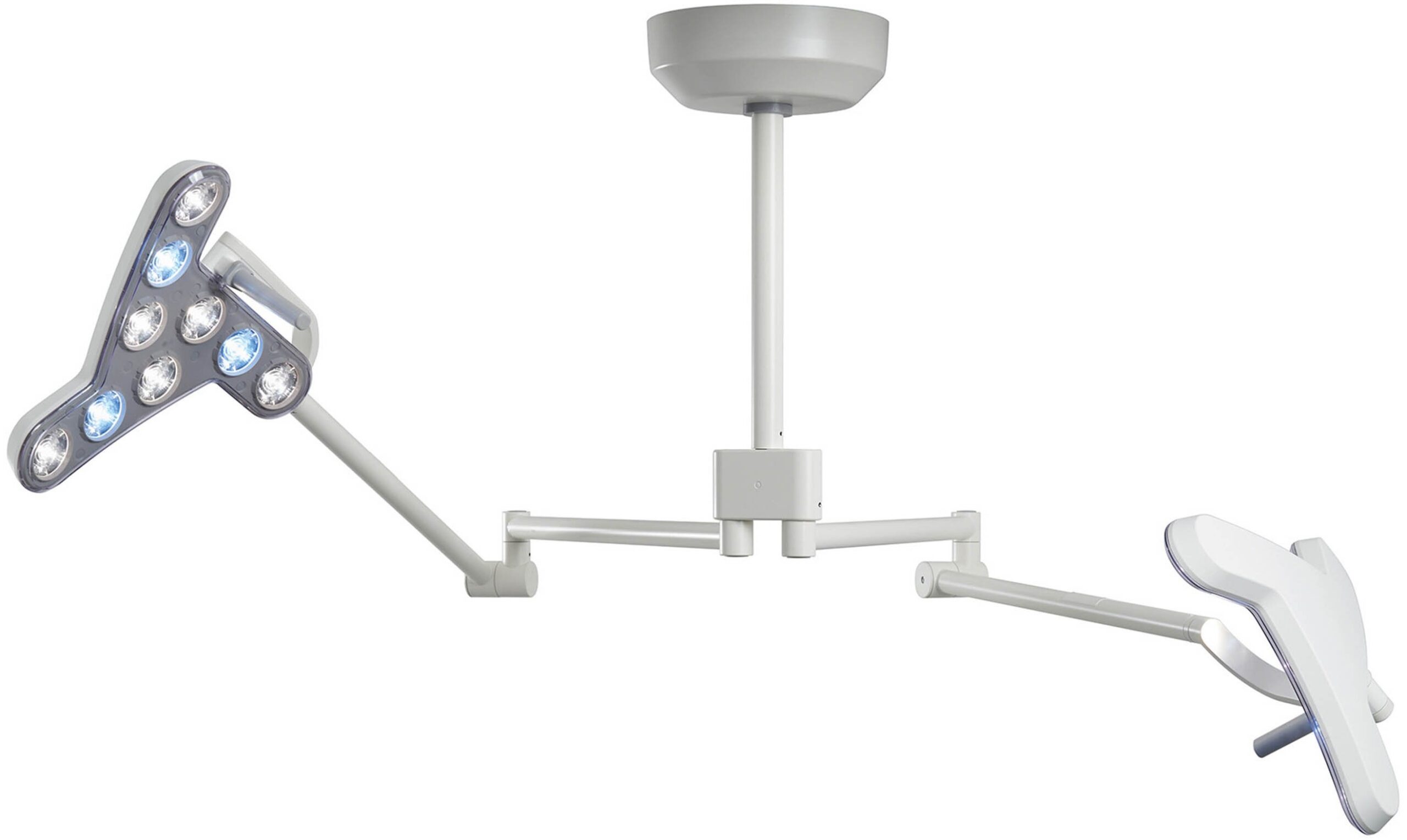
SCOPE OF SUPPLY
Scope of supply

- A: Ceiling bracket, ceiling cover, and end ring
- B: Ceiling tube
- C: Bearing head
- D: Ceiling arm
- E: Luminaire head with a sterilizable hand grip
SAFETY INSTRUCTIONS
Intended use
The TRIANGO 100 luminaire is a treatment lamp (small surgical lamp). It is a duo-lamp for use in operating rooms that is used near the patient to assist in diagnosis or treatment, which does pose any risk to the patient if a light failure causes an interruption. The duo ceiling system for a second luminaire head is used in various areas. For example, in the area of veterinary surgery, to achieve shadow-free illumination of larger wound areas. A second luminaire head offers additional redundancy which increases safety in intervention/ emergency rooms. It can also become necessary to illuminate two intervention locations on patients.
User profiles
- Health professional
- All individuals who have completed medical training and work in the professional field they trained for.
- Cleaning Specialist
- Trained in national and workplace hygiene regulations.
- Professional electrician
- Trained in electronics and electrical technology and knows the relevant standards and regulations.
- Qualified specialist
- Qualified due to his technical training, knowledge and experience, and knowledge of the rules, to perform assembly/dismantling.
Safety instructions
- Operation by health professionals
- This manual is part of the product and must be stored and made available to all future users.
- The assembly sequence must be observed.
- All work on the luminaire (including repairs) must be performed only by a qualified electrician. Assembly is to be done only by a qualified specialist.
- The luminaire may not be altered or tampered with. Only approved original parts may be used. Any use other than that intended, using original parts, can change technical parameters and pose a death hazard.
- Do not exceed the maximum weight and do not hang, lean, or climb on the arm, because the device will bedamaged or fall, which could result in serious injury.
- Operation in potentially explosive areas is prohibited. The luminaire’s current supply is a potential ignition source.
- The luminaire must be used only in dry, dust-free rooms.
- The luminaire must not be left switched on unattended.
- Only connect the luminaire to the supply network with a protective ground conductor (PE), to prevent electrical shock.
- In the case of luminaires of protection class I, the protective ground conductor (PE) must be connected to the luminaire housing.
- Do not use a damaged luminaire. Defective cables and a defective hand grip also pose a potential hazard. Do not place a cord near heat sources or sharp edges.
- Do not place extra loads on the luminaire head and arm system.
- The luminaire must not be covered with a cloth or similar item during operation.
- The ventilation openings (if present) must always be kept clear during operation!
- The luminaire must not be operated near external heat sources that exceed the luminaire’s maximum ambient temperature.
- The luminaire must not be used outside the specified ambient conditions.
- Do not use medical devices that may react sensitively to a light spectrum within the visible range (such as pulsating light and/or light with high illumination intensity).
- The luminaire may only be used for the intended use described here.
- The manufacturer cannot be held responsible for any damages resulting from use deviating from the intended use, or failure to observe the safety instructions and warnings.
- When using more than one luminaire at the same time, the total illumination intensity must not exceed Ee 1000W/m².
- Before connecting to the power grid, it is essential to check that the grid data matches the device data.
- The light fields of the individual luminaire heads must not overlap. Overlapping can exceed the upper limit of 160klx of the central illumination strength and increase the risk of tiring the eyes.
Warning levels
| DANGER |
| Warning of hazards that may result in death or serious injury if instructions are not followed. |
| WARNING |
| Warning of hazards that may result in injury if instructions are not followed. |
| CAREFUL |
| Warning of hazards that may cause material damage if instructions are not followed. |
Specific fastening instructions
Triangle 100 C Duo
- Fastening hardware does not come with delivery.
- The ceiling mount must only be mounted on ceilings with a concrete stability class of B25 (C20/25) or higher.
- There should be no contact with reinforcement parts of the solid ceiling during mounting. When in doubt, a licensed technician must approve installation on the specific installation surface.
- The load-bearing capacity of the ceiling structure must be planned, checked, and confirmed by a structural engineer beforehand.
- The holes must be drilled by a professional in compliance with the drilling tolerances permitted by the manufacturer of the fastening anchor. If a drilling error occurs, such as drilling into a reinforcement bar, a structural engineer must be consulted.
- Install the luminaire in such a way that the vertical and side stops are not continuously stressed during operation.
- With plaster or cladding in front of the concrete, the fastening anchor must be driven completely into the concrete.
- The screws must be tightened carefully using a torque wrench according to the specifications of the fastening anchor manufacturer.
ASSEMBLY
ASSEMBLY: Triango 100 C Duo
Workload data
| Bending moment MB | 490 Nm |
| Vertical weight FG | 300 N |
Shortening the ceiling tube

- Before shortening the ceiling tube, remove the cable from the ceiling tube.
- Shorten the steel ceiling tube at the upper end (the side without boreholes) to the required length and deburr.
Drilling the fastening holes of the ceiling tube

- When determining the location of the holes, ensure that the boreholes are aligned with the existing holes at the lower end of the pipe.

- Remove the fastening screw «C».
- Insert the ceiling tube «A» into the ceiling bracket «B» and drill the ceiling holder’s existing hole to 9 mm in diameter. Drill the opposite hole separately.
- Important: When positioning the ceiling tube, ensure that the new boreholes are aligned with the existing holes at the lower end of the pipe.
Assembly of the ceiling holder
Fastening hardware does not come with delivery.
WARNING Assembly by qualified personnel
- The assembly must be done by qualified personnel only. Lack of appropriate knowledge may pose a death hazard.
- Two people are needed for assembly.
DANGER
Death hazard from a falling luminaire.
- The ceiling mount must only be mounted on ceilings with a concrete stability class of B25 (C20/25) or higher.
- There should be no contact with reinforcement parts of the solid ceiling during mounting. When in doubt, a licensed technician must approve installation on the specific installation surface. The load-bearing capacity of the ceiling structure must be planned, checked, and confirmed by a structural engineer beforehand.
- The holes must be drilled by a professional in compliance with the drilling tolerances permitted by the manufacturer of the fastening anchor. If a drilling error occurs, such as drilling into a reinforcement bar, a structural engineer must be consulted.
- The luminaire should be assembled in such a way as to avoid permanent strain on the height stops during operation.
- If there is plastering or cladding over the concrete, make sure the fixing anchor is properly attached right to the concrete.
- The screws must be tightened carefully using a torque wrench according to the specifications of the fastening anchor manufacturer.
DANGER
- Danger to life through an electric shock.
- All poles of the power cable must be disconnected from the power grid from an external lockable switch.

- Before drawing the boreholes, observe the alignment of the ceiling plate.
- Alignment of the holes «D» according to the alignment of the bearing head at the end of the pipe.

- Draw 6 drill marks.
- Observe the position of opening «E» for the power connection.
| CAREFUL |
| Use protective equipment in line with the tool manufacturer’s instructions. |

- Drill holes and blow out with a bellows.

- Check the hole distances.

- Hold the ceiling bracket to the ceiling and hammer in the six fastening anchors.
- Tighten the fastener according to the manufacturer’s instructions.
| DANGER |
| Danger to life through an electric shock.
u Do not turn on the power supply before the luminaire head has been installed. u This device must only be connected to a power grid with a protective ground conductor (PE) to prevent the risk of electric shock |

- Connect the power.
Assembly of the ceiling tube

- Pull the 4-pin plug of the Y-cable through the opening «F» in the ceiling brackets before inserting the ceiling tube
- Insert the ceiling tube “A” into the ceiling holder.
- Secure the safety screw “C” and the M8 nut.

- Tighten the M8 safety screw «C» and the nut (20 Nm).
- Tighten all 4 grub screws «F» (5 Nm).
 Connect the plug of the Y-cable with the power supply plug.
- Slide the ceiling cover and ring over the ceiling bracket and screw them tight.
Assembly of the duo-bearing head

- Connect the plug of the cable of the ceiling tube with the plug of the bearing head.
- Push in the bearing head until the boreholes of the bearing head lie over the boreholes of the ceiling tube.
- Then screw in the two short grub screws (marked in blue) until these are screwed in flush in the ceiling tube.
Assembly of the ceiling arm
| WARNING |
| u Injury hazard from spring-balanced arm jumping
u Only remove the transport securing device after the arm system has been connected with the Duo bearing head and has been mounted. |

- Connect the plug of the bearing head with the ceiling arm
- Carefully push the protruding cable into the ceiling tube

- Insert the sliding piece 1 above into the ceiling arm groove 2
- Push the ceiling arm 2 into the bearing head 3
- Secure the sliding piece 1 by screwing in the threaded stud (longer, red) 4
- Important: to ensure that the connection is secure, the threaded studs must be screwed in until they are sitting flush in the borehole of the bearing heads.
- Loosen the threaded stud 4 (long, red) again by a maximum of a ¼ turn and check the rotating function.
ASSEMBLY: Luminaire head
| DANGER |
| Danger to life through an electric shock.
u Before any work on the device, disconnect the current supply or pull the plug out of the socket and secure the device against being turned back on. |
| DANGER |
| Injury hazard
The spring-balanced arm is under high spring stress. If the boom is lowered without the installed device, it MUST be held firmly. If it is let go, it springs upward and can cause severe injury. Never remove the luminaire body unless the boom is in the upper position or is held securely in a low position by a second person. To prevent severe injury or damage, always get the help of a second person when installing and removing the luminaire body. |

- Connect the luminaire head plug to the wall-mounted joint plug

- Before assembly one must ensure that the brass nose (see arrow) and the cardan joint bracket are on the left

- Push together the luminaire head 1 and arm 3; in doing so the cardan joint bracket must be on the left 2 of the luminaire head
- then screw in both countersunk screws M4 (both with a toothed washer) (1. 5Nm)
- Check the turning function
DANGER
- Injury hazard from a falling luminaire head.
- Make sure the locking device is properly installed.
- Damage to due to a poorly mounted luminaire head.
- Tighten the screw as the luminaire head’s friction requires.

- Plug in the handle
OPERATION
| WARNING |
| Injury hazard from the collision of the arm systems
u Avoid collisions of the two arm systems u Only perform a change of position of the luminaire head using the ergonomic handle to avoid injuring the hands or fingers. |
CAREFUL
- This product emits potentially dangerous optical radiation. Never look directly into the light cone. The eyes can become irritated.
- The radiation emitted by this product conforms to the exposure limit values for reducing the risk of photo-biological hazards based on IEC 62471. RG 2 (moderate risk)
Operating function (dependent on the model)

- Switch the luminaire on or off using the button 1.
- The luminaire can be dimmed using the +/- buttons 2
- The light color can be adjusted using button 3.
- The focus can be adjusted using button 4.
- The endoscope mode can be adjusted using button 5.
- Perform a functional test before each use: All LEDs in the light cone must come on.
CLEANING AND DISINFECTION
| DANGER |
| Danger to life from electric shock
u Before disinfection cleaning, switch off the power connection and secure it against unintentional activation. |
| CAREFUL |
| Material damage due to incorrect cleaning
u For cleaning, use only products that do not impair the function of the luminaire. u For cleaning, do not use solvent-based, chlorine-based, or abrasive detergents, because they can crack plastic parts and cause other damage. u The cleaning agents must be approved for use on plastics such as PC, PMMA, PA, and ABS. u Concentrated disinfectant can damage the luminaire. u For concentration and application times, check the information provided with the product used. u The wrong cloth may cause scratches. |
RECOMMENDED DISINFECTANTS
- Lysoformin®
- Dismozon®
- Hexaquart®plus
- Sagrotan® quick disinfectant cleaner
| CAREFUL |
| Dirt reduces the light strength.
u Keep the cover clear through regular cleaning. u Only wipe cleaning is allowed. |

- Clean the PA clear cover with a suitable non-abrasive cleaning cloth and a suitable cleansing agent.

- Wipe cleaning is only allowed in a horizontal position
| CAREFUL |
| To minimize the risk of disease transmission, applicable health and safety regulations and the requirements of the national hygiene and disinfection authorities must be observed in addition to these instructions. |
Sterilizing the hand grip
Sterilization must be done according to ISO 17665-1 (Sterilization of health care products in moist heat).
| CAREFUL |
| Damage to the hand grip
u Do not sterilize with hot air u Package the hand grip in a sterile bag before sterilization. u The hand grip is designed exclusively for damp sterilization with 3 times fractioned pre-vacuum and saturated steam with the following parameters: |
| Temperature | 134°C |
| Overpressure | 2.0 bar |
| Dwell time | 6 min |
| Vacuum drying | 20 min |
- After sterilization, check the hand grip for mechanical integrity.
- Do not use damaged hand grips.
SAFETY INSPECTIONS
| DANGER |
| Danger to life through an electric shock.
u Unplug from the grid and turn the switch to the off position. u The power supply cable must be checked at least once a year for damage. |
| CAREFUL |
| u Maintenance and repairs can be performed only by qualified electricians.
u The corresponding user profile is in Chapter 2 Safety Instructions. |
ANNUALLY:
- Check the power supply cable for damage and replace if necessary
- Check for deformations and cracks in the plastic parts.
- Check the load-bearing system for distortion or damage.
- Check for loose parts.
SETTING THE SPRING FORCE
| CAREFUL |
| u The spring force is set at the optimum setting in the factory. |

- As a first measure slightly tighten the joint cover (by a ¼ turn); this is to achieve greater stability of the luminaire head, if necessary
Otherwise:
- Remove the service cover of the spring-balanced arm (loosen the 2 Phillips screws)

- Place a suitable tool (e.g. a 3 mm Allen key) into the hole 1, turn by ¼ turn in the direction of the arrow and repeat until the desired stability is achieved
- Screw the service cover on again (attention: do not tighten too tight)
DEMOUNTING
| DANGER |
| Danger to life through an electric shock.
Before dismantling the luminaire, disconnect all pins from the power supply. |
| DANGER |
| Injury hazard
The spring-balanced arm is under a high spring force. If the terminal device is not in the uppermost spring-balanced arm position, the spring-balanced arm will move rapidly upward and cause severe injury. Only dismantle the terminal device when the spring-balanced arm is in the uppermost position |
Disposal
- Do not discard the luminaire with household waste. Follow local regulations and bring the luminaire to a disposal site or give it to a dealer with appropriate service. Cut the cable directly at the casing.
 The products listed above are over 95% recyclable. For a high percentage of the used materials to be either physically reused or used for energy after the end of this product’s life cycle, the luminaires have been designed with recycling in mind. They do not contain materials that are hazardous or require monitoring.
ACCESSORIES

- Ergonomic handle (order no. D10.442.000)

- Handle cover (order no. D15.445.000)
ADDITIONAL INFORMATION
- The luminaire itself is maintenance-free.
- Additional documents may be requested from the manufacturer for this product.
- Using this luminaire does not pose a risk to other equipment.
- To save energy, the luminaire should be switched on only when it is needed.
- Any serious incident that has occurred with the product must be reported to the manufacturer or their representative and the responsible authorities of the country in which the user is located.
- The radiation emitted by this product conforms to the exposure limit value for reducing the risk of photo-biological hazards based on IEC 62471.
TROUBLESHOOTING
| Fault | Possible cause | Troubleshooting | User profile |
| The luminaire does not light up | Contact fault | Switch on again | All |
| The luminaire does not light up | Lamp defective | Contact the manufacturer’s service department | Only by the manufacturer’s service department |
| The luminaire does not light up | No power supply | Check voltage, check all connections | Professional electrician |
TECHNICAL DATA
| Electrical data: | |
| Rated input voltage | 100 – 240 VAC |
| Frequency range | 50 / 60 Hz |
| Power consumption | 140 – 185 VA |
| Integral electronic transformer | 24 VDC output |
| Photometric values per luminaire head: | |
| Central illuminance Ec at a distance of 1.0 m | 100,000 lx ** |
| Light field diameter d10 at a distance of 1.0 m: Triango 100
Triangle Fokus 100 |
dia. = 18 cm *
dia. = 18 cm / 23 cm / 28 cm* |
| Light field diameter d50 at a distance of 1.0 m: | Dia. = 10 cm * |
| Color temperature: Triango 100-1 colored
Triango 100-3 colored |
4300K * 3700K*/ 4300K*/ 4700K* |
| Color rendering index Ra | ≥ 95* |
| Color rendering index R9: Triango 100-1 colored
Triango 100-3 colored |
90* 95* |
| Depth of illumination L1 + L2 | 80.4 cm * |
| Total irradiance Ee: | 415 W/m2 |
| Relationship between irradiance Ee and illumination intensity Ec: | 3.51 mW/m2/lx |
| Remaining irradiance: | 1 shade: 27.9%
2 shades 0°: 63.4% 2 shades 45°: 48.5% 2 shades 90°: 25.3% 2 shades 135°: 62.3% Tube: 100% Tube + 1 shade: 28.2% Tube + 2 shades 0°: 62.6% Tube + 2 shades 45°: 49.1% Tube + 2 shades 90°: 25.2% Tube + 2 shades 135°: 60.5% |
| * -10% / +20% tolerance
** only for 4300K / D10 = 180mm |
| Versions | |
| TRIANGO 100-1 C Duo | Dimmable |
| TRIANGO 100-3 C Duo* | Dimmable; an adjustable light-color |
| TRIANGO Foxus 100-1 C Duo* | Dimmable, focusable |
| TRIANGO Focus 100-3 C Duo | Dimmable, focusable an adjustable light color |
| TRIANGO Endo 100-1 C Duo* | Dimmable endoscope mode |
| * No standard versions | |
| Ambient conditions for transport, storage and operation: | |
| Ambient temperature (storage and transport) | -20°C to +70°C |
| Ambient temperature (operation) | 10°C to +35°C |
| rel. air humidity (non-condensing) | max. 75% |
| Maximum elevation (for operation) | 3,000 m (above sea level) |
| Maximum height (storage and transport) | Unlimited |
| Weight: | |
| per luminaire head | 2.4 kg |
| Triango 100 C Duo | 30 kg |
| Operating mode: | |
| Operating mode | Continuous operation |
| Classification: | |
| Triangle 100 Duo | Protection Class I |
| Protection class per IEC 60529 Luminaire head | IP 20
IP 43 (horizontal position) |
| Classification according to EU REGULATION 2017/745 (MDR), article 51 FDA Device Class | Class I Class I |
| Electrical safety testing and EMC according to: | AAMI ES60601-1 : 2005/A2 :2010/(R)2012
CAN/CSA-C22.2 No 60601-1:14 IEC 60601-1:2005 + A1 :2012 IEC 60601-1-2:2014 IEC 60601-2-41:200- + A1 :2013 |
| Blue light danger according to EN/IEC 62471 | RG 2 (moderate risk) |
| The life cycle of the light source: | |
| life cycle | 50,000 h (L70/B50) |
ELECTROMAGNETIC COMPATIBILITY (EMC)
- Electrical medical devices are subject to special precautionary measures regarding electromagnetic compatibility. This device can be affected by other electrical devices.
- This device was tested for electromagnetic compatibility with accessories from the accessory list. Other accessories can be used only if the electromagnetic compatibility is not interfered with.
- Use of noncompliant accessories can cause amplified electromagnetic emissions or decreased electromagnetic interference resistance in the device.
| WARNING |
| Hazard due to inadequate safety distance
If high-frequency mobile communication devices are used too close to this device, malfunctions can occur that may endanger the patient. A safety distance of at least 0.3 m (1 foot) must be maintained. |
Electromagnetic environment
The device is to be used only in environments indicated in the “Intended use” section of the operating manual.
The medical device is intended for operation in an electromagnetic environment as indicated below.
| Emissions | Correspond to | Electromagnetic environment |
| HF emissions
EN 55011 (CISPR 11) Radiated: 30 MHz to 1 GHz Conducted: 150 kHz to 30 MHz |
Class A, Group 1 | ATTENTION
The properties of this device according to its EMISSIONS permit its use in industrial applications and in hospitals (CISPR 11, Class A). When using this device in living areas (for which Class B is usually required according to CISPER 11), it may not offer reasonable protection (shielding) from radio services. The user may need to take additional measures such as changing the position or new alignment of the device. |
| Emissions from Harmonics (IEC 61000-3-2) | n/a | |
| Emissions from voltage fluctuations/flickering (IEC 61000-3-3) | Requirement is met |
| Immunity against | Test level and electromagnetic environment to be maintained | Electromagnetic environment |
| Electrostatic discharge (IEC 61000-4-2) | Contact discharge: ± 8 kV Air discharge: ± 15 kV | Floors made of wood, concrete, or ceramic tile are preferred. In the case of a synthetic floor covering, the relative humidity should be at least 30%. |
| Rapid transient electrical disturbances/bursts (IEC 61000-4-4) | Power cable ± 2 kV
Longer signal input lines/signal output lines: ± 1 kV |
The quality of the supply voltage should correspond to that of a typical business or hospital environment. |
| Impulse voltage/surges (IEC 61000-4-5) | Voltage: outer conductor to outer conductor: ± 1 kV outer conductor to protective earth conductor (PE): ± 2 kV | |
| Voltage dips and brief interruptions in the power supply(IEC 61000- 4-11) | 30% to 100%, 10 ms to 5 s, various phase angles | |
| Magnetic field at the supply frequency (IEC 61000-4-8) | 50 Hz and 60 Hz: 30 A/m | Devices with unusually strong line-frequency magnetic fields (transformer stations, etc.) should not be operated near the medical device. |
| Emitted HF disturbance (IEC 61000-4-3) | 80 MHz to 2.7 GHz: 10 V/m | Near equipment marked with the following symbol, disturbances are possible: |
| Conducted HF interference (IEC 61000-4-6) | 150 kHz to 80 MHz: 3 Vrms
ISM and amateur radio bands: 6 Vrms |
| Recommended safety distances from portable and mobile HF communications equipment | ||
| Rated power of transmitter [W] | 150 kHz + 800 MHz
d = 1.2 √p |
800 MHz – 2.5 GHz
d = 2.3 √p |
| 0.01 | 0.12 m (0.39 ft) | 0.23 m (0.76 ft) |
| 0.1 | 0.38 m (1.25 ft) | 0.73 m (2.4 ft) |
| 1 | 1.2 m (3.9 ft) | 2.3 m (7.6 ft) |
| 10 | 3.8 m (12.5 ft) | 7.3 m (23.9 ft) |
| 100 | 12 m (39 ft) | 23 m (76 ft) |
Documents / Resources
 |
TRIANGO 100 C Dual LED Ceiling Mounted Procedure Light [pdf] Instruction Manual 100 C Dual LED Ceiling Mounted Procedure Light, 100 C, Dual LED Ceiling Mounted Procedure Light, Ceiling Mounted Procedure Light, Mounted Procedure Light, Procedure Light, Light |