TRANE TM 800 Lon Talk Integration Installation Guide

![]() SAFETY WARNING
SAFETY WARNING
Only qualified personnel should install and service the equipment. The installation, starting up, and servicing of heating, ventilating, and air-conditioning equipment can be hazardous and requires specific knowledge and training. Improperly installed, adjusted or altered equipment by an unqualified person could result in death or serious injury. When working on the equipment, observe all precautions in the literature and on the tags, stickers, and labels that are attached to the equipment.
Introduction
Read this manual thoroughly before operating or servicing this unit.
Warnings, Cautions, and Notices
Safety advisories appear throughout this manual as required. Your personal safety and the proper operation of this machine depend upon the strict observance of these precautions.
The three types of advisories are defined as follows:
![]() WARNING
WARNING
Indicates a potentially hazardous situation which, if not avoided, could result in death or serious injury.
![]() CAUTION
CAUTION
Indicates a potentially hazardous situation which, if not avoided, could result in minor or moderate injury. It could also be used to alert against unsafe practices.
NOTICE
Indicates a situation that could result in equipment or property-damage only accidents.
Important Environmental Concerns
Scientific research has shown that certain man-made chemicals can affect the earth’s naturally occurring stratospheric ozone layer when released to the atmosphere. In particular, several of the identified chemicals that may affect the ozone layer are refrigerants that contain Chlorine, Fluorine and Carbon (CFCs) and those containing Hydrogen, Chlorine, Fluorine and Carbon (HCFCs). Not all refrigerants containing these compounds have the same potential impact to the environment. Trane advocates the responsible handling of all refrigerants.
Important Responsible Refrigerant Practices
Trane believes that responsible refrigerant practices are important to the environment, our customers, and the air conditioning industry. All technicians who handle refrigerants must be certified according to local rules. For the USA, the Federal Clean Air Act (Section 608) sets forth the requirements for handling, reclaiming, recovering and recycling of certain refrigerants and the equipment that is used in these service procedures. In addition, some states or municipalities may have additional requirements that must also be adhered to for responsible management of refrigerants. Know the applicable laws and follow them.
![]() WARNING
WARNING
Proper Field Wiring and Grounding Required!
Failure to follow code could result in death or serious injury.
All field wiring MUST be performed by qualified personnel. Improperly installed and grounded field wiring poses FIRE and ELECTROCUTION hazards. To avoid these hazards, you MUST follow requirements for field wiring installation and grounding as described in NEC and your local/state/national electrical codes.
![]() WARNING
WARNING
Personal Protective Equipment (PPE) Required!
Failure to wear proper PPE for the job being undertaken could result in death or serious injury.
Technicians, in order to protect themselves from potential electrical, mechanical, and chemical hazards, MUST follow precautions in this manual and on the tags, stickers, and labels, as well as the instructions below:
- Before installing/servicing this unit, technicians MUST put on all PPE required for the work being undertaken (Examples; cut resistant gloves/sleeves, butyl gloves, safety glasses, hard hat/bump cap, fall protection, electrical PPE and arc flash clothing).
ALWAYS refer to appropriate Safety Data Sheets (SDS) and OSHA guidelines for proper PPE. - When working with or around hazardous chemicals, ALWAYS refer to the appropriate SDS and OSHA/GHS (Global Harmonized System of Classification and Labelling of Chemicals) guidelines for information on allowable personal exposure levels, proper respiratory protection and handling instructions.
- If there is a risk of energized electrical contact, arc, or flash, technicians MUST put on all PPE in accordance with OSHA, NFPA 70E, or other country-specific requirements for arc flash protection, PRIOR to servicing the unit. NEVER PERFORM ANY SWITCHING, DISCONNECTING, OR VOLTAGE TESTING WITHOUT PROPER ELECTRICAL PPE AND ARC FLASH CLOTHING. ENSURE ELECTRICAL METERS AND EQUIPMENT ARE PROPERLY RATED FOR INTENDED VOLTAGE.
![]() WARNING
WARNING
Follow EHS Policies!
Failure to follow instructions below could result in death or serious injury.
- All Trane personnel must follow the company’s Environmental, Health and Safety (EHS) policies when performing work such as hot work, electrical, fall protection, lockout/ tagout, refrigerant handling, etc. Where local regulations are more stringent than these policies, those regulations supersede these policies.
- Non-Trane personnel should always follow local regulations.
Copyright
This document and the information in it are the property of Trane, and may not be used or reproduced in whole or in part without written permission. Trane reserves the right to revise this publication at any time, and to make changes to its content without obligation to notify any person of such revision or change.
Trademarks
All trademarks referenced in this document are the trademarks of their respective owners.
Overview
Purpose
The purpose of this document is to provide instructions for integrating the Symbio™ 800 controller into building automation systems. This document is targeted to system integrators and controls contractors.
Symbio™ 800 Controller Overview
The Trane Chiller includes the Symbio™ 800 controller. The controller has been installed, programmed, wired, commissioned, and tested in the factory prior to shipment. While some sensors and end devices are normally wired in the field, nearly all other wiring is factory-provided. Power for the controller is provided and connected from within the chiller control panel.
The chiller and associated controller can be applied as standalone or as part of a building automation system.
Note: For communicating applications to third-party control systems, network communication wiring must be provided by others.
Communication Options
The Symbio™ 800 controller supports the following communication protocol options for integration to either Trane or Non-Trane control systems:
- BACnet® MS/TP
- BACnet Zigbee® (Air-Fi)®
- BACnet IP
- Ethernet
- Wi-Fi
- Modbus® RTU
- Modbus TCP
- LonTalk®
For information pertaining to the integration of the Symbio 800 controller using LonTalk communication, refer to the integration guides specific to those applications.
Units of Measure
The communicated data of the Symbio™ 800 controller will be passed in the factory-configured units of measure, either inch-pound (I-P) or the International System of Units (SI). The units of measure are selected as part of the unit order (the default selection is normally I-P). Should the units of measure need to be changed in the field, contact your local Trane representative.
The Symbio™ 800 controller provides a browser-based user interface for USB connection to the controller. One of the tools provided with that interface allows the user to change and customize the Data Display Units Preferences.
Important: These adjustable settings are applied only to the units of measured displayed in the web interface, not the communicated interface.
Regardless of the communicated (system) units of measure, the user may change the displayed units of measure on their smart device. These user preference units of measure are independent of the communicated units.
Communication Setup and Configuration
The Symbio™ 800 controller can be factory ordered with a specific protocol configuration and rotary address setting. If communication options were not specified, the Symbio 800 controller will be setup for BACnet® MS/TP communications at 76,800 bps with a rotary address setting of 000.
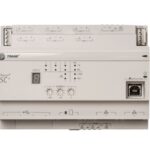
Figure 1. Symbio 800 rotary address and service tool port

Service Tool for Symbio™ 800 Configuration
The service tool used to modify the Symbio™ 800 controller is a standard web browser. The Symbio 800 webpage is accessed by using a standard USB type A/B cable. Connect the USB cable between a laptop and the service tool port on the Symbio 800 controller (shown in Figure 1, p. 6).
Connecting to the Symbio™ 800 Web Interface
- Connect a laptop to the Symbio™ 800 controller using a USB cable.
- On the laptop, open a web browser to http://198.80.18.1/
- When the Symbio 800 page displays, click Log In.
Figure 2. Symbio 800 log in screen

Note: The Symbio 800 web interface can only be viewed using the USB connection. Ethernet port 1 and Ethernet port 2 will not allow access to the Symbio web server to meet IT security requirements.
Protocol Configuration
To access the Symbio™ 800 Protocol Configuration page:
- Connect to the Symbio 800 web interface.
- On the left-hand navigation, click Installation.
- Click Identification and Communications.
Figure 3. Identification and Communications

- Click the Protocol Configuration tab.
Figure 4. Protocol Configuration

- View the existing Protocol Configuration settings.
Note: There are no LonTalk® communication parameters to edit.
LonTalk® Protocol Settings
The Symbio™ 800 controller supports LonTalk® communications with the optional LonTalk module. The LonTalk module is din rail mounted and is connected to the Symbio 800 controller using USB.
Note: The Symbio 800 rotary addresses are not used with LonTalk communications.
Figure 5. LonTalk protocol configuration

- Verify the LonTalk adapter connection status is Connected. If the adapter connection status is another state, verify the LonTalk adapter is connected to a Symbio 800 USB port.
- Verify the Link Status is Online. If the Link Status is set to a different state, LonTalk network management software such as Trane Rover software is needed to set the Link status to Online.
- The Service Pin button will send a service pin message to the LonTalk network. A service pin will broadcast the Neuron ID to the LonTalk network so a LonTalk network management tool can find a device and set its Domain, Subnet, Node address.
LonTalk communication wire is connected to the LonTalk adapter. LonTalk does not require wire polarity but it is recommended that wire polarity be observed. Refer to the LonTalk standard for detailed information on LonTalk wiring.
All LonTalk devices must have a unique DSN address and must have the same Domain value. The Symbio 800 LonTalk adapter ships on the zero-length domain so it can be easily discovered by LonTalk network managers and tools.
Profile Definition and Network Variables
Download
Equipment-specific LonTalk® points lists are available on the trane.com product page.
The tables are sorted as follows:
- Tables are listed by unit/profile type and sorted by netwrok variable number.
- Tables are sorted by name and provide a complete list of names, types, values/ranges, and descriptions.
Note: Not all points are available to the user. The available data points are defined during selfconfiguration and are dependent on the type of equipment.
Appendix A. Arbitration
The Symbio™ 800 controller includes arbitration logic for several points. For each read/write point designated as “BAS”, an associated “Arbitration” point determines the behavior of that communicated data compared to the local hardwired (or wireless) sensor and a default value.
As shown in Figure 6, p. A–1, the arbitrator considers all possible sources of the provided data, including Building Management Systems (BMS), local, and default. Each potential source is defined at a pre-determined, fixed priority. When the arbitration method is selected as full/auto, the BMS value is used instead of the local or default values.
The point designator with the arbitrator suffix includes the full priority array, allowing the user to see the value associated with all potential sources considered in the logic. The active point reflects the result of the arbitration logic.
Because the arbitrated points are normally associated with sensors, the default value is invalid, meaning the value must be provided either by the BMS or the local sensor.
Figure 6. Arbitration method – full/auto

When the Arbitration Method is selected as local, the BMS value is ignored and local value is used instead. Though the arbitration logic still considers all inputs, any values sent by the BMS are effectively ignored.
Figure 7. Arbitration method – local

Appendix B. Symbio™ 800 Controller Layout
Figure 8. Symbio 800 controller display and LEDs
7–Segment status display
Table 1. Codes for 7–segment display segment
| Code | Description |
| U0. | Waiting for USB drives to mount |
| U2. | Checking signature on the .scfw file |
| U3. | Checking software maintenance plan |
| U4. | Reformatting main filesystem (clearing database) |
| U5. | Beginning update |
| U12. | Searching for .scfw files on USB drive(s) |
| U51. | Updating main firmware |
| U54. | Updating FPGA image |
| U55. | Updating U-boot image |
| U57. | Updating recovery partition |
Note: A code starting with an “F” indicates a failure, and requires Trane Service to resolve the issue.
P1 Link — BACnet® MS/TP or Modbus® RTU
- RS-485 daisy chain
- Used for connection to a manager controller
Figure 9. P2 Modbus device (factory installed Modbus server devices)
Note: The P2 link is intended for factory devices only and should not have any other devices added this link.

Figure 10. P3 machine bus (global bus — internal communication bus)
Note: The P3 link is intended for factory devices only and should not have any other devices added this link.

Figure 11. IMC link terminations for optional Air-Fi® and expansion module (XM30)


For more information on Expansion Module wiring reference BAS-SVX46* – Expansion Module Installation Operation and Maintenance Manual.
Figure 12. (4) USB connectors

The controller automatically detects devices on any of the ports (not port specific). The controller ships with all ports enabled, but they can be disabled via the Web interface.
Note: The USB ports are not to be used for any devices that are not Trane approved, such as cellular phones.
Figure 13. Ethernet port 2

Note: Ethernet Port 2 is for use with the Touch Screen display only. Communication to other devices is not supported.
Trane – by Trane Technologies (NYSE: TT), a global innovator – creates comfortable, energy efficient indoor environments for commercial and residential applications. For more information, please visit trane.com or tranetechnologies.com.
Trane has a policy of continuous product and product data improvements and reserves the right to change design and specifications without notice. We are committed to using environmentally conscious print practices.
BAS-SVP084A-EN 30 Aug 2024
Supersedes (New)

Documents / Resources
 |
TRANE TM 800 Lon Talk Integration [pdf] Installation Guide TM 800 Lon Talk Integration, TM 800, on Talk Integration, Talk Integration, Integration |