![]() OPERATING INSTRUCTIONS
OPERATING INSTRUCTIONS
DIGITAL SPEAKER PROCESSOR DP-SP3
DP-SP3 Digital Speaker Processor
Thank you for purchasing TOA’s Digital Speaker Processor.
Please carefully follow the instructions in this manual to ensure long, trouble-free use of your equipment.
IMPORTANT SAFETY INSTRUCTIONS
- Read these instructions.
- Keep these instructions.
- Heed all warnings.
- Follow all instructions.
- Do not use this apparatus near water.
- Clean only with dry cloth.
- Do not block any ventilation openings. Install in accordance with the manufacture’s instructions.
- Do not install near any heat sources such as radiators, heat registers, stoves, or other apparatus (including amplifiers) that produce heat.
- Do not defeat the safety purpose of the polarized or grounding-type plug.
A polarized plug has two blades with one wider than the other. A grounding type plug has two blades and a third grounding prong. The wide blade or the third prong are provided for your safety.
If the provided plug does not fit into your outlet, consult an electrician for replacement of the obsolete outlet. - Protect the power cord from being walked on or pinched particularly at plugs, convenience receptacles, and the point where they exit from the apparatus.
- Only use attachments/accessories specified by the manufacturer.
- Use only with the cart, stand, tripod, bracket, or table specified by the manufacturer, or sold with the apparatus. When a cart is used, use caution when moving the cart/ apparatus combination to avoid injury from tip-over.

- Unplug this apparatus during lightning storms or when unused for long periods of time.
- Refer all servicing to qualified service personnel. Servicing is required when the apparatus has been damaged in any way, such as power-supply cord or plug is damaged, liquid has been spilled or objects have fallen into the apparatus, the apparatus has been exposed to rain or moisture, does not operate normally, or has been dropped.
SAFETY PRECAUTIONS
- Before installation or use, be sure to carefully read all the instructions in this section for correct and safe operation.
- Be sure to follow all the precautionary instructions in this section, which contain important warnings and/or cautions regarding safety.
- After reading, keep this manual handy for future reference.
Safety Symbol and Message Conventions
Safety symbols and messages described below are used in this manual to prevent bodily injury and property damage which could result from mishandling. Before operating your product, read this manual first and understand the safety symbols and messages so you are thoroughly aware of the potential safety hazards.
![]() WARNING
WARNING
Indicates a potentially hazardous situation which, if mishandled, could result in death or serious personal injury.
![]() CAUTION
CAUTION
Indicates a potentially hazardous situation which, if mishandled, could result in moderate or minor personal injury, and/or property damage.
![]() WARNING
WARNING
When Installing the Unit
- Do not expose the unit to rain or an environment where it may be splashed by water or other liquids, as doing so may result in fire or electric shock.
- Use the unit only with the voltage specified on the unit. Using a voltage higher than that which is specified may result in fire or electric shock.
- Do not cut, kink, otherwise damage nor modify the power supply cord. In addition, avoid using the power cord in close proximity to heaters, and never place heavy objects — including the unit itself — on the power cord, as doing so may result in fire or electric shock.
- Avoid installing or mounting the unit in unstable locations, such as on a rickety table or a slanted surface. Doing so may result in the unit falling down and causing personal injury and/or property damage.
- Since the unit is designed for indoor use, do not install it outdoors. If installed outdoors, the aging of parts causes the unit to fall off, resulting in personal injury. Also, when it gets wet with rain, there is a danger of electric shock.
When the Unit is in Use
- Should the following irregularity be found during use, immediately switch off the power, disconnect the power supply plug from the AC outlet and contact your nearest TOA dealer. Make no further attempt to operate the unit in this condition as this may cause fire or electric shock.
- If you detect smoke or a strange smell coming from the unit.
- If water or any metallic object gets into the unit
- If the unit falls, or the unit case breaks
- If the power supply cord is damaged (exposure of the core, disconnection, etc.)
- If it is malfunctioning (no tone sounds.)
- To prevent a fire or electric shock, never open nor remove the unit case as there are high voltage components inside the unit. Refer all servicing to qualified service personnel.
- Do not place cups, bowls, or other containers of liquid or metallic objects on top of the unit. If they accidentally spill into the unit, this may cause a fire or electric shock.
- Do not insert nor drop metallic objects or flammable materials in the ventilation slots of the unit’s cover as this may result in fire or electric shock.
- The apparatus shall be connected to a main socket outlet with a protective earthing connection.
- The socket-outlet shall be installed near the equipment and the plug shall be easily accessible.
CAUTION
When Installing the Unit
- Never plug in nor remove the power supply plug with wet hands, as doing so may cause electric shock.
- When unplugging the power supply cord, be sure to grasp the power supply plug; never pull on the cord itself. Operating the unit with a damaged power supply cord may cause a fire or electric shock.
- When moving the unit, be sure to remove its power supply cord from the wall outlet. Moving the unit with the power cord connected to the outlet may cause damage to the power cord, resulting in fire or electric shock. When removing the power cord, be sure to hold its plug to pull.
- Do not block the vents on the unit’s front and rear panels. Doing so may cause heat to build up inside the unit and result in fire. Also, periodically clean the ventilation slots of dust.
- Avoid installing the unit in humid or dusty locations, in locations exposed to the direct sunlight, near the heaters, or in locations generating sooty smoke or steam as doing otherwise may result in fire or electric shock.
- Be sure to follow the instructions below when rackmounting the unit. Failure to do so may cause a fire or personal injury.
- Install the equipment rack on a stable, hard floor. Fix it with anchor bolts or take other arrangements to prevent it from falling down.
- When connecting the unit’s power cord to an AC outlet, use the AC outlet with current capacity allowable to the unit.
(Every version except the DP-SP3 CU for US)
· The supplied rack-mounting screws can be used for the TOA equipment rack only. Do not use them for other racks.
(DP-SP3 CU for US)
· Rack-mounting screws are not supplied with the unit. Prepare them that are appropriate for the equipment rack.
· Be sure to complete installation and cable connections before connecting the unit’s power plug to the power source. When uninstalling the unit or disconnecting the unit’s cables, be sure to disconnect the power plug from the power source first. Doing otherwise may result in electric shock.
- LAN Connector cannot connect to Connector which might catch overvoltage.
When the Unit is in Use
- If dust accumulates on the power supply plug or in the wall AC outlet, a fire may result. Clean it periodically. In addition, insert the plug in the wall outlet securely.
- Switch off the power, and unplug the power supply plug from the AC outlet for safety purposes when cleaning or leaving the unit unused for 10 days or more. Doing otherwise may cause a fire or electric shock.
![]() The lighting flash with arrowhead symbol, within an equilateral triangle, is intended to alert the user to the presence of uninsulated “dangerous voltage” within the product’s enclosure that may be of sufficient magnitude to constitute a risk of electric shock to persons.
The lighting flash with arrowhead symbol, within an equilateral triangle, is intended to alert the user to the presence of uninsulated “dangerous voltage” within the product’s enclosure that may be of sufficient magnitude to constitute a risk of electric shock to persons.
![]() The exclamation point within an equilateral triangle is intended to alert the user to the presence of important operation and maintenance (servicing) instruction in the literature accompanying the appliance.
The exclamation point within an equilateral triangle is intended to alert the user to the presence of important operation and maintenance (servicing) instruction in the literature accompanying the appliance.
GENERAL DESCRIPTION
The DP-SP3 is a digital speaker processor equipped with signal processing functions such as Equalizer, Crossover, Matrix, Compressor, and Delay.
When connected to a LAN, settings and operations of the DP-SP3 can be performed on a PC with the DP-SP3 PC Software*¹ installed.
It can be mounted in a 19″ EIA component rack (1U size*²).
* Can be downloaded from the TOA DATA Library ( https://www.toa-products.com/international/ ).
*2 1U size = 44.5 mm (standard size)
FEATURES
- Digital processor with 2 input channels and 6 output channels
- Equipped with an EQ characteristic library for the TOA speakers
- Equipped with various signal processing functions: Equalizer, Crossover, Matrix, Compressor, Delay, Mute, and Gain
- Input sensitivity switchable since the analog circuit has an Input PAD.
- Built-in analog output attenuator permits the system gain to be adjusted suitably for the input sensitivity of the amplifier to be connected.
- Level display of all inputs and outputs
- 16 patterns of setting parameters storable within the DP-SP3 unit as Preset memories (Preset memory functi on)
- Use of contact input terminals enables preset memory recall, volume control of output channels, and Mute ON/OFF.
HANDLING PRECAUTIONS
- The socket-outlet shall be installed near the equipment and the plug shall be easily accessible.
- The supplied power supply cord is designed for exclusive use with this unit. Never use it with other equipment.
- Install the unit in locations where the temperature is between 0 and +40 °C (32 and 104 °F) and the moisture is less than 90% (no dew condensation must be formed).
- The DP-SP3 is a precision audio component. To prevent failure, avoid locations where the unit may be exposed to strong shocks or vibrations.
- To clean, be sure to first switch off the unit’s power, then wipe with a dry cloth. When the unit gets very dirty, use a cloth damped in a neutral cleanser. Never use benzene, thinner, alcohol, or chemically-treated cleaning cloth because such volatile liquids could deform or discolor the unit.
NOMENCLATURE AND FUNCTIONS
[Front]
- Power switch [POWER ON, OFF]
Power is switched on and off with each depression of this switch. - Power indicator [POWER]
Lights when the power is switched on. - Intake vent
Lets in the air from the front and forcibly exhausts it from the rear. - Operation status indicators [STATUS]
• RUN indicator [RUN] Indicates the DP-SP3’s operation status.
Lights green: Normal operation
Flashes green: Mute switches in lock mode
Flashes orange: Fan failure
Flashes red: DSP operation failure
Unlit: CPU failure
• LINK indicator [LINK] Indicates the connection status with the DP-SP3 PC Software.
Lights green: Preset memory recall being interlocked.
Flashes green: Communicating with PC or external device.
Unlit: No connection is established. - Preset indicators [PRESET]
The indicator of the Preset No. currently being selected lights. - Input level indicators [INPUTS]
Indicate the audio input levels.
Note that the input level is too high when the PEAK indicator always lights. - Output level indicators [OUTPUTS]
Indicate the audio output levels.
Note that the output level is too high when the PEAK indicator always lights.
Adjust the DP-SP3 unit’s volume level by the PC with the DP-SP3 PC Software installed. - Mute switches [MUTE, 1 through 6]
Pressing the Mute switch causes the corresponding channel’s output to be muted and the “−40” level LED of the Output level indicators (7) flashes orange. Pressing it again cancels mute, and the indicator goes off.
All mute switches can be placed in lock mode using the DP-SP3 PC software. Pressing any mute switch in lock mode causes the RUN indicator (4) to flash green.
[Rear]
-
AC power input terminalConnect this terminal to an AC power source with the supplied dedicated AC power cord.
-
Functional ground terminalHum noise may be generated when external equipment is connected to the unit. Connecting this terminal to the functional ground terminal of the external equipment may reduce the hum noise.Note: This ground is not for protective ground.
-
Exhaust ventForcibly exhausts the air let in from the front.
-
Outputterminals[OUTPUTS+4dBu,1−6]
+4 dB*, 600 Ω, balanced, removable terminal block -
Inputterminals[INPUTS+4dBu,1−2]+4 dB*, 600 Ω, balanced, removable terminal block
-
Contact input terminals[CONTACTINPUTS1−4,C]Removable terminal block, 4-channel contact input terminal
*0 dB = 0.775 V
Following controls can be performed using these terminals.
• Preset memory recall
• Mute ON/OFF
• Volume control (UP/DOWN)
For the control method, see p. 14, “CONTROL METHOD USING THE CONTACT INPUT TERMINALS.”
Tip
Use the DP-SP3 PC Software to assign control functions to the terminals. -
LAN port
Connect this port to the LAN-connected switching hub with a LAN cable.
• LINK indicator
Lights when the link is established and during data transmission or reception.
• FULL indicator
Lights during Full duplex operation.
The DP-SP3’s default IP address is “192.168.14.1”.
Use the DP-SP3 PC Software to perform IP address setting.
SYSTEM CONFIGURATION EXAMPLE
7.1. Control by the External Control Device
The following 2 methods are used to control the DP-SP3 from the external control device.
Functions to be controlled differ depending on each method.
7.1.1. Method of direct control
This example shows a method to control the DP-SP3 by directly connecting the external device’s contact outputs to the DP-SP3 unit’s contact inputs.
Controllable functions: Preset memory recall, Volume control, and Mute ON/OFF [Controlling a single DP-SP3] [Controlling multiple DP-SP3 units (up to 4 units)]
In this event, control becomes active only to the DP-SP3 to which the contact output is connected. But the Preset memory recall function is interlocked among the DP-SP3 units.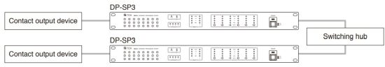 7.1.2. Method of control via LAN
This example shows a method to control the DP-SP3 by the external control devices via LAN.
External control ![]() DP-SP3: Preset memory recall, Volume control, Matrix settings, and Mute ON/OFF
DP-SP3: Preset memory recall, Volume control, Matrix settings, and Mute ON/OFF
DP-SP3 ![]() External control: Preset memory number, Volume control, Matrix, and Channel mute notification
External control: Preset memory number, Volume control, Matrix, and Channel mute notification
[Controlling a single DP-SP3] [Controlling multiple DP-SP3 units (up to 4 units)]
In this event, control becomes active only to the control target DP-SP3. But the Preset memory recall function is interlocked among the DP-SP3 units.
Other controllable functions are the same as described above. 7.2. Control by the M-864D Digital Mixer
The M-864D can control up to 4 DP-SP3 units.
[Controlling a single DP-SP3]
M-864D ![]() DP-SP3: Preset memory recall
DP-SP3: Preset memory recall
DP-SP3 ![]() M-864D: Preset memory number change request
M-864D: Preset memory number change request [Controlling multiple DP-SP3 units (up to 4 units)]
M-864D ![]() DP-SP3: Preset memory recall
DP-SP3: Preset memory recall
DP-SP3 ![]() M-864D: Preset memory number change request
M-864D: Preset memory number change request 7.3. Control by a PC
A single PC can control up to 4 DP-SP3 units.
[Controlling a single DP-SP3]
PC ![]() DP-SP3: Preset memory recall/save, Online edit, and Mute ON/OFF
DP-SP3: Preset memory recall/save, Online edit, and Mute ON/OFF
DP-SP3 ![]() PC: Preset memory number change request and Volume level display
PC: Preset memory number change request and Volume level display [Controlling multiple DP-SP3 units (up to 4 units)]
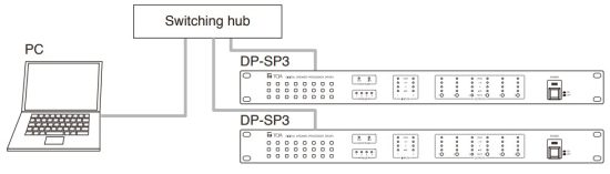 [Controlling 5 or more DP-SP3 units]
It is possible to control DP-SP3 units by activating multiple DP-SP3 PC Software programs. 7.4. Control by Various Types of Devices
This example shows a method to control multiple DP-SP3 units (up to 4 units) by a PC, the contact output devices, the external control devices, and the M-864D.
MUTE FUNCTION OPERATION
The DP-SP3 can perform Mute function operation.
Use this function when wishing to mute each output.
Use the DP-SP3 unit or the DP-SP3 PC Software to perform mute operation.
The DP-SP3 can perform each individual output mute, while the DP-SP3 PC Software can perform both each individual output mute and simultaneous mute of all outputs (Mute All).
For the operations of the DP-SP3 PC Software, read the separate DP-SP3 Software Instructions*.
* Can be downloaded from the TOA DATA Library ( https://www.toa-products.com/international/ ).
8.1. Mute Indicators
For the output channel on which the mute function is operating, the “−40” level indicator of the corresponding output channel lights orange, flashes* 1 , or flashes intermittently* 2.

There is a priority order for the mute operating indications between the operation performed from the DPSP3 and that performed using the DP-SP3 PC Software. If multiple mute operations overlap, then the mute operating indication with the higher priority is activated.
[Indication priority level of mute operation and indicator status]
Priority level
High
↓
Low
- Mute All using the DP-SP3 PC Software :
- Mute and Contact control mute by the DP-SP3 :
- An individual mute using the DP-SP3 PC Software and External control mute :
Intermittently flashes (Flashes twice, then repeats.)
Flashes
Lights
8.2. Turning on the Mute Function by the DP-SP3
Step 1. Confirm that the “−40” level indicator of the output channel to be muted remains unlit.
Note
When an output channel’s indicator lights or intermittently flashes, this indicates that the output channel is being muted by the DP-SP3 PC Software. Step 2. Press the Mute switch of the corresponding channel, then release it when the “−40” output level indicator of that channel begins to flash.
[Indicator status when the Mute operations overlap]
Example: When Mute is activated by the DP-SP3 followed by Mute All activation using the DP-SP3 PC Software.  8.3. Turning OFF the Mute Function by the DP-SP3
Step 1. Confirm that the “−40” level indicator of the output channel wishing to cancel the mute operation is flashing.
Note
Mute operation of the output channel, of which level indicator is intermittently flashing or lighting, cannot be cancelled by the DP-SP3.
Step 2. Press the Mute switch of the corresponding channel, then release it when the “−40” level indicator of that channel stops flashing, then goes out or lights*. * The indicator lights if the mute operation with lower priority indication activated by the DP-SP3 PC Software overlap with the muting operated by the DP-SP3. Use the DP-SP3 PC Software to cancel the mute.
PRESET NUMBER INDICATION FUNCTION
Using the DP-SP3 PC Software, various setting data can be stored on the DP-SP3, which can be recalled.
The saved setting data is referred to as “Preset memory.”
The DP-SP3 PC Software allows up to 16 patterns of the Preset memories to be stored or recalled.
For the store and recall methods, read the separate DP-SP3 Software Instructions.
While one of the Preset memories 1 through 4 is being recalled, its corresponding numbered Preset indicator of the DP-SP3 lights. Tip
Tip
When all 4 Preset indicators are unlit, the DP-SP3 is placed in one of the following statuses.
- Preset memories 5 through 16 are being recalled.
- The DP-SP3 is activating in Resume function ON state.
- Setting is changed after activating the DP-SP3.
CONTROL METHOD USING THE CONTACT INPUT TERMINALS
This chapter will describe control method of the contact input terminals to recall the Preset memory, adjust the
volume level of output channels, and control the Mute ON/OFF by external equipment.
Note: For the settings of each individual function, read the separate DP-SP3 Software Instructions.
10.1. Preset Memory Recall
Up to 4 Preset memories in Direct mode and up to 16 Preset memories in Binary mode can be controlled.
[Direct mode]
Either (A) or (B) below can be used for the control method.
In either case, Preset memory switches 250 ms or more after the contact inputs have been closed.
(A) Maintaining the contact terminal closed aftethe Preset memory has been switched. (B) Opening the contact terminal after the Preset memory has been switched.
 Tip
Tip
Use the DP-SP3 PC Software to assign which terminals 1 through 4 to which Preset memory.
Read the separate DP-SP3 Software instructions.
[Binary mode]
The following tables show the relationship between the statuses to be given to the terminals and Preset memories to be recalled.
Selecting 2 Preset memories using the terminal 4
| Preset memory number | Terminal 4 |
| 1 | Open |
| 2 | Closed |
Selecting 4 Preset memories using the terminals 3 and 4
| Preset memory number | Terminal 3 | Terminal 4 |
| 1 | Open | Open |
| 2 | Open | Closed |
| 3 | Closed | Open |
| 4 | Closed | Closed |
Selecting 8 Preset memories using the terminals 2, 3, and 4
| Preset memory number | Terminal 2 | Terminal 3 | Terminal 4 |
| 1 | Open | Open | Open |
| 2 | Open | Open | Closed |
| 3 | Open | Closed | Open |
| 4 | Open | Closed | Closed |
| 5 | Closed | Open | Open |
| 6 | Closed | Open | Closed |
| 7 | Closed | Closed | Open |
| 8 | Closed | Closed | Closed |
Selecting 16 Preset memories using the terminals 1, 2, 3, and 4
| Preset memory number | Terminal 1 | Terminal 2 | Terminal 3 | Terminal 4 |
| 1 | Open | Open | Open | Open |
| 2 | Open | Open | Open | Closed |
| 3 | Open | Open | Closed | Open |
| 4 | Open | Open | Closed | Closed |
| 5 | Open | Closed | Open | Open |
| 6 | Open | Closed | Open | Closed |
| 7 | Open | Closed | Closed | Open |
| 8 | Open | Closed | Closed | Closed |
| 9 | Closed | Open | Open | Open |
| 10 | Closed | Open | Open | Closed |
| 11 | Closed | Open | Closed | Open |
| 12 | Closed | Open | Closed | Closed |
| 13 | Closed | Closed | Open | Open |
| 14 | Closed | Closed | Open | Closed |
| 15 | Closed | Closed | Closed | Open |
| 16 | Closed | Closed | Closed | Closed |
Note: Binary control example by way of the 3P terminal
 To switch the Preset memory, maintain the given state for 250 ms or more after placing each terminal in the state corresponding to the Preset memory to be recalled.
Maintain the terminal state as it is until changing the Preset memory next time.
10.2. Output Volume Control
- Closing the terminals for 250 ms or more causes an action to operate by 1 step*.
 * Select the variation from “1 dB step,” “3 dB step,” or “6 dB step” using the DP-SP3 PC Software.
 - Maintaining the terminals closed for 250 ms or more causes a 1-step action to repeat every 800 ms for 3 times, followed by 1-step action repeating every 200 ms. Opening the terminals stops these continuous actions.

Tip
Use the DP-SP3 PC Software to assign the function to terminals.
Read the separate DP-SP3 Software instructions.
10.3. Output Mute
There are 2 control methods to mute output: Closed control and Pulse control.
Use the DP-SP3 PC Software to select control method.
[Closed control]
Closing the terminals for 250 ms or more causes Mute to turn ON.
While, opening the terminals for 250 ms or more causes Mute to turn OFF. [Pulse control]
Closing the terminals for 250 ms or more causes Mute to turn ON.
Mute turns OFF 250 ms or more after opening once and closing again the terminals.
Mute switches between ON and OFF each time open and closed states are alternately repeated.
FIRMWARE VERSION INDICATION
The DP-SP3’s firmware version can be confirmed by checking the lighting indicator status on the DP-SP3’s front panel.
- Firmware Version Indication
The DP-SP3’s firmware version is expressed as shown in the following example.
Here, the individual numbers are denoted by A, B, and C.
(Example)
- How to check firmware version
When the DP-SP3 is activated, the indicators on the front panel light for 3 seconds, indicating the figure of “A,”
“B,” and “C.”
The figure that each indicator indicates is as follows.
Note: If all the indicators in “B” and “C” sections are unlit, it represents “0.”
 In the above example of “Ver. 1.2.4”, the indicators of each section light as follows.
INITIALIZING THE DP-SP3
 Step 1.Turn off the power switch.
Step 2. Turn on the power switch while continuously holding down the Mute switches 1, 2, and 5.
All the front panel-mounted indicators light, then those except Input and Output level indicators go off.
Step 3. When only the Input and Output level indicators light, release the Mute switches, then these indicators turn into flashing.
Step 4. While the Input and Output level indicators are flashing, press the Mute switch 3 three times.
All the front panel-mounted indicators go off, and the initialization process starts.
The DP-SP3 restarts after initialization is complete.
INSTALLATION
13.1. Installation Precautions
Be sure to leave the installation work (rack mounting) to a qualified installer.
![]() CAUTION
CAUTION
When installing the unit in an equipment rack, do not block the ventilation slots on the unit’s both sides and rear side. Doing so may cause heat to build up inside the unit and result in fire.
- Elevated Operating Ambient – If installed in a closed or multi-unit rack assembly, the operating ambient temperature of the rack environment may be greater than room ambient. Therefore, consideration should be given to installing the equipment in an environment compatible with the maximum ambient temperature (Tma) specified by the manufacturer.
- Reduced Air Flow – Installation of the equipment in a rack should be such that the amount of air flow required for safe operation of the equipment is not compromised.
- Mechanical Loading – Mounting of the equipment in the rack should be such that a hazardous condition is not achieved due to uneven mechanical loading.
- Circuit Overloading – Consideration should be given to the connection of the equipment to the supply circuit and the effect that overloading of the circuits might have on overcurrent protection and supply wiring.
Appropriate consideration of equipment nameplate ratings should be used when addressing this concern. - Reliable Earthing – Reliable earthing of rack-mounted equipment should be maintained. Particular attention should be given to supply connections other than direct connections to the branch circuit (e.g. use of power strips).”
13.2. Mounting in a Rack
CAUTION
(When rack mounting screws are supplied)
The supplied rack-mounting screws can be used for the TOA equipment rack only. Do not use them for other racks.
When installing the unit in a rack other than that of TOA, be sure to use the screws with a diameter of over 5 mm (0.2”) and length of over 12 mm (0.47”) to mount the unit.
Failure to do so may cause the unit to fall, resulting in personal injury.
(When rack mounting screws are not supplied)
Rack mounting screws are not supplied with the unit.
Be sure to use the screws with a diameter of over 5 mm (0.2”) and length of over 12 mm (0.47”) to mount the unit.
Failure to do so may cause the unit to fall, resulting in personal injury.
CONNECTION
14.1. Connection Example 14.2. Removable Terminal Plug Connection
Notes
- Avoid soldering stranded or shielded cable, as contact resistance may increase when the cable is tightened and the solder is crushed, possibly resulting in an excessive rise in joint temperatures.
- When connecting 2 cables or a shielded cable to a single terminal, use a ferrule terminal with an insulation sleeve to crimp the cables because such cable conductors could become loose.
Recommended ferrule terminals for signal cables
(made by Phoenix Contact)
Unit: mm (in)
| Model Number | a | b | l1 | l2 | |
| 1 | AI 0,34-8 TQ | 2 (0.08) | 0.8 (0.03) | 12.5 (0.49) | 8 (0.31) |
| 2 | AI 0,5-8 WH | 2.5 (0.1) | 1.1 (0.04) | 14 (0.55) | 8 (0.31) |

| Model Number | a | a1 | a2 | b | l1 | l2 | |
| 3 | AI 1,5-8 BK | 3.4 (0.31) | 1.8 (0.07) | 14 (0.55) | 8 (0.31) | ||
| 4 | AI-TWIN 2x 1,5-8 BK | 6.6 (0.26) | 3.6 (0.14) | 2.3 (0.09) | 16 (0.63) | 8 (0.31) |
Crimping tool: CRIMPFOX UD6-4 (made by Phoenix Contact)
Cable sheath to trim * Expose 8 mm (0.31’’) or more when using the above ferrule terminal, and cut off an extra conductor protruding from the sleeve.
Wiring procedures
Step 1. Wiring the supplied removable terminal plug.
1-1. Loosen the terminal screws to insert the wire.
1-2. Tighten the terminal screws.
Ensure that the wire does not break free when pulled. If the wire does pull free, repeat the connection procedure from the start.
Step 2. Insert the wired terminal plug into the corresponding terminal block in the unit’s rear panel.
Note
Do not reverse Steps 1 and 2 above. Force is applied to the connected receptacle pins while tightening the terminal screw and they may be damaged, resulting in bad connector contact.  Recommended type of screwdriver with the following blade width:
For 5P terminal plug: About 2.5mm (0.1”) wide blade
For 3P terminal plug: About 3.5mm (0.14”) wide blade
BLOCK DIAGRAM

SPECIFICATIONS
| Version | CE/CE-GB | CE-AU | CU |
| Power Source | 220−240 V AC, 50/60 Hz | 220−240 V AC, 50 Hz | 100−120 V AC, 60 Hz |
| Power Consumption | 25 W | ||
| Frequency Response | 20 Hz − 20 kHz, ±1 dB | ||
| Sampling Frequency | 96 kHz | ||
| Dynamic Range | 110 dB or more | ||
| Distortion | 0.03 % or less, 1 kHz, +4 dB* input/output, 20 Hz − 20 kHz BPF | ||
| Crosstalk | −80 dB or less, 1 kHz | ||
| Input | 2 channels, +4 dB* (max. +24 dB*), 10 kΩ, electronically-balanced, removable terminal block (3P) | ||
| Output | 6 channels, +4 dB* (max. +24 dB*), applicable load 600 Ω or more, electronically-balanced, removable terminal block (3P) | ||
| AD Converter | 24 bits | ||
| DA Converter | 24 bits |
| Preset Memory | 16 |
| Signal Processing Section | |
| Equalizer/Filter | Parametric equalizer: 20 Hz − 20 kHz, ±15 dB, Q: 0.267 − 69.249 Filter:
High-pass filter: 20 Hz − 20 kHz, 6 dB/oct, 12 dB/oct |
| Crossover | 2 ways, 3 ways, 4 ways Crossover filter: 20 Hz − 20 kHz, 6 dB/oct, 12 dB/oct, 18 dB/oct, 24 dB/oct, −15 to +12 dB, polarity switchable Delay: 0 − 170.656 ms in 0.01 ms steps |
| Compressor | Threshold: −20 to +20 dB* in 1 dB steps Ratio: 1:1, 1.1:1, 1.2:1, 1.3:1, 1.5:1, 1.7:1, 2:1, 2.3:1, 2.6:1,3:1, 4:1, 7:1, 8:1,10:1, 12:1, 20:1, ∞:1 Attack time: 0.2 ms − 5 s Release time: 10 ms − 5 s |
| Delay | Delay time: 0 − 682.656 ms in 0.01 ms steps |
| Matrix | 2 x 6 |
| Crosspoint Gain | – ∞ to 0 dB in 1 dB steps |
| Function | Input PAD (−16 dB) control, analog output attenuator (− ∞ to 0 dB in 1 dB steps) control, EQ characteristic library for TOA speakers, input/output level indicator (4-point LED indicator), output MUTE switch x 6 |
| Control | |
| Contact input | 4 channels, open voltage: 5 V DC, short-circuit current: 5 mA, removable terminal block (5 P) Control function: preset memory selection, volume control, and mute |
| Network | Network I/F: 1 channel of 10BASE-T/100BASE (auto-negotiation), RJ45 connector, connection via switching hub Network protocol: TCP/IP Connection cable: Shielded Cat. 5 or higher twisted pair cable for LAN (Cat. 5-STP or better) Maximum cable length: 100 m (109.36 yd) (between DP-SP3 and switching hub) |
| Operating Temperature | 0 to 40 ºC (32 to 104 ºF) |
| Operating Humidity | 90 %RH (no condensation) |
| Finish | Panel: Aluminum, hairline, black, Case: Surface−treated steel plate |
| Dimensions | 482 (w) x 44 (h) x 288.7 (d) mm (18.98” x 1.73” x 11.37”) |
| Weight | 3.1 kg (6.83 lb) |
* 0 dB = 0.775 V
Note: The design and specifications are subject to change without notice for improvement.
• Accessories
[CE/CE-AU/CE-GB version]
Power supply cord (2 m or 6.56 ft) ………………………. 1
Removable terminal plug (3 P) ……………………………. 8
Removable terminal plug (5 P) ……………………………. 1
Rack mounting screw ………………………………………… 4
[CU version]
Power supply cord (2 m or 6.56 ft) ………………………. 1
Removable terminal plug (3 P) ……………………………. 8
Removable terminal plug (5 P) ……………………………. 1
DIMENSIONAL DIAGRAM
 FCC REQUIREMENTS
Note
This equipment has been tested and found to comply with the limits for a Class A digital device, pursuant to Part 15 of the FCC Rules. These limits are designed to provide reasonable protection against harmful interference when the equipment is operated in a commercial environment. This equipment generates, uses, and can radiate radio frequency energy and, if not installed and used in accordance with the instruction manual, may cause harmful interference to radio communications.
Operation of this equipment in a residential area is likely to cause harmful interference in which case the user will be required to correct the interference at his own expense.
Modifications
Any modifications made to this device that are not approved by TOA Corporation may void the authority granted to the user by the FCC to operate this equipment.
This Class A digital apparatus complies with Canadian ICES-003.
Warning
This equipment is compliant with Class A of CISPR 32. In a residential environment this equipment may cause radio interference.
![]() https://www.toa-global.com/en
https://www.toa-global.com/en
133-02-00049-03
Documents / Resources
 |
TOA DP-SP3 Digital Speaker Processor [pdf] Instruction Manual DP-SP3, DP-SP3 Digital Speaker Processor, DP-SP3, Digital Speaker Processor, Speaker Processor, Processor |