THORLABS QG4X-AG Galvo Scan Head and Controller User Guide

Chapter 1 Introduction
Intended Use
his manual covers the installation and use of Thorlabs’ QG4 & QG5 VantagePro® Series 1-Axis Galvanometer Scanners. These scanners are designed to deflect a laser beam from its original trajectory and steer the beam through a specified path. Each galvanometer (galvo) motor should only be used with its paired Class 1 servo amplifier, which is included with the system. To control the galvo motor, a user-provided command generator is required to supply analog voltage commands within the specified range. Refer to the Class 1 servo amplifier manual for details. A QSM4 galvanometer mount (sold separately), or a custom mount that meets the recommended parameters, can be used to mount the motor onto an optical table. The mount, power supply, and command generator are not included.
The product may only be used in accordance with the instructions described in this manual. Any other use will invalidate the warranty.
Explanation of Safety Warnings
![]() Danger indicates a hazard with a high level of risk that, if not avoided, will result in death or serious injury.
Danger indicates a hazard with a high level of risk that, if not avoided, will result in death or serious injury.
![]() Warning indicates a hazard with a medium level of risk that, if not avoided, could result in death or serious injury.
Warning indicates a hazard with a medium level of risk that, if not avoided, could result in death or serious injury.
![]() Caution indicates a hazard with a low level of risk that, if not avoided, could result in minor or moderate injury.
Caution indicates a hazard with a low level of risk that, if not avoided, could result in minor or moderate injury.
![]() Indicates information considered important, but not hazard-related, such as possible damage to the product.
Indicates information considered important, but not hazard-related, such as possible damage to the product.
![]() Danger, Warning, or Caution
Danger, Warning, or Caution
![]() Hot Surface
Hot Surface
![]() Laser Radiation Warning
Laser Radiation Warning
![]() LED Radiation Warning
LED Radiation Warning
![]() Shock Warning
Shock Warning
![]() ESD Component Caution
ESD Component Caution
![]() The wheelie bin symbol on the product, the accessories or packaging indicates that this device must not be treated as unsorted municipal waste but must be collected separately.
The wheelie bin symbol on the product, the accessories or packaging indicates that this device must not be treated as unsorted municipal waste but must be collected separately.
Description
These galvo scanners are designed to rotate optical scanning mirrors with high bandwidth, then settle with a high degree of accuracy and repeatability. They carry a balanced inertial load optimized for the size of the stator and rotor. The exact load that can be driven depends on the parameters of an individual application. The maximum speed and settling accuracy of the system are by-products of the inertial load. The mirrors are sized to accommodate the specified beam diameter throughout the full rated excursion of the system.
Technical Data
Specifications


a. Step Response Time is the amount of time it takes the galvo to become 99% settled at a commanded location.
b. All angles are given in optical degrees. Optical angles are 2x their mechanical counterparts.
c. Measured using a sine wave operating to drive the galvo at full optical excursion with a frequency of 575 Hz and 475 Hz for the QG4 and QG5 galvos, respectively.
Mirror Coating Specifications

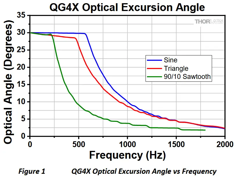
Performance Graphs

![]() Performance graph details:
Performance graph details:
All waveforms were created using raw waveform generator signals. Sine and Triangle waveforms were created with a 50% duty cycle, while the Sawtooth waveform was created using a 90%/10% duty cycle. Performance will vary slightly for the QG4Y and QG5Y galvos due to the Y-axis mirror’s shape and load difference. The lines represent the maximum achievable frequency for a 1 A RMS current draw on the amplifier. The area underneath the lines indicates the recommended operating zones for the corresponding waveforms. Avoid operating the galvo above these lines to prevent damage to the product. Avoid driving the galvo at frequencies higher than those shown in the graphs above. Note that automatic motor shutoff is not provided. For additional support, contact technical support.
Mechanical Drawings


Pin Diagrams
The 9-pin connector carries the two differential position detector signals, the AGC voltage (Oscillator Power), the two motor drive signals, and ground. These signals are sent between the 9-pin connector on the galvo motor and the 3-pin (J6) and 5-pin (J1) connectors on the Class 1 servo amplifier.

Contents of the Box

The table below lists the standard components of the QG4 and QG5 Single-Axis Galvo Systems:

Chapter 2 Safety
Although the unit does not emit radiation, it does redirect laser radiation emitted from other devices. Operators must follow all safety precautions provided by the manufacturer of any associated laser devices.
Safety precautions should be taken to avoid exposure to laser radiation. During system shutdown or malfunction, the scanner can point the beam anywhere within its range of rotation. It is up to the user of these scanners to limit the exit aperture of the laser beam to provide laser safety.
![]() Care must be taken to avoid electrical shock from exposed wiring.
Care must be taken to avoid electrical shock from exposed wiring.
Chapter 3 Installation
Warranty Information
Galvanometer systems are not field-serviceable. Any attempt to modify the galvanometer, including adjusting the mirror position, voids the warranty. Removing and re-attaching optics also voids the warranty. Optical coatings are delicate and are not covered by the standard warranty. Driving the galvo beyond the specified maximum velocity or sending signals outside the specified range will void the warranty. Failure to properly mount the galvo to allow for thermal discharge will also void the warranty. Damage caused by incorrect electrical connections is not covered by the warranty. Do not operate the galvanometer with any other servo amplifier other than the one that it is paired with.
Required Items Not Included
- Mount for Galvanometer Motor (Recommended: QSM4 Mount)
- Heatsink for Servo Amplifier
- Power Supply
- Signal Generator
- Cables for Connecting Servo Amplifier to Signal Generator and Power Supply
![]() Notice: ESD
Notice: ESD
When unpacking the servo drive electronics, caution should be used to protect against static electricity damage. Failure to use proper static protection may cause damage to the servo driver boards and void the manufacturer’s warranty.
Installation Instructions
The instructions below serve as a quick guide. Before attempting to operate, please read chapter 2 for safety precautions and refer to the servo driver manual for additional information and instructions.
Cable Connections
Servo amplifiers are factory-tuned to match a specific motor. Prior to making connections, verify that the serial number on the galvo motor matches the corresponding serial number on the servo amplifier board. This sticker can be found on the white, 3-pin J7 connector of the servo amplifier.

- Identify the 24” (61 cm) Drive and Command Cable Assembly that Comes in the Box
- Connect the 9-Pin Connector to the Base of the Galvo
- Connect the 3-Pin Connector to the Servo Amplifier Position Connector J6
- Connect the 5-pin Connector to the Servo Amplifier Power Connection at J1

Power
Thorlabs recommends using a dual-output, linear power supply capable of outputting power within the range of ±15 V to ±24 V. A power supply capable of supplying 3 A of current should be sufficient for optimal performance. Options for suitable power supplies can be found on Thorlabs.com.
Galvanometers are highly susceptible to electronic noise therefore a power supply capable of outputting <100 mV ripple with <0.5% DC to 30 MHz noise should be used.
![]() Switching style supplies typically exceed acceptable noise levels and are not recommended.
Switching style supplies typically exceed acceptable noise levels and are not recommended.
Mounting
The galvanometers should be mounted in a C-type compression clamp built into a rigid structure. The mounting material used most often is aluminum. Ensure that the mirror can rotate through the full rated excursion without encountering obstacles or other system components. For easy integration with Thorlabs opto-mechanical hardware and optical tables the QSM4 mount is available on Thorlabs.com
![]() Do not over-torque galvos into their mounts. Excessive pressure on the mounting surface may damage the galvanometer body.
Do not over-torque galvos into their mounts. Excessive pressure on the mounting surface may damage the galvanometer body.

Setscrews should not be used to hold galvo motors in fixturing as they are easily overtightened and can damage the stator body.
Heat Sink Requirements
Under most operating conditions, the galvanometer motor will radially transfer its heat from the motor to the mount. Proper contact between the motor mount and body should be maintained to control temperature fluctuations within the system that can contribute to thermal drift.
Temperature changes in the galvanometer environment can cause small amounts of drift in the galvanometer’s position (see Section 1.4.1).
Chapter 4 Operation
Data/Command
The Class 1 servo amplifier for the QG4/QG5 galvanometer is configured to receive analog commands within the range of ±10 V and offers a total excursion range of ±15° optical for the QG4 and ±20° optical for the QG5 galvo systems, respectively. See the separate Class 1 servo amplifier manual for additional details.
Command Voltage Scale Factor:
- 0.67 V/° optical for the QG4 Galvo Systems
- 0.50 V/° optical for the QG5 Galvo Systems
If using BNC cables for data communication, 50 Ω cables should be used.
The galvos can be controlled using a waveform generator or DAQ with analog outputs that connect to the servo amplifiers (see minimum DAQ specifications). The final required signal generator specifications will depend on the application and determine the system’s resolution.
Minimum Recommended DAQ Specifications
- Dual bi-polar -10 V to +10 V DAC analog output channels for differential commandsa.
- Clocking Frequency of 100 kS/s.
- Must be operated in high-Z mode.
Applying Laser Power to the Mirror
- The mirrors on the QG4 are sized to reflect a Ø4 mm 1/e² laser beam through the full rated excursion of ±15° optical without the beam falling off the edge of the mirror.
- The mirrors on the QG5 are sized to reflect a Ø5 mm 1/e² laser beam through the full rated excursion of ±20° optical without the beam falling off the edge of the mirror.
- The mirrors mounted on the system are designed to reflect light within a specified wavelength range (see Section 1.4.2). Before applying laser energy to the mirrors, it is important to confirm that the optic will reflect the wavelength of the laser being used.
- Optical surfaces can be damaged by excessive laser energy. The power and fluence levels of a laser should be confirmed before applying energy to the mirrors. As the laser beam diameter decreases, laser power density increases. Thorlabs recommends expanding laser beams to the full mirror aperture to reduce the possibility of mirror damage.
- Attempting to remove or remount the mirror on the system will negatively impact system performance and void the warranty.
- Before operating the galvo system, the laser should be properly aligned to ensure that the beam lands squarely on the mirror and does not hit the galvo shaft. Depositing laser energy on the motor shaft can increase system temperature and result in hardware failure.
Chapter 5 Maintenance and Cleaning
The QG4 and QG5 galvanometer motors should not require regular maintenance and are not field serviceable. Periodic checks to the optical surface for cleanliness are suggested. Optical coatings are exceptionally delicate and should not be touched. If dust or debris is observed on the mirror surface, optical-grade canned or filtered compressed air may be used to attempt to blow the debris from the surface.
![]() It is important that only optical-grade canned air or compressed air that is filtered to ISO Class 3 or better is used. Many air dusters available from consumer stores can contain particulates and accelerants that can become deposited on the optics if used.
It is important that only optical-grade canned air or compressed air that is filtered to ISO Class 3 or better is used. Many air dusters available from consumer stores can contain particulates and accelerants that can become deposited on the optics if used.
If debris remains on an optic that cannot be blown off, contact-cleaning of the mirror is still not recommended. However, if an attempt at cleaning is going to be made, only reagent grade isopropyl alcohol or acetone should be used, along with a lens tissue or swab that is designed for cleaning scratch-sensitive surfaces. Even if proper care is taken, the fragile nature of optical coatings means the mirror may still be damaged by cleaning. Damaged mirrors are not covered by the manufacturer’s warranty.
Never handle optics with bare hands, as skin oils can permanently damage the optical surface quality.
Chapter 6 Troubleshooting and Repair
Below are a few checks to help in troubleshooting problems that may arise. Please contact your local Thorlabs Technical Support office with any questions.


Chapter 7 Disposal
![]()
Thorlabs verifies our compliance with the WEEE (Waste Electrical and Electronic Equipment) directive of the European Community and the corresponding national laws. Accordingly, all end users in the EC may return “end of life” Annex I category electrical and electronic equipment sold after August 13, 2005 to Thorlabs, without incurring disposal charges. Eligible units are marked with the crossed out “wheelie bin” logo (see right), were sold to and are currently owned by a company or institute within the EC and are not dissembled or contaminated. Contact Thorlabs for more information. Waste treatment is your own responsibility. “End of life” units must be returned to Thorlabs or handed to a company specializing in waste recovery. Do not dispose of the unit in a litter bin or at a public waste disposal site. It is the user’s responsibility to delete all private data stored on the device prior to disposal.
Chapter 8 Thorlabs Worldwide Contacts
For technical support or sales inquiries, please visit us at www.thorlabs.com/contact for our most up-to-date contact information.

Corporate Headquarters
Thorlabs, Inc.
43 Sparta Ave
Newton, New Jersey 07860
United States
sales@thorlabs.com
techsupport@thorlabs.com
EU Importer
Thorlabs GmbH
Münchner Weg 1
D-85232 Bergkirchen
Germany
sales.de@thorlabs.com
europe@thorlabs.com
Product Manufacturer
Thorlabs Measurement Systems, Inc.
34 B Londonderry Rd.
Londonderry, NH 03053
United States
sales@thorlabs.com
techsupport@thorlabs.com
UK Importer
Thorlabs Ltd.
204 Lancaster Way Business Park
Ely CB6 3NX
United Kingdom
sales.uk@thorlabs.com
techsupport.uk@thorlabs.com
Documents / Resources
 |
THORLABS QG4X-AG Galvo Scan Head and Controller [pdf] User Guide QG4X-AG Galvo Scan Head and Controller, QG4X-AG, Galvo Scan Head and Controller, Scan Head and Controller, Head and Controller, Controller |