![]() Genesis Duo™
Genesis Duo™
Dual-Point Control & Monitoring Solution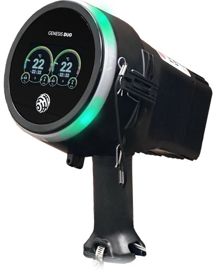 INSTALLATION GUIDE
Genesis Duo Dual Point Control and Monitoring Solution
Version History
| Version | Comments | Document Number |
| V1.2 | Revised version includes section on Maintenance Procedures | PN50900-1124 |
| V1.1 | Revised version of the Genesis Duo Installation Guide includes p. 8 Notes on cable routing | PN50900-0624 |
| V1.0 | Base version of the Genesis Duo Installation Guide | PN50900-0324 |
Genesis Duo ™
Introduction
This guide provides a detailed step-by-step installation procedure to install, set-up and configure Genesis Duo. This guide is in English. For local language translation version, please contact your local sales representative.
Audience
The information in this guide is intended for engineers and technicians qualified for the installation and programming of heat trace controllers. You should have certified technician skills or have a background:
- To carry out electrical system installations
- Basic understanding of electrical and electronic systems
- Experience installing Heat Trace Systems
- Basic understanding of the working of heat trace controller and configuration settings
- Usage of mechanical tools
Installation Precautions
- To minimize the potential for arcing and fire caused by product damage or improper installation use ground-fault protection. The National Electrical Code (NEC) and Canadian Electrical Code (CEC) require ground-fault protection of equipment for each branch circuit supplying electric heat tracing.
- Installation must comply with Thermon requirements and be installed in accordance with the NEC, CEC, or any other applicable national and local codes.
- Component approvals and performance ratings are based on the use of Thermon specified parts only. User supplied power connection fittings must be listed or certified for intended use.
- Deenergize all power sources before opening the enclosure.
- Keep ends of heating cable and kit components dry before and during installation.
- Individuals installing these products are responsible for complying with all applicable safety and health guidelines. Proper personal protective equipment, or PPE, should be utilized during installation. Contact Thermon if you have any additional questions.
Product Details
- Product Description
Genesis Duo is a dual-point control and monitoring solution for heat tracing applications. It is used to control heat trace in freeze protection and process control application and communicate status to other platforms via wired and/or wireless communication interfaces on-board. - Technical Specifications
Environmental Characteristics: Operating Temperature: Ta a -40°C s Ta s +60°C Module relative humidity range: 0 to 90% Non-Condensing Maximum Altitude 2000m Installation Category Category II Pollution degree 2 OvervoItage Category Category Ill Usage locations Indoor and Outdoor Usage in Wet Condition Yes Power Specifications: Input Voltage Rating: 100-277VAC, *10%, 50•60Hz, switching power supply module supplies control hardware Input Power Rating: 55 Watts Max Relay Rated Current: 30A for ambient less than 55°C. 25A for ambient between 55°C and 60°C Short Circuit Current: 3.15 Amps Particulars: Classification of installation and Use: Stationary Communication Interfaces: 10/100 Ethernet lx 802.15.4 Radio lx USB Host lx Wi-Fi Radio lx (802.11 b/g/ ) RS-485 Full Duplex lx - Product Models
Part Number Model Code Description 816011 GN-D-S-S-T-C-Z-XP Genesis Duo w/LCD, Current Monitoring (2 SSR) + Pipe Mount Kit 816012 GN-D-S-S-T-C-Z-WP Genesis Duo w/LCD, Current Monitoring (2 SSR) + Wall Mount Kit 816021 GN-D-M-M-0-0-Z-XP Genesis Duo w/o LCD (2 Mechanical) + Pipe Mount Kit 816022 GN-D-M-M-0-0-Z-WP Genesis Duo w/o LCD (2 Mechanical) + Wall Mount Kit 816051 GN-D-S-S-0-C-Z-XP Genesis Duo w/o LCD, Current Monitoring (2 SSR) + Pipe mount Kit 816052 GN-D-S-S-0-C-Z-WP Genesis Duo w/o LCD, Current Monitoring (2 SSR) + Wall mount Kit - Certifications/Approvals
 -40°C < Tamb < +60°C; IP66
Class I, Zone 2, AEx/Ex ec mc nC [ib Gb] IIC T4 Gc
 Zone 22, AEx/Ex tc IIIC T135°C
Class I, Division 2, Groups A, B, C, D; T4
 Class II, Division 2, Groups FG; Class III; T135°C
 Ex ec mc nC [ib Gb] IIC T4 Gc
Ex tc IIIC T135°C Dc
II 3(2) G Ex ec mc nC [ib Gb] IIC T4 Gc
II 3 D Ex tc IIIC 135°C Dc
Preparing the Duo for Installation
- Receiving, Storing and Handling
a. Identify parts against your packing list to ensurthe proper type and quantity has been received.
b. Inspect materials for damage incurred during shipping.
c. Report damages to the carrrier for settlement
Kit Contents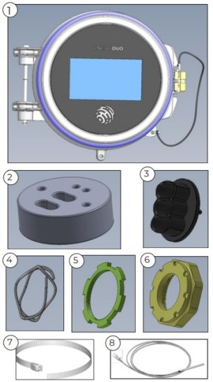
Item Quantity Description 1 1 Genesis Duo Unit 2 1 Grommet 3 1 Cable Guide 4 1 Wave Spring 5 1 Lock Ring (2.25″) 6 1 Lock nut (2.26″) 7 1 B-10 Metal banding 8 Not included 3-Wire RTD(s) – Order separately Notes:
1 – The Duo unit may or may not have a graphical display depending on your unit’s model code.
2 – The Duo unit with mechanical relays will not have a heat sink. The form factor will be different for that model.
3 – The actual grommet you order and use will depend on the type of heat trace cable you plan to use in your installation. Refer to Appendix A Form PN50900-1124
Pipe Mount or Wall Mount Expediter Kit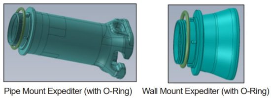 3-wire RTD(s) – NOT included. Must be ordered separately.
b. If any of the ordered items are missing, please contact your Thermon sales representative immediately for a replacement order.
Note: You will need to return all the items in the received package against a replacement order. Please discuss the logistcs with your Thermon sales representative.
Pipe Mount expediter assembly (Component positioning)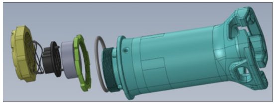 Wall Mount expediter assembly (Component positioning
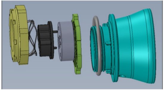
- Tools Required
Ensure availability of the following tools needed for the installation, assembly and mounting of Genesis Duo and the RTD wiring for each circuit. (not included in package).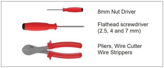 Torque Specifications:
Phoenix terminal UT-6: 1.5 Nm to 1.8 Nm
Current Transformer (CT) bracket #10 screw: 1.7 Nm to 1.9 Nm - Unpacking Contents
a. Remove components from the package
b. Set aside the required quantity of RTDs as needed for circuit configuration
c. For pre-drilled entries as shown below (1-inch clearance/M25 clearance) to be used for routing cables/wires, select a cable entry that complies with your local region’s code.
.d. Refer to the Genesis Duo Wiring System Diagramswhile making wiring connections. Note: The dust covers received with the Duo do not ensure the IP rating. They must be replaced during installation procedure with rated blind plugs.
 - Open the Duo Cover
 a Pull the string to remove locking pin.
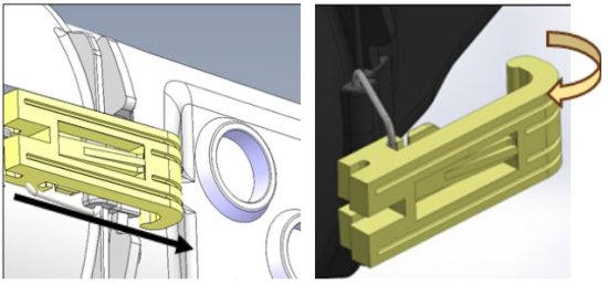 b. Push latch forward to release and unlock Duo cover.
Tip: Avoid using too much force as the latch may come off. If it does, replace it back in position. c. Use a 4mm or larger flathead screwdriver for leverage to open the tightly sealed Duo cover.
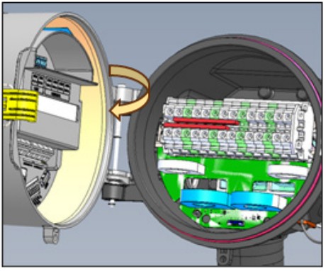 d. Move the cover clockwise all the way to left, until there is an audible “click.” This will lock the cover in position.
 - Remove the Terminal Block
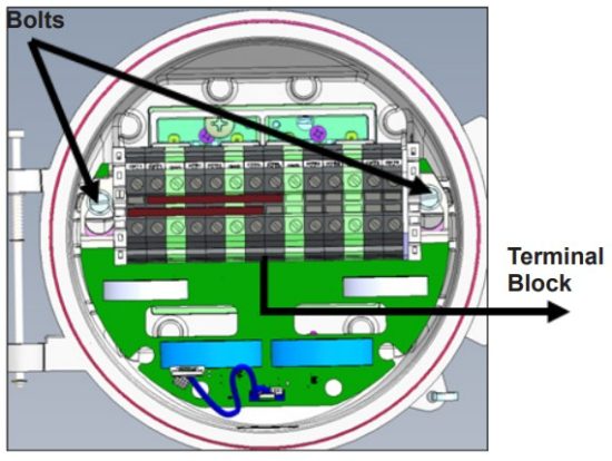 a. Use the 5/16’’ nut driver to loosen bolts holding the terminal block.
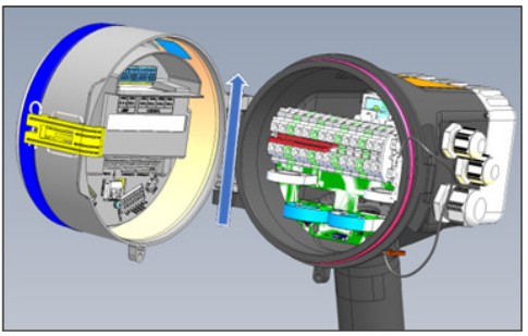
Tip: Do not fully remove bolts.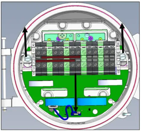 b. Remove Terminal Block assembly by sliding it up from bolts, pulling it out of the enclosure to access the rear area.
CAUTION: Do not strain the wires while pulling the terminal block. CAUTION: Do not place the terminal block on top or in between the cover and main body. It can fall and cause injury to your hand.
Tip: Place the Duo on the surface with the heat sink as the base.
Support the Duo cover from the side for stability. Pull the terminal block out and let it weigh toward bottom. - Install Cable Glands
 a. Install required number of cable glands depending on number of clearance holes to be used for wiring. The cable gland should accommodate the thickness of wires passing through it.
Caution: Customer is responsible for installation of certified-rated cable glands appropriate for the installation environment to maintain specifications. If improper glands are installed, Thermon is not responsible for nonconformance.
Tip: Use certified glands with proper IP rating depending on the environment where you plan to install the Duo. If not ordered, procurement of those will be customer’s responsibility.
b. Install rated blind plugs in all unused holes to maintain required rating for the environment. - Jumper Connections on the Terminal Block
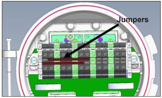 a. Identify the jumper configuration for your setup.
The jumper settings combine or isolate circuits with respect to individual breakers.
Note: Duo ships with default jumper connections with CTRL points shorted to corresponding Ckt 1 points
Refer to: Genesis Duo Wiring System Diagrams
b. Pre-installed red jumpers are removable and can be re-used for jumper connections.
Remove the default jumpers if needed.
Tip: Recommend using wires for ease in making jumper connections.
d. Duo is now ready to mount on pipe or wall mount assembly.
DUO INSTALLATION PROCEDURE
- Mounting Assembly
1.a. Pipe Mount i. Inspect grommet for defects and debris. If covered in debris or powder, use a light cleaning agent and rag to remove it. Rinse and fully dry before continuing. Verify cable gland model matches heat trace gland model per Appendix A.
 ii. Locate bus connection (HPT and FP only) and cable as shown.
iii. Cut the end of the cable at an angle to aid in piercing grommet. iv. Run the heat trace cable through the bottom of the expediter base (pipe mount). Take care while feeding the heat trace cables through the expediter guide rails to ensure no twisting occurs.
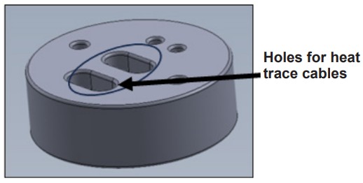 v. Pierce the heat trace cable’s edge (cut) through the grommet to make sure it passes through one of the holes in the grommet.
Notes:
1 – For making heat trace cable connections through the cable glands (via predrilled holes), cold leads must be routed to a cold/hot junction in the field. Heat trace cables cannot be routed directly through the glands into the Duo.
2 – Some of the images shown in this guide might make use of an older version of the pipe mount expediter. Please refer Pipe Mount expediter assembly portion in Receiving, Storing and Handling for the details on the latest expediter.
The installation steps remain the same.
vi. Repeat steps ii and iii for the second heat trace cable if you are configuring two circuits.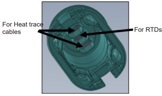 Tip: For ease of wiring, recommend running heat trace cables through corner holes and RTDs through center hole from the base of the expediter as shown in figure above..
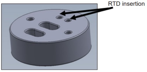 vii. Insert the RTD sensor leads (if using in the circuit) through the expediter bottom, all the way into the corresponding holes in the grommet.Max RTD cable diameter is 0.125″, min RTD cable diameter is 0.10″.
Note: The customer must order RTDs separately. RTDs are not included in Duo or mounting kits shipment.
CAUTION: Do not pull from the sensor end when routing through the expediter assembly.
Pull sensor from the lead wire portion. viii. Pull cables through the grommet. Then push the grommet to make it rest firmly on the expediter.
Tip: Ensure that there is at least 13’’ of RTD cable and 8’’ of heat trace cable exiting the top of the expediter.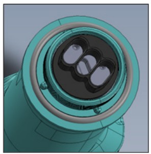 ix. Install the cable guide on top of the grommet.
Pass the heat trace cables and the RTD sensor wires through the corresponding holes of the cable guide as in the grommet.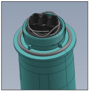 x. Install the wave spring on top of the cable guide.
Ensure that all wires run through it.
Refer to: installation instructions for power connection boot on Thermon Electrical Heat Tracing Cables.
xi. Prepare the heat trace cables for making the electrical connection to the heater circuit on the Duo terminal block.
CAUTION: Use insulating tape to cover exposed portions of the heat trace shield to prevent accidental shorting against RTD metal body. xii. Push the expediter downwards towards the pipe to ensure stable positioning on the pipe.
Tip: All cables must have already been run through the expediter base entry all the way up through the wave spring. xiii. Insert metal banding into the expediter and wrap around pipe. Insert the other end of the band through the hole below the screwhead.
Tip: Ensure that the screwhead is easily accessible to enable tightening. If the Duo is mounted on top of the pipe, the screwhead should be located at the bottom of the pipe.
CAUTION: Ensure that the banding is not placed on top of any cables.
CAUTION: Excess metal band should be cut using a wire cutter.
While cutting the metal band, please ensure that the edge is not left exposed. It can cause injury through cut if exposed to hand or any other body part.
xiv. Run the heat trace cable along the pipe for the needed length.
xv. Cut off the end of heat trace cable running along the length of the pipe. Terminate heat trace cable with an appropriate termination kit.
Refer to: Thermon End Termination Kit Installation instructions.
xvi. Push excess cable back through expediter. Use care while feeding the heat trace cables through the expediter guide rails to ensure the cables do not become twisted.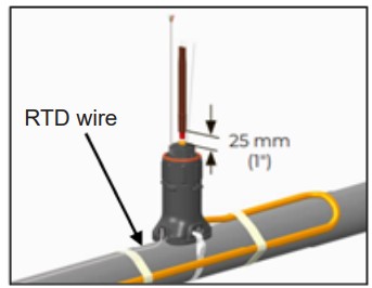 xvi. Tape cable expansion loop to pipe.
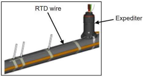 xvii. Fix the RTD sensor head to the pipe using fixing tape
Tip: Use fixing tape according to Thermon heat trace cable specifications.
Refer to: Thermon fixing tapes FT-IL, FT-IH xviii. Mount the Duo body on the expediter carefully. Align slots with the protrusions on the expediter to properly orient junction box base.
Ensure that the main housing rests properly on the top of the expediter’s O-ring seal.
Tip: Pull the terminal block upwards to the top with one hand to make the rear accessible. With the other hand pull all wires coming in through the expediter together towards the bottom.
CAUTION: Hold the terminal block firmly towards the top. If it falls, it can cause injury to your hand.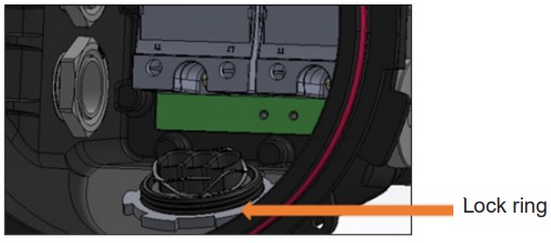 xix. Ensure all wires from the expediter pass through the lock ring. Place the lock ring on the expediter assembly. Lock the ring by turning it clockwise.
Tip: Make sure that the flat side is towards the bottom. Tighten as much as possible using your fingers. Using a marker, place a mark at the ending location once tightened. .After that, use pliers to ensure that it is tightened fully or use a mallet and flat head screwdriver to tighten the metal nut,driving it clockwise until tight.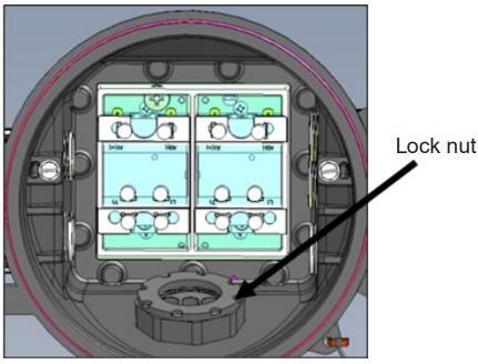 xx. Install the lock nut on top of the lock ring. Ensure that the circular side with the locknut grooves is on the top and the flat side is at the bottom.
Tip: Apply force to compress the wave spring and then tighten it clockwise.
Use fingers and then a wrench to tighten fully.
xxi. Now that assembly is complete, proceed to wiring connections.
1.b. Wall Mount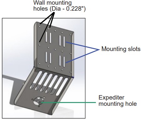 i. Identify and mark the position of the wallmounting holes on the wall using the holes to ensure proper distance between them.
ii. Drill the holes in the wall (at the location where you want to mount the unit) for the given dimension using appropriate drill bit.
iii. Mount the bracket on the wall by placing the appropriate fasteners through the wall mounting holes. iv. Secure the bottom of the expediter to the bracket using the provided spring washers and bolts.
v. Follow the Duo installation steps as outlined in the Pipe Mount section of the Mount Assembly. - Wiring Connections
2.a. RTD Wiring
i. Refer to the Duo wiring diagrams for your preferred configuration.
Refer to: Genesis Duo Wiring System Diagrams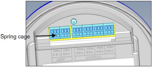 ii. Connect the RTD wires to the appropriate point with the marked label on the front cover.
Note: Red wire – B, White wire – A
Tip-1: Route the RTD wires towards the direction of the open Duo cover (i.e. left). Leave enough length on RTD wires inside the Duo to facilitate movement when the Duo cover is opened or closed.
Tip-2: Engage the spring-cage at the bottom using the 2.5 mm flathead screwdriver.
Do not use excessive force; just enough to open the corresponding receptacle/socket by pressing at the bottom and lifting a little. Insert the RTD wire.
CAUTION: If the RTDs being used have a metal casing like RTD-500-72-3, we strongly recommend taping the wire to the inside of the Duo to prevent them from touching the metal backplate on the terminal block and causing a short.
2.b. Alarm Wiring
i. Route alarm wires through the convenient cable gland from either side into the Duo leading up to the Alarm relay port. ii. Connect the alarm output wires to the alarm relay port available (as shown above).
Tip: Engage the spring-cage at the bottom using the 2.5 mm flathead screwdriver. Do not use excessive force; just enough to open the corresponding receptacle/socket by pressing at the bottom and lifting a little. Insert the alarm wire.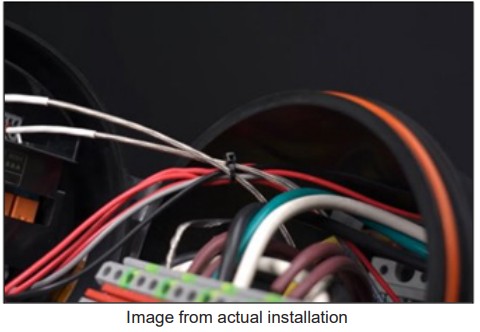 Tip: Use a cable tie to secure wires near top of the Terminal Block assembly to avoid clutter.
2.c. Heater Wiring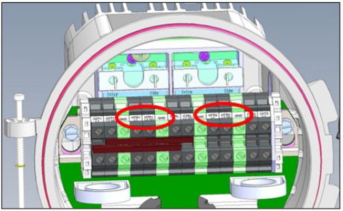 i. Connect the heat trace cables on the back of the terminal block to the appropriate label position (as per the wiring diagram)
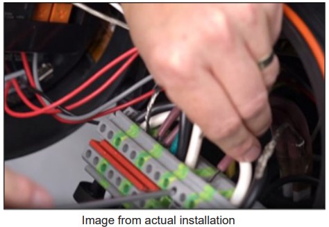 2.d. Power Wiring
i. Route the power wires through the convenient cable gland from either side of the Duo to the back of the terminal block.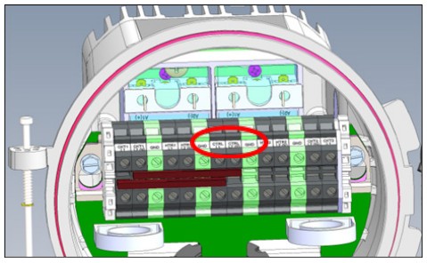 ii. Connect the power wires to the corresponding labels (CTRL L1/CTRL L2(N)/GND) in the terminal block. .
Tips:
1 – Use 4mm flathead screwdriver to secure wires to terminal block.
2 – Line to CTRL L1, Neutral to CTRL L2(N) & Ground to GND.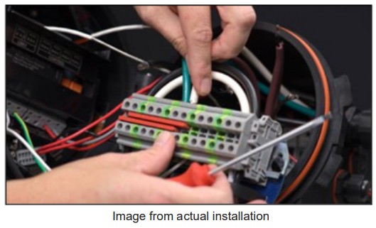
- Secure the Terminal Block
a. Once all wiring connections to the terminal block are complete, use a zip tie to tidy the wiring going into the Duo cover.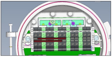 b. Carefully push the terminal block assembly back into the Duo housing to rest on the two mounting bolts. Tighten each bolt using the 5/16’’nut driver.
Tip: While pushing the terminal block in, route the power/alarm/RTD wires from top of the terminal block to avoid obstruction by them. - Close and Lock Duo Cover
 a. Lift the cover vertically to release it from the locked position.
Caution: Ensure that the wires going to the Duo cover are routed from the top of the terminal block before attempting to close the cover. Ensure that no wires are pinched in the process. b. Close the cover.
Tip: You may need to use pliers to squeeze the door against the body until properly sealed/closed. c. Close the latch.
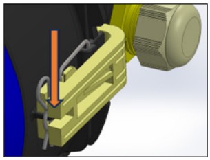 d. Insert the pin.
e. Congratulations! Your Duo installation is now complete. You can power up the device. - Power
a. Power up the Duo device.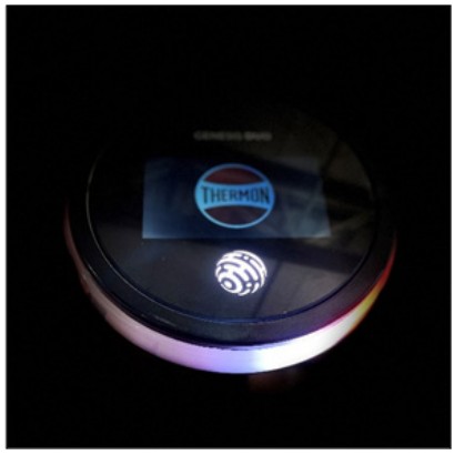 b) The clockwise and anti-clockwise rotation of red and white patterns on the outer ring indicates that the device is booting up.
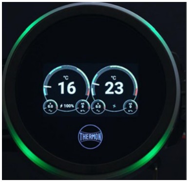 c) When the outer ring changes to a steady green state, it indicates that the power up sequence is complete. The Duo is ready to update configuration settings.
d) If you have connected RTDs to both the circuits, you will notice that when the device is powered up for the first time, you only see the temperature showing up for circuit 1 on the left side.
e) The 2nd circuit on the right shows disconnected. This is the default state after the first time boot up sequence.
f) Once the configuration settings are done for both the circuits, you will see the parameters for both the circuits.
Refer to: Genesis Controller Settings for configuration.
Genesis Duo Controller Settings
| Setting Option | Applies To | Function | User Selectable Setpoints | Comments: | |
| 1 | Circuit Tag | Individual Circuit | Circuit Identifier | 0 to 64 Characters | only the last 33-34 characters show on the menu screen |
| 2 | Power State | Individual Circuit | Circuit State | Disabled or Enabled or Forced on or Forced off | |
| 3 | Active Alarms | Individual Circuit | Circuit Alarms | N/A | |
| 4 | Temperature Settings | ||||
| 5 | Low Temperature Alarm | Alarms | Low Temperature Alarm | -76F to 932F | |
| 6 | Maintain Temperature | Set Point | Maintain Temperature | -76F to 932F | |
| 7 | Max Temperature | Deadband | Temperature Deadband | -76F to 932F | |
| 8 | High Temperature Alarm | Individual Circuit | High Temperature Alarm | -76F to 932F | |
| 9 | High Temperature Trip Mode | Individual Circuit | Trip or High-High Alarm Selection | High Temperature Trip or High-High Alarm | When one selection is made, the other setting does not show in the menu. |
| 10 | High Temperature Trip | Individual Circuit | High Temperature Circuit Trip | -76F to 932F | |
| 11 | High-High Temperature Alarm | Individual Circuit | High-High Temperature Alarm | -76F to 932F | |
| 12 | Temperature Alarm Delay | Unit | Temperature Alarm Delay | Disabled to 30 mins | |
| 13 | Temperature Units | Unit | Temperature Units | C or F | |
| 14 | Current Settings | ||||
| 15 | Low Current Alarms | Individual Circuit | Low Current Alarm (Amps) | 0.0 to 100.0 A | |
| 16 | High Current Alarm | Individual Circuit | High Current Alarm (Amps) | 0.0 to 100.0 A | |
| 17 | High Current Trip Mode | Individual Circuit | Trip or High-High Alarm Selection | Trip or High-High Current Alarm | When one selection is made, the other setting does not show in the menu. |
| 18 | High Current Trip | Individual Circuit | High Current Trip (Amps) | 0.0 to 100.0 A | |
| 19 | High-High Current Alarm | Individual Circuit | High-High Current Alarm (Amps) | 0.0 to 100.0 A | |
| 20 | Current Alarm Delay | Unit | Alarm Delay (Minutes) | Disabled to 7 mins | |
| 21 | Max Current (Heater OFF) | Unit | Max Current (Heater OFF) (Amps) | 0.0 to 50.0 A | |
| 22 | Ground Current Settings | ||||
| 23 | High Ground Current Alarms | Individual Circuit | High Ground Current Alarm (mA) | 0 to 200 mA | |
| 24 | High Gnd Current Trip Mode | Individual Circuit | Trip or High-High Alarm Selection | Trip or High-High Alarm | When one selection is made, the other setting does not show in the menu. |
| 25 | High Ground Current Trip | Individual Circuit | High Ground Current Trip (mA) | 0 to 200 mA | |
| 26 | High-High Gnd Current Alarm | Individual Circuit | High-High Gnd Current Alarm (mA) | 0 to 200 mA | |
| 27 | Ground Samples Before Trip | Unit | Ground Fault Samples Before Trip (number) | 1 to 10 | |
| 28 | Control and Power Settings | ||||
| 29 | Control Method | Individual Circuit | Control Mode | On/Off or On/Off w/ Soft Start or Proportional or Ambient On/Off or Ambien Proportional-Mechanical | |
| 30 | Control RTDs | Individual Circuit | Number of Control RTDs | 1 to 4 (BBA) | |
| 31 | Power Clamp | Individual Circuit | Power Clamp % | 0 to 100 % | |
| 32 | Power on RTD Fault | Individual Circuit | Power on RTD Fault % | 0 to 100 % | |
| 33 | Global Settings | ||||
| 34 | Start Up Delay | Unit | Start Up Delay (minutes) | Disabled to 30 mins | |
| 35 | Self-Test Interval | Unit | Self-Test Interval (hours) | Disabled to 168 HR | |
| 36 | Modbus Map Type | Mapping | TCM 2 or TC202 | Requires Reboot for setting change to take effect. | |
| 37 | Modbus Slave ID | Modbus Identifier | 1 to 247 | Requires Reboot for setting change to take effect. | |
| 38 | Modbus Mode | Modbus Mode | RTU (8n1) or ASCII (7n2) | Requires Reboot for setting change to take effect. | |
| 39 | Modbus Baud Rate | Baud Rate | 9600 or 19200 or 115200 | Requires Reboot for setting change to take effect. | |
| 40 | Controller type | Unit | Type of Controller | Default or 1 Circuit or 2 Circuit or 1 Circuit w/ Limiter | Requires Reboot for setting change to take effect. |
| 41 | Display Brightness | Unit | Brightness | 10 to 100 | |
| 42 | Screen Saver Delay | Unit | Brightness Delay (min) | Disabled to 180 min | |
| 43 | Change Access Code | Unit | Access Code | 4-digit code (0 to 9) | |
| 44 | Logout | Unit | Logout | No or Yes | Prompt- “Logout now?” |
| 45 | Reboot | Unit | Reboot | No or Yes | Prompt- “Reboot now?” |
| 46 | **Info | Unit | Unit Information | Various Parameters | Section below will note all parameters found under this setting. |
| **Setting- Info Menu | ||
| Information | Unit | Comments |
| System | ||
| Line Voltage | V | |
| PCB Temperature | C or F | Depending on setting chosen for “Temperature Units” |
| LED Temperature | C or F | Depending on setting chosen for “Temperature Units” |
| Time in Operation | HR | |
| Circuit 1 | ||
| Power Rate | A/Hr | |
| Power Total | Wh | |
| RTD 1 Reading | C or F | Depending on setting chosen for “Temperature Units” |
| RTD 2 Reading | C or F | Depending on setting chosen for “Temperature Units” |
| Circuit 2 | ||
| Power Rate | A/Hr | |
| Power Total | Wh | |
| RTD 1 Reading | C or F | Depending on setting chosen for “Temperature Units” |
| RTD 2 Reading | C or F | Depending on setting chosen for “Temperature Units” |
| **Setting- Info Menu | ||
| Information | Unit | Comments: |
| System | ||
| Line Voltage | V | |
| PCB Temperature | C or F | Depending on setting chosen for “Temperature Units” |
| LED Temperature | C or F | Depending on setting chosen for “Temperature Units” |
| Time in Operation | HR | |
| Circuit 1 | ||
| Power Rate | A/Hr | |
| Power Total | Wh | |
| RTD 1 Reading | C or F | Depending on setting chosen for “Temperature Units” |
| RTD 2 Reading | C or F | Depending on setting chosen for “Temperature Units” |
| Circuit 2 | ||
| Power Rate | A/Hr | |
| Power Total | Wh | |
| RTD 1 Reading | C or F | Depending on setting chosen for “Temperature Units” |
| RTD 2 Reading | C or F | Depending on setting chosen for “Temperature Units” |
Maintenance Procedure for the Duo
Recommended Visual Inspection
- Examine the unit for dust, lint, moisture, grease or foreign residue
- Inspect the unit for dust and water intrusion if indicated by any mineral deposits and rust. When openin and closing the unit, refer to V.4. Open the Duo Cover and VI.4. Close and Lock Duo Cover in this documIf the unit needs to be opened for servicing, please ensure that the unit is powered OFF and the area is f of explosive atmospheres.
- Use a damp cloth to wipe the outside of the unit in case of dust or grease accumulation on the display or on the light ring.
- Ensure that the blind plugs are installed for the unused holes to maintain the unit’s IP rating.
- Ensure that the cable glands are properly tightened on all the used holes using the recommended tor specifications.
- A visual inspection is not a functional inspection. If the unit is not functional, please contact Thermon.
Wiring and Connections Survey
- If the unit needs to be opened for servicing, please ensure that the unit is powered OFF and the area is free of explosive atmospheres. Maintenance can include a firmware upgrade, which must be completed under voltage.
- If possible, do an infrared scan of the interior of the unit while unit is powered. Any unusually high temperatures (outside the specification range) can indicate poor wiring connections.
- Inspect wiring for abrasive wear, mechanical damage, and thermal overexposure. Repair or replace any damaged or defective wiring. In all cases where unit damage is observed, a root cause analysis should be initiated to determine if any corrective action is needed to prevent a recurrence.
- All terminal block connections should be inspected and ensured that they are tightened as per instructions. Refer to VI.2.2a. RTD Wiring, VI.2.2b. Alarm Wiring, VI.2.2c. Heater Wiring, VI.2.2.d. Power Wiring, and VI.3. Secure the Terminal Block in this document for detailed instructions.
- Check the unit for corrosion. Where corrosion of electrical terminals is observed, this may be additional evidence of moisture ingress, loose connections, and excessive heat. A part replacement may be necessary.
- If the unit is not functional, please contact Thermon.
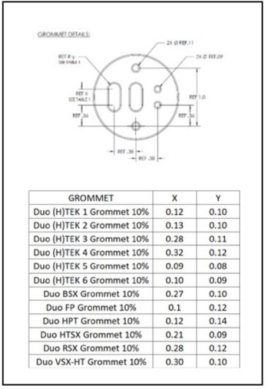
Appendix A – Grommet Specifications
Corporate Headquarters: 7171 Southwest Parkway
Building 300, Suite 200
Austin, TX 78735
Phone: 512-690-0600
For the Thermon office nearest you visit us at . . . www.thermon.com
Form PN50900-1124
© Thermon, Inc.
Information subject to change.
1.2
![]()
Documents / Resources
 |
THERMON Genesis Duo Dual Point Control and Monitoring Solution [pdf] Installation Guide PN50900-1124, PN50900-0624, PN50900-0324, Genesis Duo Dual Point Control and Monitoring Solution, Genesis Duo, Dual Point Control and Monitoring Solution, Point Control and Monitoring Solution, Monitoring Solution, Solution |