 TEAM ASSOCIATED RC10B7 Team Kit

Specifications
- Manufacturer: Associated Electrics, Inc.
- Address: 21062 Bake Parkway, Lake Forest, CA 92630
- Customer Service Tel: 949.544.7500
- Fax: 949.544.7501
Product Features
- Button Head, Flat Head, Cap Head screws
- Ball Bearings in various sizes
- Shims, Washers, Ballstuds, Set Screws, Nuts, Locknuts
- Special assembly notes and symbols for instructions
Introduction
Thank you for purchasing this Team Associated product. This assembly manual contains instructions and tips for building and maintaining your new vehicle. Please take a moment to read through the manual and familiarize yourself with the steps. We are continually changing and improving our designs; therefore, actual parts may appear slightly different than the illustrations. New parts will be noted on supplementary sheets located in the appropriate parts bags.
- Check each bag for these sheets before you start to build.
- Check www.AssociatedElectrics.com for the latest versions of our instruction manuals.
RC10B7 Team Kit Features
- 5-gear laydown transmission with low profile motor mount moves the weight of the motor closer to the center of the car
- Long-arm suspension geometry improves grip and predictability in all conditions
- KPI adjustable steering and caster blocks allow for fine-tuning steering feel. Three options are included in the kit.
- Vertical front outer ball stud allows fine-tuning of roll center, camber gain, and link length
- Height adjustable aluminum front bulkhead allows for further tuning of front roll center
- Standard and HRC (High Roll Center) rear hubs included
- High volume gear differential improves the consistency of differential action over a longer run. Fits LTC internal diff gears from the RC10B74.2.
- Highly adjustable battery holder with thumb tabs allows for easy battery removal and fine-tuning of weight bias
- 7075-T6 aluminum chassis with increased departure angle and optional weight plate pockets
- Easy access to anti-roll bars front and rear
- 6.5mm aluminum front axle increases stability and grip when using slim front wheels and low-profile tires
- HD 69mm CVA bones and differential outdrives for improved durability
Additional
Your new RC10B7 Team Kit comes unassembled and requires the following items for completion (refer to www.AssociatedElectrics.com and www.Reedypower.com for suggestions):
- R/C two channel surface frequency radio system
- AA-size batteries for transmitter
- Electronic Speed Control (“ESC”)
- Steering servo
- R/C electric motor (540 size)
- Pinion gear (48P), size determined by type/turn or kV of motor
- Battery charger (a peak detection charger, or LiPo compatible charger)
- 2 cell LiPo battery pack
- Polycarbonate specific spray paint
- Cyanoacrylate glue (“CA”) (#1597)
- Thread locking compound (#1596)
- Tires and Inserts, Fronts and Rears
- Wheels w/12mm Hex
Front Wheels #9690 (white), #9691 (yelllow) Rear Wheels #9695 (white), #9696 (yelllow) - Slim Front Wheels w/12mm Hex (carpet/astro turf) #91757 (white) #91758 (yelllow)
Other Helpful Item
- Silicone Shock Fluid (Refer to AssociatedElectrics.com for complete listings)
- Green Slime shock lube (#1105)
- FT Turnbuckle Wrench, 4mm (#1112)
- FT Body Reamer (#1499)
- Shock Pliers (#1681)
- Wire Cutters
- FT Hex/Nut Wrenches (#1519)
- FT Ballcup Wrench (#1579)
- Hobby Knife
- Needle Nose Pliers
- FT Universal Tire Balancer (#1498)
- Calipers or a Precision Ruler
- FT Body Scissors (#1737)
- Soldering Iron
Hardware
Scale View

Notes

INSTALLATION INSTRUCTION
Bag 1
Step 1

Step 2 
Step 3

Bag 2
Step 1

Step 2

Step 3

Step 4

Step 5

Step 6
Step 7

Step 8
- Line up the front tower cover on the shock tower at an angle as shown in the 1st image to the right.
- Press fi rmly down on the center of the shock tower cover.
Be sure to keep the tower cover centered on the tower. - The cover should snap into place with the tap locking on the back side of the tower.
NOTE: The tower cover was designed to key into place with the supplied LP SHCS. Use of another screw type is not recommended

WARNING: #92417 – Front Wing Mount is used as a tuning option to increase front end stability by adding a front wing (included). If you do not use #92417, use #25202 M3x10mm FHCS instead of #25203 M3x12mm FHCS
Bag 3
Step 1

Step 2

Step 3

Bag 4
Step 1

Step 2

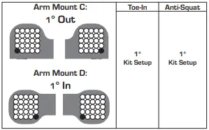
WARNING: The (#92432) C and (#92433) D aluminum arm mounts allow for a large amount of setup combinations when using the (#92014) 0.5° and 1° arm mount inserts.
For a complete list of pill setup combinations, please visit our website by using the link below. http://bit.ly/B6PillChart
Bag 5
Step 1

Step 2 
Step 3

Bag 6
Step 1

Step 2
WARNING:
Note the order of assembly.
Note: The orientation of set screws should face away from the gearbox. Insert one collar and bar, then add a second collar for installation. Center anti-roll bar. Do not overtighten!
Do not over-tighten the anti-roll bar set screws.
The anti-roll bar should rotate freely in the assembly.

Step 3

Step 4

Step 5

Step 6

Bag 7
Step 1

Step 2

Step 3

Bag 8
Step 1

Step 2

Step 3
Bag 9
Step 1

Step 2

Step 3

Step 4

Shock Bleeding Steps
- Before assembly, get each bleed screw and thread it 1-2 turns into the shock cap, then remove the screw. This will make it easier when you are bleeding your shocks.
- Pull shock shaft down.
- Fill shock body 3/4 full with silicone shock fl uid.
- Slowly move the shock shaft up and down to remove air from under the piston.
- Wait for bubbles to come to surface.
- Fill shock body to top with silicone shock fl uid.
- Place a drop of oil in the cap and on cap threads.
- Install cap (without bleed screw) and tighten completely.
- Slowly compress shaft all the way to bleed excess silicone shock fl uid out the hole in the cap (use ragaround shock to catch excess fluid).
- Install M2x4mm button head screw until snug while shaft is fully compressed.

Step 5

Step 6

Step 7

Step 8

Bag 10
Step 1
Step 2

Step 3

WARNING: Standard and Low Profi le battery thumb screws are included. Shims may need to be added if battery weights are used.
- Use M3 x 18mm for standard height
- Use M3 x 12mm LP height

Step 4

Step 5

Step 6

Tuning Tips
Painting, Beginners
Painting:
Your Kit requires a clear polycarbonate body. You will need to prep the body before you can paint it.
Wash the INSIDE thoroughly with warm water and liquid detergent (do not use any detergents with scents or added hand lotion ingredients!).
Dry the body using a clean, soft, lint-free cloth. Use the supplied window masks to cover the windows from the INSIDE of the body (RC bodies get painted on the inside). Using high quality masking tape, apply tape to the inside of the body to create a design. Spray (use either rattle can or airbrush) the paint on the inside of the body (preferably dark colors fi rst, lighter colors last). NOTE: ONLY use paint that is recommended for (polycarbonate) plastics. If you do not, you can destroy the body! After the paint has completely dried (usually after 24 hours), cut the body along the trim lines. Make sure to drill or use a body reamer to make the holes for the antenna if needed! Use hook and loop tape to secure the body to the side rails of the vehicle
Tips for Beginners:
Before making any changes to the standard setup, make sure you can get around the track without crashing. Changes to your vehicle will not be benefi cial if you can’t stay on the track. Your goal is consistent laps. Once you can get around the track consistently, start tuning your vehicle. Make only ONE adjustment at a time, testing it before making another change. If the result of your adjustment is a faster lap, mark the change on the included setup sheet (make adddtional copies of the sheet before writing on it). If your adjustment results in a slower lap, revert back to the previous setup and try another change. When you are satisfi ed with your vehicle, fi ll in the setup sheet thoroughly and fi le it away. Use this as a guide for future track days or conditions. Periodically check all moving suspension parts. Suspension components must be kept clean and move freely without binding to prevent poor and/or inconsistent handling.
Rear Arm Mount Pill Insert Setup

Motor Gearing
Proper motor gearing will result in maximum performance and run time while reducing the chance of overheating and premature motor failure. The gear ratio chart lists recommended starting gear ratios for the most widely used motor types. Gear ratios will vary depending upon motor brand, wind, and electronic speed control. Consult your motor and electronic speed control manufacturers for more information. Team Associated is not responsible for motor damage due to improper gearing.
B7 Gear Ratio Chart (Internal Gear Ratio 2.60:1)

Set The Gear Mesh:
- You should be able to rock the spur gear back and forth in the teeth of the pinion gear without making the pinion gear move. If the spur gear mesh is tight, then loosen the #41096 screws (p.19) and move the motor away, then try again.
- A gear mesh that is too tight or too loose will reduce power and damage the gear teeth.
Diff Height Adjustment:
The diff height adjustment (p.12) is a good way to tune the car for grip level. On high grip with low ride heights, a higher diff height will be a good option. On lower grip with higher ride heights, a lower diff height will be better
Slipper Clutch:
The assembly instructions give you a base setting for your clutch. Turn the nut on the shaft so that the end of the top shaft is even with the outside of the nut. At the track, tighten or loosen the nut in 1/8 turn increments until you hear a faint slipping sound for 1-2 feet on takeoffs. Another popular way to set the clutch is to hold both rear tires firmly in place and apply short bursts of throttle. If the clutch is properly set, the front tires should lift slightly up off the surface
Caster:
Caster describes the angle of the caster block as it leans toward the rear of the vehicle. Positive caster means the kingpin leans rearward at the top. The kit includes three inserts to adjust caster angle at the caster block, 0°, 2.5°, and +5°. The total caster angle is the sum of the kick-up angle and the caster block angle. The standard total caster angle for the B6 is 30°, with 25° kick-up and +5° caster block angle.
For less entry steering and more exit steering, try 0° caster block angle
Front Camber
Camber describes the angle at which the tire and wheel ride when looked at from the front. Negative camber means that the tire leans inward at the top. A good starting camber setting is -1°. Positive camber, where the top of the tire is leaning out, is not recommended. A camber gauge can be used to set camber

WARNING: Testing camber with camber gauge
Rear Camber:
Camber describes the angle at which the tire and wheel rides when looked at from the back. Negative camber means that the tire leans inward at the top. A good starting camber setting is -1°. Adding a small amount of positive camber, where the top of the tire is leaning out, will tend to improve straight-line acceleration on loose tracks. A camber gauge can be used to more accurately set camber
Front Suspension

Rear Suspension


FIND IT ON ASSOCIATEDELECTRICS.COM

Associated Electrics, Inc.
21062 Bake Parkway Lake Forest, CA 92630 USA call: 949-544-7500 – fax: 949-544-7501
Check out the following websites for all of our kits, current products, new releases, setup help, tips, and racing info www.AssociatedElectrics.com
FOLLOW US ON SOCIAL MEDIA

- TeamAssociated
- ReedyPower
- ElementRC
- Factory Team
- @TeamAssociatedRC
- @ReedyPower
- @Element_RC
- @FactoryTeam_RC
- @Team_Associated
- @ReedyPower
- @Associated_Electrics
FAQ
- Q: What do the symbols in the manual mean?
- A: The symbols indicate special notes or instructions, the quantity of parts required, assembly order, availability of optional FT parts, and tips for racers.
- Q: How do I use the 1:1 hardware foldout page?
- A: Line up your hardware with the drawings on the foldout page to find the exact size of a part. Each part on the foldout is numbered for easy replacement part ordering.
- Q: What should I do with Thread Lock Adhesive?
- A: Apply Thread Lock Adhesive where indicated in the manual for securing screws and preventing them from loosening during operation.
Documents / Resources
 |
TEAM ASSOCIATED RC10B7 Team Kit [pdf] User Manual RC10B7 Team Kit, RC10B7, Team Kit, Kit |


