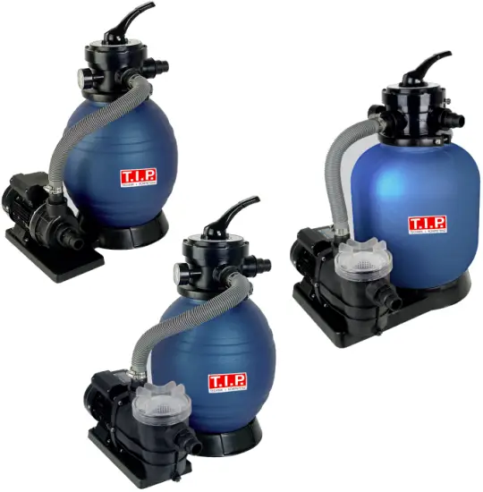
T I P SPF Series Pool Filter System Instruction Manual
Translation of the Original Operating Instructions
![]() Strictly ensure that you have read the use instructions before placing the pump in service!
Strictly ensure that you have read the use instructions before placing the pump in service!
Dear customer,
Congratulation for buying your new device from T.I.P.!
Like all our products, this one, too, was developed using the latest technological knowledge. The device was manufactured and assembled on the basis of state-of-the-art pump technology using most reliable electrical or electronic components which ensure a high level of quality and a long life of your new product.
Please read through these operating instructions carefully to make sure that you can fully benefit from all features.
Some explanatory illustrations can be found at the end of these operating instructions.
We hope you will enjoy your new device!
General safety information
Please read through these operating instructions carefully and make yourself conversant with the control elements and the proper use of this product. We shall not be liable in the case of damage caused as a result of the non-observance of instructions and provisions of the present operating instructions.
Any damage caused as a result of the non-observance of the instructions and regulations contained in the present operating instructions shall not be covered by the warranty terms. Please keep these operating instructions in a safe place and hand them on together with the device should you ever dispose of it.
With the contents of this manual unfamiliar people should not use this device.
The pump must not be used by children.
The pump may be used by persons with reduced physical, sensory or mental capabilities or lack of experience and / or knowledge if they have been supervised or instructed in the safe use of the equipment and have understood the resulting hazards.
Children are not allowed to play with the device. Keep the appliance and its cord out of reach of children.
The pump must not be used when people or animals are in the water.
The pump must be supplied through a residual current device (RCD) having a rated residual operating current not exceeding 30mA.
If the supply cord is damaged, it must be replaced by the manufacturer, its service agent or similarly qualified persons in order to avoid a hazard.
Notes and instructions with the following symbols require particular attention:
![]() Any non-observance of these instructions involves the danger of bodily harm to people and/or damage to property.
Any non-observance of these instructions involves the danger of bodily harm to people and/or damage to property.
![]() Any non-observance of this instruction bears the risk of an electrical shock which may cause damage to persons or property.
Any non-observance of this instruction bears the risk of an electrical shock which may cause damage to persons or property.
Check the product for transport damage. In case of damage, the retailer must immediately – be informed – but not later than the date of purchase within 8 days.
Technical data
| Model | SPF 180 | SPF 250 F | SPF 370 F |
| Mains voltage / frequency | 220-240 V~ / 50 Hz | 220-240 V~ / 50 Hz | 220-240 V~ / 50 Hz |
| Performance P1 / P2 | 250 Watt / 180 Watt | 400 Watt / 250 Watt | 550 Watt / 370 Watt |
| Protection class | IPX5 | IPX5 | IPX5 |
| Flow rate through sand filter | 4.500 l/h | 6.000 l/h | 7.000 l/h |
| Max. Flowrate pump (Q max ) 1) | 7.900 l/h | 10.000 l/h | 13.200 l/h |
| Max. pressure | 0,6 bar | 1,0 bar | 1,2 bar |
| Suction port / pressure port | 45,48 mm (1½“ female) | 45,48 mm (1½“ female) | 45,48 mm (1½“ female) |
| Hose connector | 32 mm (1¼“),38 mm (1½“) | 32 mm (1¼“),38 mm (1½”) | 32 mm (1¼“),38 mm (1½”) |
| Max. fluid temperature (T max) | 40° C | 40° C | 40° C |
| Min. fluid temperature (T min) | 5° C | 5° C | 5° C |
| Grain size of quartz sand | 0,5 to 0,8 mm0,7 to 1,2 mm | 0,5 to 0,8 mm und 0,7 to1,2 mm | 0,5 to 0,8 mm0,7 to 1,2 mm |
| Sand filling quantity2) | 13 kg | 13 kg | 25 kg |
| Length of power cord | 1,9 m | 1,9 m | 1,9 m |
| Type of power cord | H07RN-F 3 G 1,0 mm² | H07RN-F 3 G 1,0 mm² | H07RN-F 3 G 1,0 mm² |
| Weight of pump | 4 kg | 5 kg | 5,5 kg |
| Dimension of filter set | 50 x 35 x 64 cm | 50 x 50 x 64 cm | 50 x 50 x 68 cm |
| Total weight of filter set | 8 kg | 10,8 kg | 12,8 kg |
| Article No. | 30307 | 30308 | 30309 |
- The values were determined with free, unreduced in- and outlet.
- Quartz sand not included
Position and function
The pool filter set should be placed on a level concrete slab, very firm ground, or equivalent approximately 2 to 3 m from the pool edge. Ensure that the ground will not subside, preventing any strain from the attached plumbing. Protect the set from splash water and humidity. It should not be placed in an earth hole or directly on the grass ground.
Make sure, the inlet of the pump is placed at least 30 cm under the water level of the swimming pool.
Please note the pump shall be placed on a well-ventilated and dry location, which is protected
against floating and splash water and easy to reach for maintenance. The pump shall not be placed
into a too small chamber or compartment in order to avoid overheating.
![]() Make sure that all electric parts of the pump do not get in touch with water. Dangerous!
Make sure that all electric parts of the pump do not get in touch with water. Dangerous!
![]() The pump is not suited to discharge saltwater, feces, inflammable, etching, explosive or other
The pump is not suited to discharge saltwater, feces, inflammable, etching, explosive or other
hazardous liquids. Please observe the max. Temperature of the liquids to be discharged stated in the technical data.
Function of the sand filter set
Incoming water from the piping system is automatically directed by the 4 position valve to the top of the filter bed. As the water is pumped through the filter sand, dirt and debris are trapped by the filter bed, and filtered out. The filtered water is returned from the bottom of the filter tank, through the 4 position valve and back through the piping system.
Range of use
This swimming pool filter set is for cleaning of swimming pool water. This device is for the private use and not for industrial or commercial usage.
Do not store swimming pool disinfectant near the filter sets.
Prevent chemicals and vapors come with the filter set to touch and spoil the material.
Scope of delivery and optional accessories
This product includes:
A sand filter tank including base plate, 4-way valve, one pump, two bags with connection and installation accessories (see chapter 6 “Installation”), an instruction manual.
Check the contents for completeness. If possible, keep the packaging until the end of the warranty period. Dispose of packaging materials in an environmentally sound manner.
Depending on the application, additional accessories may be required (see chapter “How to order spare parts”).
Installation
General Installation Instructions
![]() During the entire process of installation, the device must not be connected to the electrical mains.
During the entire process of installation, the device must not be connected to the electrical mains.
![]() The pump and the entire port system must be protected against frost.
The pump and the entire port system must be protected against frost.
All connection lines have to be perfectly tight since leaking lines may affect the performance of the pump and cause considerable damage. If required, please use a suitable sealant to make the installation airtight.
Avoid when tightening screw excessive force that may cause damage.
When laying the connection pipes, you should make sure that the pump is not exposed to any form of
weight, vibration or tension. Moreover, the connection lines must not contain any kinks or an adverse slope.
Please observe the illustrations, too, which are contained as an attachment at the end of the present operating instructions. The numeric and other details included in brackets below refer to these illustrations.
Please observe the graphic figures in this manual. The numbers and other indications in brackets refer to the following graphic figures in this text.
Installation of sand filter
- Mount the pump to sand filter support by using bolts and nuts. (fig. 1)

- Install the drain plug assembly to sand tank as below pictures. (fig. 2)

- Press and turn the sand tank to mount it to sand filter support with correction direction (fig. 3).

- Insert the tube with filter basket inside the tank as above picture, then place the funnel on the tank’s mouth and pour the quartz sand into the tank (sand weight 13 kg). Please ensure no sand is falling into the tube. (fig. 4)

- Remove the funnel and clean the edge of the container opening carefully sand residues. To facilitate the start-up, it is recommended to fill the sand filter tank to ¾ with water. Then mount the 4- way valve and the filter gasket (O-ring, Fig. 5).

The connection is made with a clamping ring. The clamping ring is screwed to the clamping ring screw and clamping ring nut. - Connect the sand tank to pump with hose, hose clamps and hose adaptors. (fig. 6)

Please carefully note for the installation
- Make sure the filter is working under pressure, and using a pressure control valve when the systems using a booster pump.
- If the pump position is lower than the water level as recommended, it requires installing an isolation valve. It could stop the water return back for general care and maintenance.
- Reducing the connect adaptors and hose connecting bending as less as possible. Decreasing the water flow scrub, it could reach the maximum effective.
- Ensure solvents are not excessively applied to fittings as this could run into o-ring and cause damage of the sealing’s.
- Do not over tighten fittings or adapters.
- Installation of pump inlet and outlet hose
The pump is developed according to the latest technology. These preventive actions during installation will ensure a trouble-free operation for many years. Use a pump inlet hose with the same diameter as the suction port of the pump at least 40 mm (1½” female). The weight of the plumbing’s and fittings is to be independently supported and not carried by the pump.
The pump inlet must be installed under the water level of the pool, because the pump works with an intake water supply.
For easier maintenance and care, we recommend the installation of an isolation valve. The advantage is, that by closing the isolation valve no water runs out of the pool.
 fig. 7
- inlet from the pump (marked “pump”)
- outlet to the swimming pool (marked “pool”) for normal filter operation
- outlet for waste water (marked „waste“) for back wash
- pressure gauge
Make sure, there is sufficient in the sand filter tank before priming the pump
If the pump does not prime, please observe the notes in the section trouble shooting.
Make sure, all inlet and outlet valves are open, before priming the pump. Otherwise this could cause severe damage of the pump.
Fixed installation
![]() For fixed installation of the electrical connection, make sure the plug can be easily reached and is visible. For fixed installation the pump should be placed on a solid, horizontal surface.
For fixed installation of the electrical connection, make sure the plug can be easily reached and is visible. For fixed installation the pump should be placed on a solid, horizontal surface.
Please note:
![]()
- If the filter is installed below the water surface, a shut-off valve should be installed.
This prevents unnecessary water flow during maintenance.
Electrical connection
The unit is equipped with a mains connection cable and a mains plug. It must only be replaced by qualified staff to avoid any danger. Please do not use the mains connection cable to carry the pump, and do not use this cable to pull off the plug from the socket, either. Protect the mains connection cable and mains plug from heat, oil or sharp edges. Defect power cords must be replaced immediately.
![]() The values stated in the technical details have to correspond to the mains voltage.
The values stated in the technical details have to correspond to the mains voltage.
![]() The person responsible for the installation has to make sure that the electrical connection is earthed in compliance with the applicable standards.
The person responsible for the installation has to make sure that the electrical connection is earthed in compliance with the applicable standards.
![]() The electrical connection has to be equipped with a highly sensitive residual current circuit-breaker (FI switch): ∆ = 30 mA (DIN VDE 0100-739).
The electrical connection has to be equipped with a highly sensitive residual current circuit-breaker (FI switch): ∆ = 30 mA (DIN VDE 0100-739).
![]() If extension cables are used, their cross-section must not be smaller than that of rubber-sheathed cables of the H07RN-F (3 x 1.0 mm²) short code. The mains socket and the plug-and-socket elements have to be in splash-water-proof design.
If extension cables are used, their cross-section must not be smaller than that of rubber-sheathed cables of the H07RN-F (3 x 1.0 mm²) short code. The mains socket and the plug-and-socket elements have to be in splash-water-proof design.
![]() The electrical installation must be done in accordance with the safety regulation for swimming pools and in particular with standard HD 60364-7-702 and other local specifications regulations.
The electrical installation must be done in accordance with the safety regulation for swimming pools and in particular with standard HD 60364-7-702 and other local specifications regulations.
Putting into operation
![]() For the first operation it is recommended to fill the sand filter tank with water.
For the first operation it is recommended to fill the sand filter tank with water.
![]() Avoid any dry-running – operation of the pump without suction of water. This could cause an overheating of the pump and severe damage of the device. In addition to this, there then very hot water in the system, this can cause burning injuries and scalding. In case of an overheated pump pull out the power cord and let the system cool down. The floating ring seals can be damaged if the pump is running dry and should be replaced if this happened.
Avoid any dry-running – operation of the pump without suction of water. This could cause an overheating of the pump and severe damage of the device. In addition to this, there then very hot water in the system, this can cause burning injuries and scalding. In case of an overheated pump pull out the power cord and let the system cool down. The floating ring seals can be damaged if the pump is running dry and should be replaced if this happened.
![]() Do not expose the pump to rain or humidity. Avoid any dripping connectors. Do not place the pump in a wet or humid environment. Make sure the pump and the electrical plugs are located in an area, which is secured against flooding.
Do not expose the pump to rain or humidity. Avoid any dripping connectors. Do not place the pump in a wet or humid environment. Make sure the pump and the electrical plugs are located in an area, which is secured against flooding.
![]() The pump must not be operated, if the inlet valve is closed.
The pump must not be operated, if the inlet valve is closed.
![]() It is absolutely forbidden to touch with the hands into the openings of the pump, if the device is connected to the power supply.
It is absolutely forbidden to touch with the hands into the openings of the pump, if the device is connected to the power supply.
- Please inspect the pump visually prior to each use. This applies in particular to the mains connection line and the mains plug. Make sure that all screws are firmly tightened, and verify the perfect condition of all connections. A damaged pump must not be used. In any case of damage, the pump has to be inspected by qualified service staff.
- Each time the pump is put into operation, please make sure that the pump is set up securely and firmly standing.
- To put the unit into operation, please plug the mains plugs into a 230V AC socket. If the water level has reached or exceeded the cut-in level, the pump will start to run immediately.
- To stop the operation of the pump, please pull the mains plug off the socket.
- The electrical pumps of the T.I.P. SPF series are equipped with an integrated thermal motor protection feature. In the case of overload, the motor will switch off independently and on again after cooling down. For possible causes and their elimination, please refer to the “Maintenance and troubleshooting” section 8.
Please note for the first operation
To prevent unnecessary strain on piping system and valves always shut off pump before switching filter control 4 position valve positions.
All inlet and outlet valves must be open when starting the system. Otherwise this can cause severe damage of the pump.
- Press the top mount 4 position valve handle down and rotate to backwash position
- Prime and start the pump according to these instructions.
- Once water flow is steady out the waste line, run the pump for at least 2 minutes. The initial backwashing of the filer is recommended to remove any impurities of fine sand particles in the sand media.
- Turn pump off and set valve to rinse position. Start pump and operate until water in sight glass is clear – about ½ to 1 minute. Turn pump off, set valve to FILTER position and restart pump. Your filter is now operating in the normal filter mode, filtering particles from the pool water
![]() High suction lift or long suction hoses require additional time and reduce the performance of the pump. If the pump does not prime, repeat steps 1 and 2.
High suction lift or long suction hoses require additional time and reduce the performance of the pump. If the pump does not prime, repeat steps 1 and 2.
Note:
Regular maintenance of the pump and sand filter extends the life cycle of the pump and increases the efficiency.
If the water level to be dropped in the sand filter tank, you should fill up the tank again before recommissioning.
- Remove the translucent lid and fill the filter tank with water.
- Replace the lid ensuring the o-ring is correctly located and start the pump.
After you have done this allow a few minutes (maximum) running for the pump to start delivering water.
Functions of the 4-position valve of the sand filter:
Filter – Set valve in position filter for normal filter operation.
Backwash: for cleaning the filter. When filter pressure gauge raises 0.5 bar above start-up, a cleaning of the filter must be done:
Stop the pump, set valve to backwash. Start pump and backwash for approximately 2 minutes or less depending on dirt accumulation. Proceed to rinse.
Rinse After backwashing, with pump off, set valve to rinse. Start pump and operate for about 1 minute. This ensures that all dirty water from backwashing is rinsed out of the filter to waste, preventing possible return to the pool. Stop pump, set valve to FILTER and start pump for normal filtering.
Winter position – All valves are opened. In this position the pressure on the sealing’s is relieved.
Maintenance and care
![]() Prior to carrying out any maintenance work, the pump must be separated from the electrical mains. If you fail to separate the unit from mains, there is a risk of an inadvertent start of the pump.
Prior to carrying out any maintenance work, the pump must be separated from the electrical mains. If you fail to separate the unit from mains, there is a risk of an inadvertent start of the pump.
![]() We decline any liability for damage caused by inappropriate repair attempts. Any damage caused by inappropriate repair attempts will avoid all warranty claims.
We decline any liability for damage caused by inappropriate repair attempts. Any damage caused by inappropriate repair attempts will avoid all warranty claims.
Observing the conditions of use and the ranges of application of the present device will reduce the risk of possible operational malfunction and contribute to extend the lifetime of your unit. Sand and other abrasive matters contained in the liquid discharged will speed up the process of wearing and tearing and accelerate the drop in performance.
The user must ensure that maintenance is done from qualified persons, who have carefully read all instructions for installation and maintenance. In case the set is not used for a longer period, the pump and filter tank must be drained.
Frozen water inside the pump and filter tank can cause severe damage. Store the pump at a dry and frost-proof location. If the pump is operated again after a longer break, please ensure all sealing and und O-Rings are in good condition. Replace any defect or damaged sealing’s.
Check, if the motor shaft is moving freely before each new operation.
Check and clean the tube with filter basket (fig. 8, No. 5) in the sand filter tank (fig. 8) in regular intervals.
- Remove the lid with 4 position valve (fig. 8, No. 1) and take out the tube with filter basket (fig. 8, No. 5).
- Clean the filter basket with clear water.
- Do the assembly in reverse order. Check the sealing of the lid (fig. 8, No. 3). Replace damaged sealing’s immediately.
- Insert the tube with the filter basked (fig. 8, No. 5).
- Fill the sand filter tank again.
- Place the o-ring correctly.
- Pull the lid by hand.
- Switch on the pump again.
A regular check of the mechanical and electric parts is recommended:
- The accurate and right connection of adapters, hose and pipes and secured tightness of all screws.
- The correct condition of all electric connections and power cords.
- The vibration of the pump. In case of an excess high vibration, stop the pump immediately and contact your service partner or the manufacturer.
Troubleshooting / tips
In the case of malfunction, you should first of all check whether it was caused by an operating error or some other reason which cannot be attributed to a defect of the device – for instance a power failure.
The list below shows some possible malfunctions of the device, possible causes and tips on their elimination. All the measures referred to may only be carried out with the pump being separated from the electrical mains. If you yourself feel unable to eliminate any of these malfunctions, please contact the customer service department or your point of sales. Any repair beyond the scope specified below must only be performed by qualified staff. Please bear in mind that all warranty claims will become void in the case of damage caused by inappropriate repair attempts, and that we decline any liability for any ensuing damage.
| MALFUNCTION | POSSIBLE CAUSE | ELIMINATION |
|
|
|
|
|
|
|
|
|
|
|
|
|
|
Warranty
The present device was manufactured and inspected according to the latest methods. The seller warrants for faultless material and workmanship in accordance with the legal regulations of the country in which the device was purchased. The warranty period begins with the day of the purchase and is subject to the provisions below:
Within the period of warranty, all defects which are to be attributable to defective materials or manufacturing will be eliminated free of charge. Any complaints are to be reported immediately upon their detection.
The warranty claim becomes void in the case of interventions undertaken by the purchaser or by third parties. Damage resulting from improper handling or operation, incorrect setting-up or storage, inappropriate connection or installation or Acts of God or other external influences are excluded from warranty.
Parts being subject to wear and tear are excluded from warranty.
All parts were manufactured using maximum care and high-quality materials and are designed for a long lifecycle. It should be understood, however, that the wear and tear depends on the kind of use, the intensity of use and the internals of maintenance. Complying with the installation and maintenance information contained in the present operating instructions will therefore considerably contribute to a long lifecycle of these wearing parts.
In case of complaints, we reserve the option of repairing or replacing the defective parts or replace the entire device. Replaced parts will pass into our property.
Claims for liquidated damages are excluded unless they are caused by willful acts or negligence on the side of the manufacturer.
The warranty does not provide for any claims beyond those referred to above. The warranty claim has to be evidenced by the purchaser in the form of the submission of the sales receipt. The present warranty commitment is valid in the country in which the device was purchased.
Please note:
- Should your device fail to function properly, please verify first whether an operating error or another cause is present which cannot be attributed to a defect of the device.
- In case you have to take or send in your defective device for repair, please be sure to enclose the following documents:
- Sales receipt (sales slip).
- A description of the occurring defect (a description as accurate as possible will expedite the repair work).
- In case you have to take or send in your defective device for repair, please remove any attached parts which do not belong to the original condition of the device. If any attached parts of this kind should be missing upon the return of the device, we shall not be liable for them.
How to order spare parts
The fastest, most simple and cheapest way of ordering spare parts is through the internet. On our
www.tip-pumpen.de website you will find a convenient spare part shop where you can order spare parts with just a couple of clicks. In addition, this is also the place where we publish comprehensive information and valuable tips on our products and accessories, introduce new devices and present current trends and innovations in the range of pump technology. Original spare parts and accessory, which are authorized by the manufacturer, ensure a high degree of safety. The manufacturer of the pump is not liable for any damage or injuries which are caused by the usage of non-authorized spare parts and accessory.
Service
In the case of warranty claims or malfunction, please contact your point of sale.
A current operating manual is available as required as a PDF file via e-mail: service@tip-pumpen.de.
![]() For EC countries only
For EC countries only
Please do not dispose of electrical appliances in the regular domestic waste!
According to the European Directive 2012/19/EU regarding waste electrical and electronic equipment and the implementation of that directive into national law, electrical devices have to be collected separately and disposed of in an environmental-suitable manner after the end of their life cycle. Should you have any questions, please contact your local waste disposal company.
Appendix

Fig. 9
| Position | Item Number | DESCRIPTION SPF 180 AND SPF 250 F | Quantity |
| 1 | 72140 | 4-Way-Valve | 1 |
| 2 | 72141 | Clamping ring | 1 |
| 3 | 72142 | O-Ring | 1 |
| 4 | 72143 | Sand filter container | 1 |
| 5 | 72144 | Exhaust pipe with filter basket | 1 |
| 6 | 72145 | Drain filter | 1 |
| 7 | 72146 | Baseplate | 1 |
| 8 | 72147 | Screw M6 * 25 and nuts M6 | 4 |
| 9 | 72148 | O-Ring | 5 |
| 10 | 72149 | Hose connection | 5 |
| 11 | 72150 | Hose clamp | 2 |
| 12 | 72151 | 32 mm (1¼ “) * 35 cm connecting hose | 1 |
| 13 | 72152 | Pump SPF 180 (220 ~ 240V 50Hz) completely | 1 |
| 14 | 73052 | Pump SPF 250 F (220 ~ 240V 50Hz) completely | 1 |
| 15 | 72153 | Hopper | 1 |
| 16 | 72154 | Manometer | 1 |
| 17 | 72155 | Sealing plug with O-ring 47.8 mm (1½ “external thread) | 1 |

Fig. 10
| Position | Item Number | Description SPF 370 F | Quantity |
| 1 | 72140 | 4-Way-Valve | 1 |
| 2 | 72141 | Clamping ring | 1 |
| 3 | 72142 | O-Ring | 1 |
| 4 | 73053 | Sand filter container | 1 |
| 5 | 72144 | Exhaust pipe with filter basket | 1 |
| 6 | 72145 | Drain filter | 1 |
| 7 | 73054 | Baseplate | 1 |
| 8 | 72147 | Screw M6 * 25 and nuts M6 | 4 |
| 9 | 72148 | O-Ring | 5 |
| 10 | 72149 | Hose connection | 5 |
| 11 | 72150 | Hose clamp | 2 |
| 12 | 72151 | 32 mm (1¼ “) * 35 cm connecting hose | 1 |
| 14 | 73055 | Pump SPF 370 F (220 ~ 240V 50Hz) completely | 1 |
| 15 | 72153 | Hopper | 1 |
| 16 | 72154 | Manometer | 1 |
| 17 | 72155 | Sealing plug with O-ring 47.8 mm (1½ “external thread) | 1 |

Fig. 11
| Position | Item Number | PUMP SPF 180 | Quantity |
| 20 | 72156 | Pump housing | 1 |
| 21 | 72157 | Impeller | 1 |
| 22 | 72158 | O-Ring | 1 |
| 23 | 72159 | Mechanical seal | 1 |
| 24 | 72160 | Cover | 1 |
| 25 | 72161 | Motor SPF 180 | 1 |
| 26 | 72162 | M5 x 20 | 4 |

Fig. 12
| Position | Item Number | PUMP SPF 250 F AND SPF 370 F | Quantity |
| 20 | 73056 | Remove cover | 1 |
| 21 | 73057 | O-Ring | 1 |
| 22 | 73058 | Filter | 1 |
| 23 | 73059 | Pump housing | 1 |
| 24 | 73060 | O-Ring | 1 |
| 25 | 73061 | Diffuser | 1 |
| 26a | 73062 | Impeller SPF 250 F | 1 |
| 26b | 73063 | Impeller SPF 370 F | 1 |
| 27 | 73064 | O-Ring | 1 |
| 28 | 73065 | Mechanical seal | 1 |
| 29 | 73066 | Cover | 1 |
| 30 | 73067 | M6 x 25 | 6 |
| 31a | 73068 | Motor SPF 250 F | 1 |
| 31b | 73069 | Motor SPF 370 F | 1 |
| 32 | 73070 | M5 x 14 | 4 |
| 33 | 73071 | Nut M6 | 6 |
| 34 | 73072 | O-Ring | 1 |
| 35 | 73073 | Drain screw M6 | 1 |
Lieber T.I.P. Kunde,
Thank you for choosing our product!
Did everything work out and are you 100% satisfied with your purchase? Then please leave us an honest customer review on Amazon. Other customers will benefit from your experience and be happy with the product.
If you have any technical questions or problems during commissioning, please feel free to contact us at the following phone numbers:
EC declaration of conformity
We, T.I.P. Technische Industrie Produkte GmbH, Siemensstr. 17, D-74915 Waibstadt, declare in our sole responsibility that the products identified below comply with the basic requirements imposed by the EU directives specified below including all subsequent amendments:
2006/42/EC, 2014/30/EU, 2011/65/EU.
Art.:
Swimming pool filter set
SPF 180
SPF 180 E
SPF 250 F
SPF 370 F
applied standards
IEC 55014-1:2021
IEC 55014-2:2021
IEC 61000-3-2:2019 + A1:2021
61000-3-3:2013 + A1:2019
60335-1:2012 + A15:2021
IEC 60335-2-41:2021 + A11:2021
62233:2008
IEC 63000:2018
SPF 250 F – Informationen gemäß / informations according to EU 2019/1781:
1. Rated efficiency: 67.36% | 2. Level: IE2 | 3. Manufacturer: SPLASH POOL & SPA, INC. |
4. Motor model ID: CR1G229 | 5. Poles: 2 | 6. Rated kW: 0.26 | 7. Rated input Hz: 50 Hz | 8. Rated V: 230 | 9.
Rated rpm: 2850 | 10. Phases: 1 |11.
Operating conditions: (a) alt. above sea-level: <= 1.000m / (b) motor amb.-temp.: -10°C – 40°C / (c) water coolant temp.: n.a. / (d) max.
operating temp. 130°C / (e) pot. explosive atmospheres: not suitable
Documentation Representative:
T.I.P. Technische Industrie Produkte GmbH
Siemensstraße 17
D-74915 Waibstadt
Telefon: + 49 (0) 7263 / 91 25 0
Telefax + 49 (0) 7263 / 91 25 25
E-Mail: info@tip-pumpen.de
SERVICE HOTLINE
+49 (0) 7263 9125-0
Monday to Friday from 8:00 a.m. to 5:00 p.m.
Email: service@tip-pumpen.de
TECHNICIAN CONSULTATION HOURS
+49 (0) 7263 9125-50
Monday to Friday from 3:00 p.m. to 5:00 p.m.

Environmental labeling
T.I.P. Technische Industrie Produkte GmbH
Siemensstraße 17
D-74915 Waibstadt / Germany
Tel.: +49 (0) 7263 9125-0
Fax: +49 (0) 7263 9125-85
Website: http://www.tip-pumpen.de

Documents / Resources
 |
T I P SPF Series Pool Filter System [pdf] Instruction Manual SPF 180, SPF 250 F, SPF 370 F, SPF Series Pool Filter System, Pool Filter System, Filter System |