![]() TinyDash Compact and Powerful Display
TinyDash Compact and Powerful Display
User Manual TinyDash
TinyDash Compact and Powerful Display
This document is intended for use by a technical audience and describes a number of procedures that are potentially hazardous. Installations should be carried out by competent persons only.
Syvecs and the author accept no liability for any damage caused by the incorrect installation or configuration of the equipment.
Please Note that due to frequent firmware changes certain windows might not be the same as the manual illustrates.
If so please contact the Syvecs Tech Team for Assistance.
Support@Syvecs.com
Introduction
The TinyDash is a compact and powerful display designed to offer customers vital real me informa on from their vehicles electronics.
The palm sized unit has been designed with simplicity in mind and to ensure users a hassle free installa on process. It requires only one switched 12v supply along with a two wire CAN bus connec on.
Being specialists in OEM CAN data decoding, we have added many popular OEM data streams into the TinyDash so ware as well as a er-market ECU company data. This enables instant access to vehicle opera ng parameters via the 2.4 inch screen. A list of support vehicles / ECU’s can be found on the last page.
Two low current PWM outputs are present on the TinyDash and can be setup to do custom tasks via our SCAL so ware. Please note these outputs will only handle 1 amp of continuous current so mainly used for warning light or to trigger a relay.
Four analog inputs are also present on the TinyDash and have so ware selectable 3k pull-ups present to allow not only 0-5V ADC reading but 0-5v Thermistor sensors data. These are parcularly useful if you are I/O limited in your installa on and wish to send voltage or sensor data to your engine controller via CAN in another sec on of the vehicle. The custom CAN transmit and flexible CAN secons of our SCAL so ware make this really easy.
Specifications
Outputs
2 x PWM Outputs – 2Amp Peak (100ms) / 1Amp Continuous
1 x 5V Sensor Supply (400ma Max)
Inputs
3 Analogue/Thermistor Inputs (0-5V) with soware pull-up
Interfaces
USB C For Updates and Configuration 1 x CAN 2.0B, user programmable
Power Supply
6 to 26V ignition switched supply
Physical
Harwin Datamate Connector 78mm x 50mm x 20mm
Environmental
High-quality anodised CNC aluminium body and military spec wiring (Tyco Spec44) ensures a rigorous and long-term use.
Using this manual
This manual highlights important information, warnings or useful tricks with the following colours:
Text in ORANGE describes a step that may be required or information that is important for correct operation.
Text in RED are Warnings and must be followed when installing or operating the unit, failure to do so may damage the unit and will not be covered under warranty.
Letters highlighted and underlined in software instructions such as Device > Program are keyboard shortcuts. For example program the device by pressing keyboard leer D followed by letter P when using SCal.
As you become more familiar with these shortcuts, the Syvecs SCal becomes very fast to use.
Pin Connections
 Looking into back of header, loom side
Mating connector PN: M80-4131098
Pin PN: M80-2060005
Pin Schedule
| Description | Pin Number | Function | Wire Colour |
| 12V | 1 | Switched 12V | Red |
| CANL | 2 | CAN Low | Yellow |
| CANH | 3 | CAN High | White |
| GROUND | 4 | Ground | Black |
| AN1 | 5 | 0-5v Analogue Input | Green |
| AN2 | 6 | 0-5v Analogue Input | Green |
| AN3 | 7 | 0-5v Analogue Input | Green |
| 5v Out | 8 | 5v Sensor Supply | Grey |
| LSO1 | 9 | Low Side Output | Pink |
| LSO2 | 10 | Low Side Output | Purple |
General Connections
Connecting Power/Ground
The TinyDash unit needs a single ignition 12v supply and single ground connection, as the unit does not consume much current a wire gauge of AWG24 or less can be used.
Warning: The unit must be powered from a fused source, 2A is sensible rating.
| Pin Number | Function | Notes |
| 1 | VBAT | Use a fused Switched feed. |
| 4 | Power Ground | Ground for Power and Sensor Signal |
Input Connections
Voltage Inputs – AN
Four Analogue Inputs are available on the TinyDash. These are just 0-5v analogue inputs and cannot support frequency waveforms.
They are designed for sensors like pressure transducers, thermistors, switches or position sensors.
All of the inputs have an optional 3k Pull up, which allows them to be used for thermistor sensors as well.
Wiring Guidance
All sensors use the power ground as the sensor ground. The sensor signal output can then be connected to any one of the three AN inputs.
Pin Schedule
| Pin Number | Function | Notes |
| 4 | Ground | May be shared with multiple sensors |
| 5 | AN1 Input | Any AN Input can be used |
Low Side Outputs
There are two low side outputs available on the TinyDash. They support 2 amp peak/1 amp continuous loads. They are suitable for driving relays and most boost solenoids.
Wiring Guidance
We recommend that each device being switched has its own 1 Amp fuse. This is to protect the low side drivers from damage due to excess current.
| Pin Number | Function | Notes |
| 9 | LSO1 | Low Side Output |
Calibration Switch / Cal Up / Down Switch
The TinyDash allows users to have a physical calibration switch wired to the device or virtual switch setup via CAN.
A physical switch can be done in multiple ways, first method is using the Syvecs 12Way rotary switch –https://www.syvecs.com/product/calibration-switch/
Second method is with a resistor chain up and Down switch setup which allows calibrators to set a low and high voltage threshold for each switch position.
Third method is via a single Cal Up Switch which cycles through all the positions and resets at a set Cal position back to 1.
Physical switches need to be assigned in the I/O configuration – Pin assignments.
Virtual switch setup via the OEM Preset CAN receive or via the Generic CAN receive strategy.
The TinyDash can also transmit the current Cal Selection position via CAN bus to other units like our engine control units. This saves inputs on the ECU and also additional wiring.
Pin Schedule
| Pin Number | Function | Notes |
| 4 | Ground | May be shared with multiple sensors |
| 7 | AN3 | Any AN input is supported |
The Syvecs 12 position calibration switch is set in Scal by settng the voltage thresholds for each position in the below map.
CalSelect will then update when the voltage is greater then set in the corresponding cell.
Note: If using a syvecs supplied Cal Switch you must have the Input Pull-up enabled.
Gear Position Setup
Gear position can be displayed on any Layout but its best to be viewed on Layout 7 which display the gear across the whole screen in a portrait position.
Note: the orientation of this can be flipped in the LCD Setup area of Scal.
There is multiple ways the gear can be picked up with the TinyDash, these are listed below:
Preset CAN Receive – If the OEM or Aftermarket ECU has the ability to transmit Gear on the CANbus it will be picked up a displayed.
 Generic CAN Receive – Calibrators can setup in Scal to receive the gear via a custom CAN RX setup
Gear Barrel / Position Sensor – Most Sequential gearboxes will come fitted with a gear posion sensor that outputs a voltage for each barrel position. In Scal the calibrator can assign the voltage for each gear position. Gear from wheel speeds – If VehicleSpeed and Rpm are being picked up by the TinyDash then calibrators can enable the map Gear position from wheel speed. This calculates gear from DriveRao (Rpm/Speed). Settng a drive ratio amount for each gear below then allows the gear to be decoded.

CanBus Communications
Common Area Network Bus (CAN Bus) is a widely used data interface common used in many cars and a ermarket accessories, such as Data loggers and Dashes. The TinyDash as default has 1 x CAN bus interface and this does not have 120ohm termination resistor present.
There are two ways of interfacing to the TinyDash.
- Hard wired directly to the vehicle/ECU CANbus (best option)
- Connect to the ODBII diagnostic port.
ODBII Connections
The TinyDash controller supports the OBD2 Data receive protocol allowing users to retrieve data via the OEM ECU OBD2 protocol making installation very straigh orward. (please note: Not ever manufacture supports the SAE J1979 protocol we use)
Example Schematic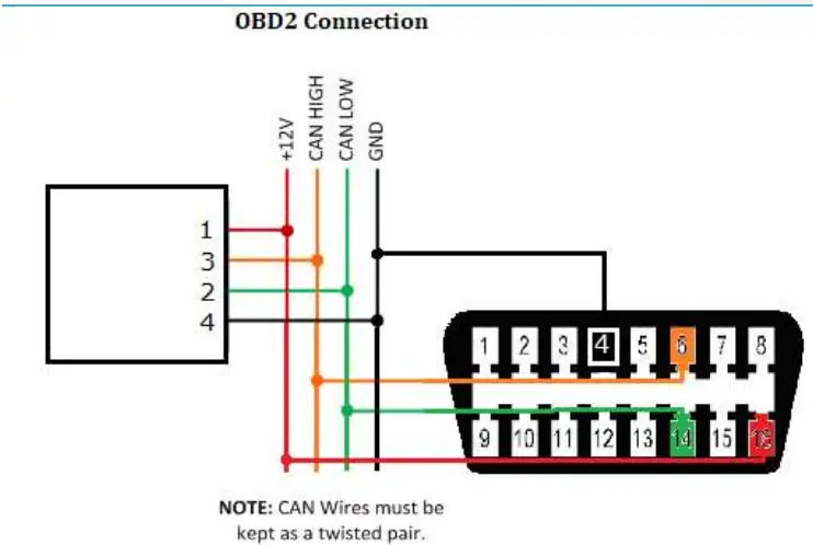
The OBD2 CAN wires need to be connected or as shown above and connected to CAN1 on the TinyDash module. Configuration is explained in the software section of this manual.
Direct CAN connection
TinyDash supports direct CAN connection to the vehicle or ECU data bus. This is a very powerful way of getting very fast real time vehicle running data. At the end of this manual is the list of supported OEM vehicles / Aftermarket Ecu’s which Syvecs support and it’s expanding all the time. Please Note: OEM Vehicle don’t all have the power-train CAN available at the OBD2 connect, users may need to connect on the CAN at the ECU location.
If the vehicle/Ecu you wish to connect to is not present then Syvecs also have a generic receive section for allowing calibrators to set a custom CAN receive setup.
Connecting the CAN network on your car needs to be done at the ECU location to ensure the powertrain CAN messages are present. T into the CAN wires and run them to the TinyDash.
No Termination Resistor is present on the TinyDash
Generic Can Receive
The generic CAN receive section allows for calibrators to setup the items they wish to display on the TinyDash by setting the Identifier, Start Bit, Length, and scaling.
The easier way to setup the Generic CAN is to create a worksheet and add in all the maps like below to make each CANRX* maps line up.
Above you can see the RPM is setup to be received from CAN ID 0x600, data is not Litile Endian, value is signed, scaling is 1.00 and is being picked up from start bit 0 with a length of 16 bits.
More info can be found on www.youtube.com/SyvecsHelp. Search for Generic Can Receive.
Please note: Any Item which is assigned in Pin Assignments will take its data from the Pin assignment and ignore the Generic CAN Rx data.
Example Wiring
 Pin 1 – 12v
Pin 3 – CAN H
Pin 4 – Ground
Pin 5 – Calibration Switch
Pin 10 – Boost Solenoid
PC Connection – SCAL
In order for the TinyDash to work it must have a valid calibration present in the device and when shipping from the factory no calibration is loaded to ensure calibrator’s setup the configuration to suit the installation.
A USB C port is found on the back of the TinyDash which is used for calibration changes on the device.
The S-Suite software can be downloaded from below.
https://www.syvecs.com/software/
Aer running the SSuite installer, open SCal and click Device > Connect. You will be asked “How do you wish to access this device”.
Click OK. Next you can load a calibration if you have one saved from a previous installation or program defaults if new installaon.
  The TinyDash will now connect. This status will be displayed in on the top right hand corner of SCal. A green indicator and Connected will be displayed.
 TIP When navigating within SCal you will note that some configuration settings are in blue and others green. All green settings take effect immediately, and do not require programming. Settings highlighted in blue need to be programmed before the changes take effect.
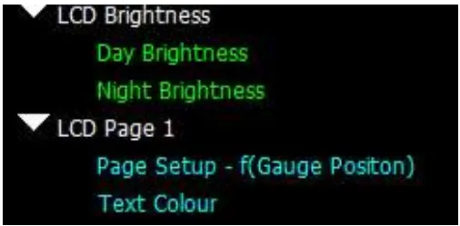 Calibrators now have the ability to setup the TinyDash live.
Press F1 for help on any map and remember that Calibration names highlights in Green are adjustable Live and changes are immediate. Blue Maps require programming (Device > Program) to take effect.
TinyDash Calibration
OBD2 Setup
The TinyDash controller supports the OBD2 Data receive protocol, allowing users to grab item data if it’s present on the OEM ECU OBD2 protocol making the installation even simpler.
OBD2 Supports: Rpm, Tps, Torque Actual, Torque Demand, Maf1, Map1, ACT , ECT, Lam1, Speed Select the input they wish to assign OBD2 data on and then select the OBDII: Item best suited.
Example: Air Charge Temp – OBDII ACT
Users need to Device – Program the controller after for the setting to be applied 
Mulple items can be assigned at the same time Layout Setup
Mulple layouts are available on the TinyDash and each layout can also have different data sets based on the calibration switch position. Under each Layout area is a setup map which allows users to input the items they wish to display. 4 layout sets are available meaning a layout style can display 6 different sets of items which are selectable under Calibraon Switch – Layout Control
  Users can also adjust the following in the LCD Setup area:
– Background Colour
– Text Colour
– Box Colour
– Orientation
– Brightness Layouts Available
 Alarms
Many Alarms can be set on the TinyDash unit, When an alarm is active it will bring up a red warning on the LCD Panel and also set a warning in Scal – AlarmActive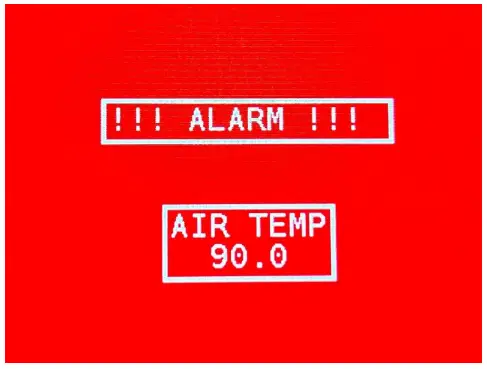 Custom alarms are easily configurable from the Alarm menu, for an alarm to trigger it must either be above a configurable maximum threshold, or under a minimum threshold.
 Alarms active RPM threshold allows you to turn off all alarms beneath a configured RPM limit. For example set that to 100RPM and the alarms will stop if the engine comes to a stop.
Where a minimum and maximum threshold exists such as the battery, the alarm will sound if it goes outside of either of those thresholds
The duration of the alarm is configured in “Alarm Hold Duration”, and this sets the time the Alarm warning page is active for.
Aer this time has passed another timer starts to set when the alarm page will display again. This can be adjusted in “Alarm Hold Off Duration” Note:
Note:
The Alarm page will only be displayed once if the item which is in alarm is present on the layout, are which point the item will change to Red on the screen to warn the user
Layout5 will not display an Alarm
Input – Sensor Setup
The Tinydash has three 0-5v inputs available and these can be selected in the I/O Configuration – Pin Assignments  Once assigned the calibrator can head to the sensors area to setup the input assigned.
 Input Type Select – Allows either a 5V or Thermistor to be selected. When thermistor is selected a 3K pull up resistor is enabled on the Input.
Input High Voltage Error Threshold – Sets the high voltage level for which the TinyDash will class the input in Error
Input Low Voltage Error Threshold – Sets the low voltage level for which the TinyDash will class the input in Error
Default Sensor Reading – When the input is in Error the value in this map will applied on the Item
Filter Constant – Amount of recursive filtering to be applied to the Signal, higher the value = more filtering
Linearisaon – Sets the input voltage to sensor units applied on the item
Output Testing
The TinyDash outputs can be tested live with our Syvecs – Scal program and information on connecting to the unit can be found in the PC Connection section of the manual. After connecting to the unit via USB, users will see an area at the bottom of the calibration tree called output testing.

Here users are able to test the functions of each output by itself without the need for any master/slave CAN communication.
NOTE: / Low Side Output Frequency maps must be set and programmed onto the device for the output tesng logic of these outputs to apply. You cannot change these maps when Output Test Mode Enable is enabled.
Remember that Calibration names highlights in Green are adjustable Live and changes are immediate. Blue Maps require programming (Device > Program) to take effect.
Set a frequency you wish the outputs to be driven at in LowSide Output Frequency. Device – Program for it to be saved. Then enable Output Test Mode Enable map.
Now you can then set a duty for each output to be driven in Low Side Output Test Duty, these maps can be adjusted live.
Strategy Help
All the strategies/maps on the TinyDash controller have help text available for them. This is shown by pressing F1 on the keyboard when in Scal when a calibration is open. 
Supported CAN Streams
The following OEM CAN streams are supported, but check the Syvecs Forum for TinyDash firmware updates as more cars will be added.
| RPM | MAP | TPS | PPS | (Driven Sport Mode) | Torque Actual | Torque Demand | ACT | ECT | EOT | Gear | BrakeP | Speed | LatG | LongG | |
| Audi Mk2 TTRS / RS3 | |||||||||||||||
| Audi Mk3 TTRS / RS3 / S3 | |||||||||||||||
| Audi R8 Gen1 | |||||||||||||||
| Audi R8 Gen2 | |||||||||||||||
| BMW E46 | |||||||||||||||
| BMW E92 | |||||||||||||||
| Corvette Z06 | |||||||||||||||
| Evo X | |||||||||||||||
| ECUMASTER | |||||||||||||||
| Honda FD2/FN2 | |||||||||||||||
| Honda FK2/FK8 | |||||||||||||||
| Infiniti Q60 | |||||||||||||||
| Jeep 2022 | |||||||||||||||
| Lamborghini LP520 | |||||||||||||||
| Lamborghini LP560 | |||||||||||||||
| Lamborghini Huracan | |||||||||||||||
| Lamborghini Aventador | |||||||||||||||
| LandRover Defender 90 110 | |||||||||||||||
| LINKECU | |||||||||||||||
| Mclaren12c,650,675,570,600, 720,765,P1 |
|||||||||||||||
| Mercedes Gen1 E55 C63 | |||||||||||||||
| Mercedes Gen2 C63 SLS | |||||||||||||||
| MoTeC M1 | |||||||||||||||
| Nissan 370Z | |||||||||||||||
| Nissan Patrol Y61 | |||||||||||||||
| Nissan Patrol Y62 | |||||||||||||||
| Nissan R35GTR | |||||||||||||||
| Porsche 991 / 981 / GTS /GT2RS / GT3 | |||||||||||||||
| Porsche 996 | |||||||||||||||
| Porsche 997/987 | |||||||||||||||
| Simos 18 | |||||||||||||||
| Subura Impreza My15+ | |||||||||||||||
| Suzuki 2013+ | |||||||||||||||
| Syvecs Ecu’s | |||||||||||||||
| Toyota Yaris Gr | |||||||||||||||
| Toyota LandCruiser/Lexus LX570 | |||||||||||||||
| Toyota GT86 /BRZ | |||||||||||||||
| VAG Me7 | |||||||||||||||
| VAG Me9 | |||||||||||||||
| VAG MED17 | |||||||||||||||
| VW Golf Mk5/6 Seat TFSI/TSI, AudiTSI/TFSI | |||||||||||||||
| VW Golf Mk7 MQB Seat MQB AudiMQB | |||||||||||||||
| Yamaha YXZ |
The following After-market ECU CAN streams are supported, but check the Syvecs Forum for TinyDash firmware updates as more Ecus will be added
| RPM | MAP | TPS | PPS | (Driven Sport Mode) |
Torque Actual | Torque Demand | ACT | ECT | EOT | Gear | Brake P | Speed | LatG | LongG | |
| ECUMASTER | |||||||||||||||
| LINKECU | |||||||||||||||
| MoTeC M1 | |||||||||||||||
| Syvecs Ecu’s |
![]()
Documents / Resources
 |
Syvecs TinyDash Compact and Powerful Display [pdf] User Manual SYV-TINYDASH, TinyDash Compact and Powerful Display, TinyDash, Compact and Powerful Display, Powerful Display |


