![]()
User Manual
DS-DMX23
Important: Read all instructions prior to installation.
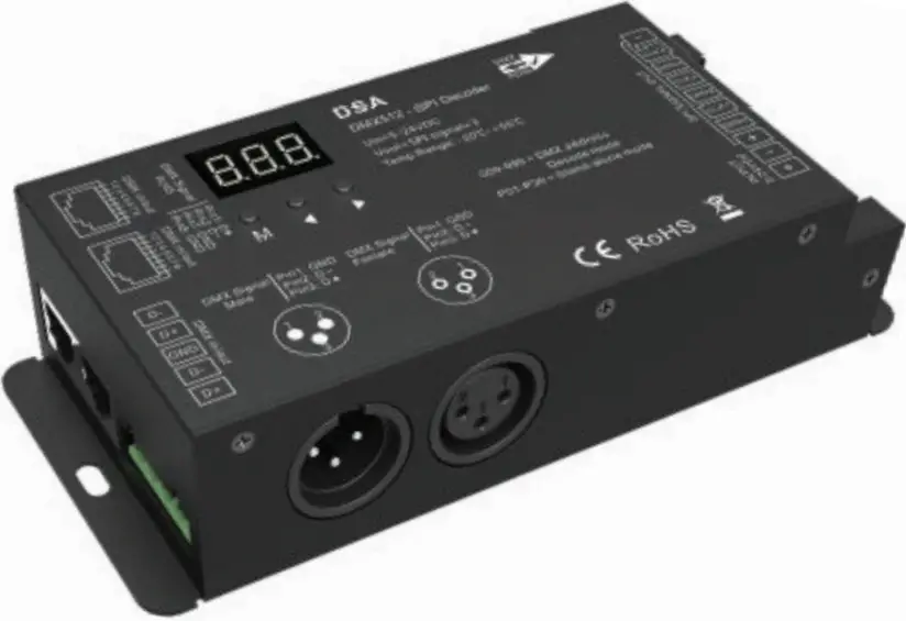
DMX512 to SPI Decoder/Controller
Safety and Notes
- The product should be installed and serviced in accordance with applicable national, state, and local building and electrical codes.
- To reduce the risk of electric shock, ensure that the power source and circuit breakers are switched off before performing any installation or wiring procedures.
- Strips controlled by data input only (same DATA and CLK output) can connect up to six strips.
- Strips controlled by data and clock input (separate DATA and CLK output) can connect up to three strips.
Check the product label for specific electrical specifications related to installation Improper installation will void the warranty.
Compatible IC Settings
| • D705 | • LPD8806 | • TLS3001 | • TM1812 | • UCS1909 | • UCS6909 | • WS2801 |
| • GW6205 | • MBI6120 | • TLS3002 | • TM1814B | • UCS1912 | • UCS6912 | • WS2803 |
| • LPD1101 | • P9813 | • TM1803 | • TM1829 | • UCS2903 | • UCS8904B | |
| • LPD6803 | • SK6812 | • TM1804 | • TM1914A | • UCS2909 | • WS2811 | |
| • LPD8803 | • SK9822 | • TM1809 | • UCS1903 | • UCS2912 | • WS2812 |
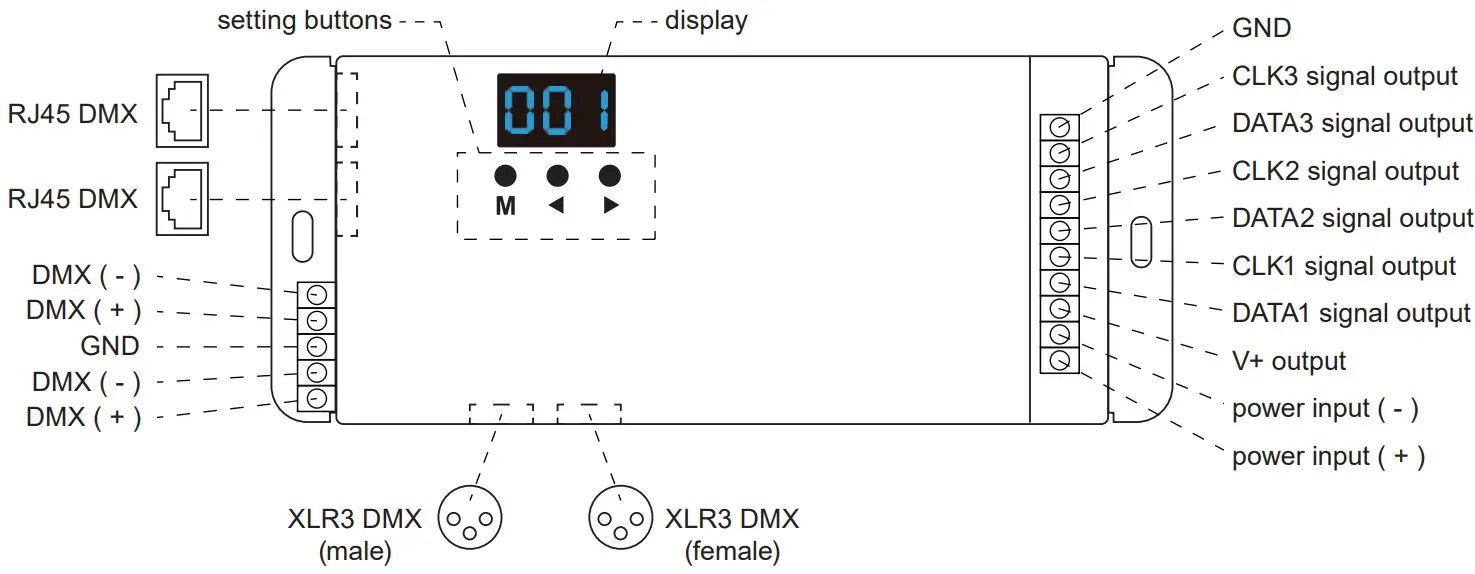
Controller Layout
Restore Factory Default Parameters
- Hold ◄ and ► button simultaneously for 2 seconds to display “RES”.
IC Type, RGB Order, and Pixel Length Settings
Note: IC type, RGB order, and pixel length of the intended LED strip(s) are required to complete this process.
- Hold M and ◄ buttons to enter programming mode. IC type, RGB order, pixel length, and automatic blank screen settings can be cycled through using the M button.
- Press ◄ or ► button to change the value of each setting.
- Once settings are set, hold the M key for 2 seconds or allow the controller to timeout after 10 seconds to exit programming mode.
 IC type
| No. | IC Type |
Output Signal |
| C11 | TM1803 | DATA |
| C12 | TM1809, TM1804, TM1812, UCS1903, UCS1909, UCS1912, UCS2903, UCS2909, UCS2912, WS2811, WS2812 | DATA |
| C13 | TM1829 | DATA |
| C14 | TLS3001, TLS3002 | DATA |
| C15 | GW6205 | DATA |
| C16M | B16120 | DATA |
| C17 | TM1814(RGBW) | DATA |
| C18 | SK6812(RGBW) | DATA |
| C19U | CS8904B | DATA |
| C21 | LPD6803, LPD1101, D705, UCS6909, UCS6912 | DATA, CLK |
| C22 | LPD8803, LPD8806 | DATA, CLK |
| C23 | WS2801, WS2803 | DATA, CLK |
| C24 | P9813 | DATA, CLK |
| C25S | K9822D | DATA, CLK |
| C31 | TM1914A | DATA |
 RGB order
| RGB Order Setting |
RGB Order |
| 0-1 | RGB |
| 0-2 | RBG |
| 0-3 | GRB |
| 0-4 | GBR |
| 0-5 | BRG |
| 0-6 | BGR |
![]() pixel length
pixel length
Pixel length value range is 008–900.
 disable automatic blank
Automatic blank screen settings can be toggled between enabling “bon” or disabling “boF”.
DMX Decode Mode
- Press the M button to cycle through settings and enter DMX decode settings. When on the correct setting, the display will show 001–999 displaying the current DMX decode setting.
- Press ◄ or ► button to change DMX decode start address.
- Hold M button for 2 seconds to enter setup for decode number and number of pixels. Once in this menu, press the M button to switch between the two settings. Press ◄ or ► button to change value.
-decode number (displays “dno”): DMX decode channel number, the range is 003–600.
-a number of pixels (displays “Pno”): Each 3 DMX channel adjustment sets control length. - Once settings are set, hold the M key for 2 seconds or allow the controller to timeout after 10 seconds to exit programming mode.
Standalone Mode
Standalone modes can only be used when the DMX signal is disconnected or lost.
- Press the M button to cycle through settings and enter standalone RGB mode. When on the correct setting, the display will show P01–P32, indicating the current setting.
- Press ◄ or ► button to change dynamic mode number (P01–P32).
- Each mode can adjust speed and brightness. Once the desired mode is selected, hold the M button for 2 seconds to enter speed and brightness settings.
- Press the M button to switch between speed and brightness. Press ◄ or ► button to select a setting value.
-Speed: 1–10 level speed (S-1–S-9, S-F for speed 10).
-Brightness: 1–10 level brightness (b-1, b-9, b-F). - Once settings are set, hold the M key for 2 seconds or allow the controller to timeout after 10 seconds to exit programming mode.
Standalone Modes
| No. | Name | No. | Name | No. |
Name |
| P01 | Red Race White Ground | P12 | Blue White Chase | P23 | Purple Float |
| P02 | Green Race White Ground | P13 | Green Cyan Chase | P24 | RGBW Float |
| P03 | Blue Race White Ground | P14 | RGB Chase | P25 | Red Yellow Float |
| P04 | Yellow Race Blue Ground | P15 | 7-color Chase | P26 | Green Cyan Float |
| P05 | Cyan Race Blue Ground | P16 | Blue Meteor | P27 | Blue Purple Float |
| P06 | Purple Race Blue Ground | P17 | Purple Meteor | P28 | Blue White Float |
| P07 | 7 Color Multi-Race | P18 | White Meteor | P29 | 6 Color Float |
| P08 | 7 Color Race Close + Open | P19 | 7 Color Meteor | P30 | 6 Color Smooth Sectionally |
| P09 | 7 Color Multi-Race Close + Open | P20 | Red Float | P31 | 7 Color Jump Sectionally |
| P10 | 7 Color Scan Close + Open | P21 | Green Float | P32 | 7 Color Strobe Sectionally |
| P11 | 7 Color Multi Scan Close + Open | P22 | Blue Float |
Pairing Optional RF Remote
In addition to using the built-in controls, this controller can be paired with a remote (DS-RT09).
To pair the remote, hold M and ► buttons for 2 seconds at which point the display will show “RLS”. Within 5 seconds, press the ON/OFF button on the remote, at which point the display will show “RLO” meaning the remote has been successfully paired. Hold the M key for 2 seconds or allow the system to timeout in 10 seconds to exit pairing. The maximum communication range is 98.4 ft (30 m) from the controller. Hold M and ► buttons for 5 seconds to unpair all remotes from the controller. Once the remote is paired, you can hold the upper mode (mode plus) button for two seconds to unlock preprogrammed standalone modes.
Remote Layout and Functions
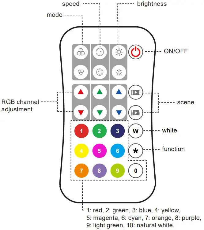
Mode
Once setup is complete (see page 3) press to cycle between preprogrammed modes.
Hold the upper mode (mode plus) button for two seconds to run the mode cycle demo setting. Hold the lower mode (mode minus) button for two seconds to return to and run mode 1.
Speed
Press to adjust the speed of the selected preprogrammed mode. Hold the upper speed (speed plus) button for two seconds to select the fastest speed. Hold the lower speed
(speed minus) button for two seconds to select the slowest speed.
Brightness
Press to adjust brightness in ten percent increments. Hold for continuous 256 level adjustment.
RGB
Press to adjust in ten percent increments. Hold for continuous 256 level adjustment.
White
Press to turn white (RGB mix) on/off. Hold for continuous 256 level adjustment.
Scene
Each scene button can save one setting. The setting is saved by holding the scene button for two seconds. Press the scene button after saving settings to recall those settings.
Setting Adjustment
Strip Length (Pixel Number) Setting
Strip length, or pixel number, can be set up to 900 pixels. Begin by pressing the function button (*), then entering the number of pixels with the number buttons, then pressing the function (*) button again.
IC Type Setting
IC type can be set by pressing the function button (*), then entering the two-digit code corresponding with the correct IC type using the number pad, then pressing the function (*) button again. Consult the list below for the code for each IC type.
| Code |
IC Type |
| 11 | TM1803 |
| 12 | TM1809, TM1804, TM1812, UCS1903, UCS1909, UCS1912, UCS2903, UCS2909, UCS2912, WS2811, WS2812 |
| 13 | TM1829 |
| 14 | TLS3001, TLS3002 |
| 15 | GW6205 |
| 16 | MBI6120 |
| 17 | TM1814B(RGBW) |
| 18 | SK6812(RGBW) |
| 19 | UCS8904B(RGBW) |
| 21 | LPD6803, LPD1101, D705, UCS6909, UCS6912 |
| 22 | LPD8803, LPD8806 |
| 23 | WS2801, WS2803 |
| 24 | P9813 |
| 25 | SK9822 |
| 31 | TM1914A |
RGB Order
RGB order can be set by pressing the function button (*), then entering the one-digit code corresponding with the correct RGB order using with the number pad, then pressing
the function (*) button again.
|
Code |
RGB Order |
| 1 | RGB |
| 2 | RBG |
| 3 | GRB |
| 4 | GBR |
| 5 | BRG |
| 6 | BGR |
Rev Date: V3 03/18/2021
4400 Earth City Expy, St. Louis, MO 63045
866-590-3533 superbrightleds.com

Documents / Resources
 |
SUPER BRIGHT LEDS DS-DMX23 DMX512 to SPI Decoder/Controller [pdf] User Manual DS-DMX23, DMX512 to SPI Decoder, DMX512 to SPI Controller |