
Spectrum DOCSIS 3.1 Advanced Voice Modem User Guide
Spectrum D3.1 eMTA
DOCSIS 3.1 Advanced Voice Modem
User Guide – Version 8
October 15, 2024
Understanding Device Connections
Rear Panel:
Voice 1-2: Use to connect analog telephones to the device. Telephone service must be enabled by the service provider.
Cable: Use to connect to the coaxial cable from your Internet service provider.
Ethernet (Internet): Connects to an Ethernet-enabled device such as a wireless router using an RJ45 Ethernet cable.
Power: Connects to the power adapter. Plug the other end into the wall power outlet.
Battery: Use to connect to an optional external battery. The battery connection is for voice services.

Installing Modem
- Connect the coaxial cable (not supplied) to the Cable connector on the rear panel of the eMTA and connect the other end to the cable wall outlet. Do not bend or over tighten the cables, as this may strain the connector and cause damage. To connect an eMTA and a television to the same wall outlet, you must use a cable line splitter (not included).
- Connect the Ethernet cable (supplied) to the Ethernet (Internet) port on the back panel of the eMTA and connect the other end to an Ethernet port on a wireless router (or other Ethernet-enabled device).
- Connect an RJ-11 phone cable (not supplied) to the Voice 1 or 2 port on the modem (when provisioned for voice service as specified by the service provider), and connect the other end to the phone port of the telephone. If voice service is not provisioned through the service provider, telephone service is not available.
- Connect the power adapter (supplied) to the Power port on the modem. Connect the other end to a power outlet.
Installation Diagram

Device Wall Mount Instructions
You can mount the modem on a wall using the 2 mounting brackets on the side of the device. Two round or pan head screws are recommended. See the figure below for measurements.

To mount the device on a wall:
1. Install the 2 screws horizontally on the wall 140 mm (5.51 inches) apart.

Note: The screws should protrude from the wall so you can fit the device between the head of the screws and the wall. If you install the screws in drywall, use hollow wall anchors to ensure the unit does not pull away from the wall due to prolonged strain from the cable and power connectors.
2. Mount the device on the wall.
Note to CATV System Installer:
This reminder is provided to call the CATV systems installer’s attention to section 820-93 of the National Electric Code, which provides guidelines for proper grounding and in particular, specify that the Coaxial cable shield shall be connected to grounding system of the building, as close to the point of cable entry as practical.
Reseting the Modem
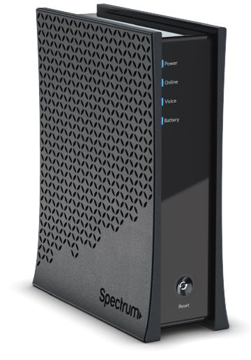
Front Panel:
Reset: Use the reset button to either reboot (power cycle) the modem or reset the device to factory default settings. When the reset button is pressed and held for 4 to 10 seconds, the device will reboot (power cycle). If the reset button is pressed and held for 10 seconds or more, the Spectrum eMTA will reset to factory default settings. Refer to the LED Behavior table on page 5 for the reset button LED behavior.

Note: When the device is in a state that suggests a power cycle (the button icon and the surrounding ring are lit), a factory reset cannot be performed. The user must power cycle the device, then perform a factory reset.
LED Behavior

Basic Modem Info

Product Specifications
Interfaces & Standards
- Cable: F-Connector, female
- Models: E31N2V1, E31T2V1, E31U2V1
- LAN: One 10/100/1000 Mbps RJ-45 port
- Models: EN2251, ET2251, EU2251, ES2251
- LAN: One 10/100/2.5 Gbps RJ-45 port
- Telephony: 2 RJ-11 ports
- PacketCable 1.5 (NCS) or 2.0 (IMS/SIP) ccompatible
- DOCSIS 3.1 certified
Downstream*
- Frequency Range: 258MHz-1218MHz
- Capture Bandwidth: 1.218GHz
- Modulation: 64 or 256 QAM and OFDM: up to 4096 QAM
- Maximum DOCSIS 3.1 Data Rate: 2 x 192MHz OFDM channels provide capacity up to 5Gbps
- Maximum DOCSIS 3.0 Data Rate: 32 downstream channels provide speeds up to 1372Mbps
- Symbol Rate: 5361 Ksps
- RF (cable) Input Power:
- -15 to +15dBmV (64/256 QAM)
- -6 to +15dBmV (4096 QAM)
- Input Impedance: 75 Ω
Upstream*
- Frequency Range: 5MHz ~ 42MHz/85MHz switchable
- Modulation: QPSK or 8/16/32/64/128 QAM and OFDMA: up to 4096 QAM
- Maximum DOCSIS 3.1 Data Rate: 2 x 96MHz OFDMA channels provide capacity up to 2Gbps
- Maximum DOCSIS 3.0 Data Rate: 8 upstream channels provide speeds up to 246Mbps
- Symbol Rate: 160, 320, 640, 1280, 2560, 5120 Ksps
- RF (cable) Output Power:
- A-TDMA/S-CDMA (one channel): +65dBmV
- OFDMA: +65dBmV
Security
• DOS (denial of service) attack protection
Regulatory
• UL/FCC Class B, Energy Star Certified
Voice
• PacketCable 1.5 (NCS) or 2.0 (IMS/SIP) compatible
• Line Voltage On-hook: -48 Volts, Loop Current: 20mA/41mA, Ring Capability: 2K ft., 5REN, Hook
State: Signaling Loop Start
- DTMF Tone Detection, T.38 Fax Relay (G.711), Echo Cancellation (G.168) / Silence Suppression, Voice Active Detection and Comfort Noise Generation
- G.722 codec, WB SLIC
Physical and Environmental
- Dimensions: 70.8mm, 2.8 inches (W), 215mm, 8.46 inches (H), 170mm, 6.7 inches (D)
- Weight: 632.6g (1.4 lbs), unit only
- Power: 12V 1.5A (output), 100-240VAC, 50-60Hz, 1A Max (input), external PSU
- Operating Temperature: 0°C ~ 40°C (32°F ~ 104°F)
- Humidity: 5 ~ 95% (non-condensing)
- Optional External Battery
Read More About This Manual & Download PDF:
Documents / Resources
 |
Spectrum DOCSIS 3.1 Advanced Voice Modem [pdf] User Guide DOCSIS, DOCSIS 3.1 Advanced Voice Modem, 3.1 Advanced Voice Modem, Voice Modem, Modem |


