SOYAL AR-837-E LCD Access Controller

Contents
AR-837-EF:Fingerprint
Products
Terminal Cables
Tools

Optional
- Ethernet : DMOD-NETMA10
(TCP/IP Module included RJ45 Connector) or DMOD-NETMA11 (TCP/IP Module with POE function) - Any Wiegand Output Module (CN10)
- AR-MDL-721V(Voice Module)
- AR-321L485-5V (TTL to RS-485 Converter)
AR-837-E/ EE / ER:LCD Access Controller
Products

Terminal Cables
Tools
- Screws AR-837-E/ER
- Screws 837-EE

- Water proof Strip AR-837-E/EE
- Water proof Strip 837-ER
Optional
- Ethernet : DMOD-NETMA10
TCP/IP Module included RJ45 Connector) or DMOD-NETMA11
(TCP/IP Module with POE function) - Any Wiegand Output Module (CN10)
- AR-MDL-721V (Voice Module)
- AR-321L485-5V (TTL to RS-485 Converter)
AR-837-W:LCD Card Energy Saver
Products

Terminal Cables
Tools
Optional
- Ethernet : DMOD-NETMA10
TCP/IP Module included RJ45 Connector) or DMOD-NETMA11
(TCP/IP Module with POE function) - Any Wiegand Output Module (CN10)
- AR-MDL-721V (Voice Module)
- AR-321L485-5V (TTL to RS-485 Converter)
Installation (AR-837-E/EE/EF/W)
- A-1.Surface Mounted
- A-2.Embedded

B.

- A-1.Surface Mounted: Use a screwdriver to screw the mounting plate to the wall. A-2.Embedded: To dig a hole for 837-E:85mmx113mm / 837-EF:128mmx109mm; and then, use a screwdriver to screw the mounting plate to the wall.
- Pull cable ends through the access hole in the mounting plate.
- Attach AR-837-E or AR-837-EF to the mounting plate and install screws (supplied) into the holes at the bottom with the Allen key.
- Apply power. LED (green) will light up with one beep.
- Tubing: The communication wires and power line should NOT be bound in the same conduit or tubing.
- Wire selection: Use AWG 22-24 Shielded Twist Pair to avoid star wiring, CAT 5 cable for TCP/IP connection
- Power supply: Don’t equip reader and lock with the same power supply. The power for reader may be unstable when the lock is activating, that may cause a
malfunction in the reader.
The standard installation: Door relay and lock use the same power supply, and reader should use another independent power supply
Connector Table
| Wire Application | Wire | Color | Description |
| Anti-Tamper Switch | 1 | Red | N.C. |
| 2 | Orange | COM | |
| 3 | Yellow | N.O. |
| Cable: | CN4 | ||||
| Wire Application | Wire | Color | Description | ||
| Lock Relay | 1 | Blue White | (N.O.)DC24V1Amp | ||
| 2 | Purple White | (N.C.)DC24V1Amp | |||
| Lock Relay COM | 3 | White | (COM)DC24V1Amp | ||
| Door Contact | 4 | Orange | Negative Trigger Input | ||
| Exit Switch | 5 | Purple | Negative Trigger Input | ||
| Alarm Relay | 6 | Gray | N.O./N.C. Optional (by jumper) | ||
| Power | 7 | Thick Red | DC 12V | ||
| 8 | Thick Black | DC 0V | |||

Cable: CN6
| Wire Application | Wire | Color | Description |
| RS-485 for Lift Controller | 1 | Thick Green | RS-485(B-) |
| 2 | Thick Blue | RS-485(A+) |
LCD / Biometrics Access Controller / LCD Card Energy Saver
Connector Table
Cable: CN5
| Wire Application | Wire | Color | Description |
| Beeper | 1 | Pink | Beeper Output 5V/100mA, Low |
| LED | 2 | Yellow | Red LED Output 5V/20mA, Max |
| 3 | Brown | Green LED Output 5V/20mA, Max | |
| Door Output | 4 | Blue White | Transistor Output Max. 12V/100mA (Open Collector Active Low) |
| Wiegand | 5 | Thin Green | Wiegand DAT: 0 Input |
| 6 | Thin Blue | Wiegand DAT: 1 Input | |
| WG Door Contact | 7 | Orange | Negative Trigger Input |
| WG Exit Switch | 8 | Purple | Negative Trigger Input |
Cable: CN8
| Wire Application | Wire | Color | Description |
| Reserved | 1 | Red | — |
| Security trigger signal | 2 | Purple | Security trigger signal Output |
| Arming | 3 | Red White | Arming Output |
| Duress | 4 | Yellow White | Duress Output |
Cable: CN13
| Wire Application | Wire | Color | Description |
| Door Bell | 1 | Black White | Transistor Output Max. 12V/100mA(Open Collector Active Low) |
| 2 | Black | DC 0V |
Connector Table (2): Optional
Cable: CN7
| Wire Application | Wire | Color | Description | Wire Application | Wire | Color | Description | Wire Application | Wire | Color | Description | |
| 1 | — | — | Voice Module (*Required speaker 8Ω / 1.5W (Max.
2W) |
1 | Black | DC 0V | HID RF Module | 1 | Orange | ANT 1 | ||
| 2 | — | — | 2 | Yellow | TX | 2 | Purple | ANT 2 | ||||
|
TCP/IP Output |
3 | Orange White | Net – TX+ | 3 | White | TE | 3 | Black | DC 0V | |||
| 4 | Orange | Net – TX- | 4 | Orange | RX | 4 | Red | DC 5V | ||||
| 5 | Green White | Net – RX+ | 5 | Blue | Wiegand DAT: 1 Input | |||||||
| 5 | Red | DC 5V | ||||||||||
| 6 | Gerrn | Net – RX- | 6 | Green | Wiegand DAT: 0 Input | |||||||
| 7 | — | — | 6 | Blue | — | 7 | White | — |
Cable: CN9
| Wire Application | Wire | Color | Description | |
| Voice Module (*Required speaker 8Ω / 1.5W (Max.
2W) |
1 | Black | DC 0V | |
| 2 | Yellow | TX | ||
| 3 | White | TE | ||
| 4 | Orange | RX | ||
| 5 | Red | DC 5V | ||
| 6 | Blue | — |
Cable: CN10
| Wire Application | Wire | Color | Description | |
| HID RF Module | 1 | Orange | ANT 1 | |
| 2 | Purple | ANT 2 | ||
| 3 | Black | DC 0V | ||
| 4 | Red | DC 5V | ||
| 5 | Blue | Wiegand DAT: 1 Input | ||
| 6 | Green | Wiegand DAT: 0 Input | ||
| 7 | White | — |
Wiring Diagram
Connect to Electric Bolt

Connect to Magnetic Lock
Connect to Electric Strike
Door Open Too Long Alarm Wiring Method (External Door Sensor)
Tamper-Switch Alarm Wiring Method
(Connect to Central Monitoring System through Modbus via Universal I/O Module)
- Enable WG Port option [Enable Force Alarm] via Parameter Setting of 701Server Software
Tamper-Switch Alarm Wiring Method
(WG Port Door Sensor Wiring Method)
- Enable WG Port option [Enable Force Alarm] via Parameter Setting of 701Server Software
AR-837-E / EE / EF / ER / W
Strengthen security with AR-721RB
- This wiring method is not eligible for “Share Door Relay” function (set up via parameter setting of 701ServerSQL). If there is external wiring to Wiegand
- The Wiring of Disable “Share Door Relay” ( Set up via the parameters reader, WG Port must enabled Digital Relay Output to enable “Share Door setting Window of 701ServerSQL Relay” function.
Connect to Reader
- The Wiring of Disable “Share Door Relay” ( Set up via the parameters setting Window of 701ServerSQL
AR-837-E/EE/EF/ER become WG mode

- When AR-837-E/EE/EF/ER become WG mode, it can be used with any controller.
- AR-837-EF support Anti-pass-back by finger or card. ※Using Rule : Finger : Both AR-837-EF Master mode and AR-837-EF WG mode must store all the same FP data and real or visual card number. Card : Can pass WG message to controller.
- When enter the Parameter Setting Window on 701Server, the device can be changed to WG Slave Mode by Enabling “WG Output Mode” Option.

Programming
Keyboard Lock/ Unlock
Lock/ Unlock
Press * and # simultaneously to lock keyboard. Press simultaneously again to unlock
Entering and Exiting Programming Mode
Entering
Input 123456 or PPPPPP [e.g.] The Default Value= 123456. If already changed the Master Code= 876112, input 876112 → Access programming mode P.S. If no instruction is entered within 30 sec., it will automatically leave the programming mode.
Exiting
Press the**repeatedly → 6 Quit or 7 Quit and Arming (Please refer to alarm / arming setting)
Changing the Master Code
Access programming mode → 5 Tools → 2 Master Code → Input the 6-digit new master code → Succeeded
Initial setup
Language Setting
Access programming mode → 5 Tools → 1 Language → 0 EN → Succeeded → Initial system…
Node ID of Reader Setting
Access programming mode → 3 Parameters[1] → 1 Node ID → Input New Node ID : 1~254 (default value:001) → Main Door Number : 0~255
→ WG1 Door Number : 0~255 → Show UID (0=No, 1=WG, 2=ABA, 3=HEX) → Enable DHCP(0:No, 1:En, 2=Exit) → Succeeded
LCD / Biometrics Access Controller / LCD Card Energy Saver
Function Description of Front Panel & Indicator
- System will automatically exit Programming Mode when inactivating for 30 seconds.
- LED status indicates controller’s mode and status. OK (green) – blinking constantly when operating in Programming Mode – or flashing an existed card in card learn mode, it comes 2 beeps warning and LCD panel displays “Same Card: user address / card number” Error (red) – invalid card with 2 beeps warning and LCD panel displays “Card Number Err!” – or in anti-pass-back mode, when violates the access, it comes one beep warning and LCD panel displays “Anti-pass Error!” Arming (green) – arming on status Alarm (red) – any abnormal condition occurs
- Keypad will be locked up 30 sec. when incorrect pin code or master code is constantly entered.
- Maximum error input of pin code and master code can be changed via the software 701Server (default: 5 times)

Networking : / and interactively flash between the Month and DAY. [e.g.] 12/07←→12 07 Stand-alone : No flashing [e.g.] 12/07 (←Reference to picture)
- Add/ Delete
- Add > Card ID
- Add > RF Learn
- Suspend > Address
- Suspend > ID #
- Delete > Address
- Delete > ID #
- Recover > Address
- Recover > ID #
- Antipass Group
- User Setting
- Password
- Access Mode
- Extend Options
- Single Floor
- Multi Floor
- Enroll Finger
- Delete Finger
- Parameters[1]
- Node ID
- On Off Open Zone
- Door Relay Tm
- Door Close Tm
- Alarm Relay Tm
- Alarm Delay Tm
- Arming Delay Tm
- Arming PWD
- Parameters[2]
- Auto Relock
- Egress(R.T.E)
- Miscellaneous
- Force Open
- Close & Stop
- Anti-pass-back
- Duress Code
- Password Mode
- Factory Reset
- Tools
- Language
- Master Code
- Master Range
- Terminal RS-485
- Ext.Comm CN11
- Open Time Zone
- Informations
- Clock Setting
- Daily Alarm
- UART Port CN9
- A. Event Logs
- Quit
- Quit & Arming
Adding and Deleting Tag
User capacity: 16384 (00000~16383)

- Adding Tag by Tag ID
Access programming mode → 1 Add/Delete → 1 Add -> Card ID → Input 5-digit user address → Input Site Code → Input Card Code - Adding Tag by RF Learn Function
Access programming mode → 1 Add/Delete → 2 Add -> RF-Learn → Input 5-digit user address
Input Tag Units(pcs) → Close Tag into RF Area
If the batch of tags are Sequential, input Tag Units(pcs) in the quantity of the tags and present the tag with
the lowest number to the controller for adding all the tag data; otherwise, the tags must be presented to the controller individually - Suspend User Address
Access programming mode → 1 Add/Delete → 3 Suspend -> Addr → Input Start address → Input End address - Suspend Tag by Tag ID
Access programming mode → 1 Add/Delete → 4 Suspend -> ID # → Input Site Code → Input Card Code - Recover User Address
Access programming mode → 1 Add/Delete → 7 Delete -> Addr → Input Start address → Input End address - Recover Tag by Tag ID
Access programming mode → 1 Add/Delete → 8 Delete -> ID # → Input Site Code → Input Card Code - Deleting User Address
Access programming mode → 1 Add/Delete → 5 Delete -> Addr → Input Start address → Input End address
AR-837-E / EE / EF / ER / W
Deleting Tag by Tag ID
Access programming mode → 1 Add/Delete → 6 Delete -> ID # → Input Site Code → Input Card Code
Setting up the access mode
Access programming mode → 2 User Setting → 2 Access Mode → Input User Address → 0: Invalid; 1: Card ; 2: Card or PIN; 3: Card & PIN
PIN Code
Access programming mode → 2 User Setting → 1 Password → Input 5-digit user address → Input 4-digit PIN (0001~9999) → Succeeded Or via 701Client set it on Users screen
Adding / Deleting Fingerprint
Adding
Access programming mode → 2 User Setting → 6 Enroll FP → Key in 5-digit user address →1 or 2 different fingers on the sensor lens → Succeeded P.S. The AR-837EF(9000DO) needs to collect twice for each fingerprint ; however, AR-837EF(1500DO) needs to collect three times for each fingerprint. Deleting
Access programming mode → 2 User Setting → 7 Delete FP → Key in 5-digit user address → Succeeded
P.S. If you want to delete all users’ FP, key in 99999 #
Access Mode
Access programming mode → 2 User Setting
Access Mode
→ Key in 5-digit user address (00000~08999)
→ 0: Invalid; 1:Card; 2: Card or PIN; 3: Card and PIN (837EF: → Finger Identify: 0: Must ; 1: Ignore )
→ Succeeded

Arming Password
Access programming mode → 3 Parameters[1] → 8 Arming PWD → Input 4-digit PIN (0001~9999; Default: 1234) → Succeeded Or via 701Server and set it on AR-829E screen
Arming Delay Time
Access programming mode → 3 Parameters[1] → 7 ArmingDelayTm → Enter armed sta. Delay time(Sec), Range:000~255;Armed pulse out-put time (10ms) ,Range:000~255 → Succeeded
Duress Code
Access programming mode → 4 Parameters[2] → 7 Duress Code → 4 sets (select one) → Input 4-digit PIN (0001~9999) → Succeeded Or via 701Server to set it on AR-829E-V5 screen
※Duress Code is only available in networking mode. It will substitute a personal pin code and send the message of Duress to computer as a warning signal.
Terminal Port
Access programming mode → 5 Tools → 4 Terminal Port → 0:Lift ; 1:Host ; 2:LED ; 3:PRN (default value:1) → Baud Selection (default value:9600) → Succeeded
Setting up the alarm / arming Conditions:
- Arming enabled
- Alarm system connected
Situations:
- Door is open overtime: Door is open longer than door relay time plus door close time.
- Force open (Opened without a valid user card): Access by force or illegal procedure.
- Door position is abnormal: Happening when power is off and then on again, besides, reader was on arming before power went off.
LCD / Biometrics Access Controller / LCD Card Energy Saver
| Standby Mode | |||
| Card only | Card or PIN | Card and PIN | |
| Open the door | No open the door | Input user address → Input 4-digit individual PWD → → Input 4-digit arming PWD → | Present the tag to reader → Input 4-digit individual PWD → → Input 4-digit arming PWD → |
| Present the tag to reader → Input 4-digit arming PWD → | → Input 4-digit arming PWD → Present the tag to reader |
||
| Access Programming mode | |||
| Enable: Access programming mode → 7 Quit & Arming | Disable: Access programming mode → 6 Quit | ||
Anti-pass-back
While connecting with AR-721-U, AR-737-H/U(WG mode) and AR-661-U for anti-pass-back function, the access mode must be “Card” only.
- Device enable
Access programming mode → 4 Parameters[2] → 6 Anti-pass-back → master controller select [1: Yes] → WG select [1: Yes] - Card user enable
Access programming mode → 1 Add/ Delete → 9 Antipass Group → Input 5-digit starting user address → Input 5-digit ending user address → must select [1: Yes]
Lift control
[e.g.] Connect with AR-401RO16B to control which floor the user will be able to access. (BAUD9600)
- Setting Lift control
Access programming mode → 5 Tools → 4 Terminal Port → 0:Lift Controller → Baud Selection 0: 9600 Access programming mode → 5 Tools → 5 Terminal Port → 1:Lift Controller
(need to use 725L485)Set Floor/ Stop 1
1 2 3 4 5 6 7 8 9 10 11 12 13 14 15 16 0 0 0 0 0 0 0 1 0 0 0 0 0 0 0 1 2
17 18 19 20 21 22 23 24 25 26 27 28 29 30 31 32 0 0 0 0 0 0 0 0 0 0 0 0 0 0 0 0 3
33 34 35 36 37 38 39 40 41 42 43 44 45 46 47 48 0 0 0 0 0 0 0 0 0 0 0 0 0 0 0 0 4 49 50 51 52 53 54 55 56 57 58 59 60 61 62 63 64 0 0 0 0 0 0 0 0 0 0 0 0 0 0 0 0 - Single floor
Access programming mode → 2 User Setting → 4 Single Floor →
Input 5-digit user address → Input single floor number: 1~64 - Multi floors
Access programming mode → 2 User Setting → 5 Multi Floor → Input 5-digit user address → Select range: 1 or 2 or 3 or 4 → Input 16 digits multi floors number [0:disable, 1: enable] [e.g.] Set NO. 114, can use it through the 8 F and 16F:
Access programming mode → 2 User Setting → 5 Multi Floor → 114 → 1 → 0000000100000001
Alarm Clock (for Factory)
Access programming mode → 5 Tools → 9 Daily Alarm → Set (00~15) → Set Start Tm (24 Hours) ; Set Effect Sec. (Seconds as the bell time, Range:1~255) → Set Weekday (0:disable, 1: enable) → Succeeded
Hardware installation

AR-837-E / EE / EF / ER / W
OpenZone
Access programming mode → 3 Parameters[1] → 2 OnOff OpenZone → Main Controller Auto Open Zone (0:disable, 1:enable) → Open Door Imm. During Open Zone (0:No, 1:Yes) → WG1 Port Auto Open Zone (0:disable, 1:enable) → Open Door Imm. During Open Zone (0:No, 1:Yes) → Succeeded
Open TimeZone
Access programming mode → 5 Tools → 6 Open TimeZone → Set (00~15) → Time (24 Hours) ; Main Port (0:disable, 1: enable) ; WG Port (0:disable, 1: enable) → Weekday (0:disable, 1: enable) → succeeded
Firmware Upgrade
Get the upgrade software from SOYAL or our distributor and run “UdpUpdater” software
Execute the software. The software is within SOYAL CD or please login the SOYAL website to download

Update the firmware
[Please login the SOYAL website to download the new ISP Firmware.]
- Input the Target Address and Port
- [Load F/W] open the documents that have the new ISP Firmware
- Click the new ISP Firmware and [Open] it
- Click [Update F/W] to start the firmware update
- Till the screen shown [Firmware Update is Complete]
Restoring Factory Settings
Reset all device parameters and user card data

- Reset all device parameters and user card data:
Access programming mode → 4 Parameters2 → 9 Factory Reset →0 : System Param ;- User Setting
- System & User
- Reset IP Setting:
When the device’s power is on, press the【RESET】button on the main board untill the ERR (Red) LED of screen lights up. (Refere to the picture beside)
※ After operation as above, you will hear a long reminder sound, and wait until the sound disappears, and then reset the power of the controller. The device will be restored to factory settings.
※ After having done the “Factory Reset,” the External Communication Port must be reset. Or
the biometric sensor won’t be functional.
5 Tools → E5 xt. Comm Port (0:FP-200 ; 1:Lift ; 2:Vein2000 ; 3:FP-9000 ; 4:Reserved )
LCD / Biometrics Access Controller / LCD Card Energy Saver
IP Setting
- Open your Web Browser and input factory default IP address: http://192.168.1.12
 If the IP address of AR-837 (E/EE/ER/EF) has be changed, we must enter the new IP address.
 - Page menu
Current Status: Monitor the on-line computer
Network Setting: IP Setting
User Password: Change the Log-in information - Current State
Online Status is able to monitor and
show which computer is linking on Ethernet Module

Show which computer is linking on Ethernet Module.
Current IP address - Log-in User Password
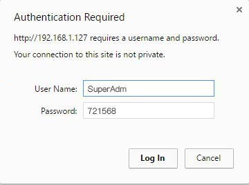
When you choose the “Networking Setting” or “User Password” at first. Log-in window will pop out and please input
At the Factory Default
User name: SuperAdm
Password: 721568 - Networking Setting
You will find initial IP Address 192.168.1.127 and check MAC Address is identical to the sticker on Ethernet Module device. Please alter the IP address as you want, and then click “Update” button. After updating the IP, please re-connect the Web Browser by the new IP address.

- User Password
Change the log-in password to lock the IP setting of Ethernet Module.
The password is composed of 10 characters at most which can be either A~Z or 0~9.
Documents / Resources
 |
SOYAL AR-837-E LCD Access Controller [pdf] Installation Guide AR-837-E, LCD Access Controller, AR-837-E LCD Access Controller |


