![]() 5-054-939-31 (1)
5-054-939-31 (1)
Virtual Production Tool Set
Color Calibrator
User Guide
Software Version 2.0
Introduction
Overview
About Color Calibrator
“Color Calibrator” is an application that measures and calibrates the color reproduction characteristics of displays and cameras used in a virtual production environment.
It accepts X-OCN files captured using the Sony MPC-36 10 (VENICE / CineAltaV), MPC -3626/ MPC-3628 (VENICE 2 / CineAltaV 2), and MPC-26 10 (BURANO / CineAltaB) Digital
Cinema Cameras or SDI output signals from a camera that supports S-Log3, and generates 3D LUT files used for calibration (correction of color characteristics).
The calibration operation is performed in conjunction with the “Camera and Display Plugin” Unreal Engine plugin.
Software Licenses
A software license (available separately) is required to generate calibration result 3D LUT files.
Install a software license by selecting [Help] menu > [Install License] in Color Calibrator. You can also install a license using the [Install License] button displayed in the [Color Manager] window.
For details about installing a software license, refer to the license installation guide.
The installation guide can be downloaded from the purchase site.
Accessing Software to which the LGPL Applies
This product uses Qt software to which the LGPL applies. This informs you that you have a right to have access to, modify, and redistribute source code for software programs under the conditions of the LGPL. For details about obtaining the source code, contact technical support at http://www.sonycreativesoftware.com/support/camerautilities.
We would prefer that you do not contact us about the contents of the source code.
Usage Precautions
Software Usage
This manual or the software described herein, in whole or in part, may not be reproduced, translated or reduced to any machine readable form without prior written approval from Sony Corporation.
© 2023, 2024 Sony Corporation
SONY CORPORATION PROVIDES NO WARRANTY WITH REGARD TO THIS MANUAL, THE SOFTWARE OR OTHER INFORMATION CONTAINED HEREIN AND HEREBY EXPRESSLY DISCLAIMS ANY IMPLIED WARRANTIES OF MERCHANTABILITY OR FITNESS FOR ANY PARTICULAR PURPOSE WITH REGARD TO THIS MANUAL, THE SOFTWARE OR SUCH OTHER INFORMATION. IN NO EVENT SHALL SONY CORPORATION BE LIABLE FOR ANY INCIDENTAL, CONSEQUENTIAL OR SPECIAL
DAMAGES, WHETHER BASED ON TORT, CONTRACT, OR OTHERWISE, ARISING OUT OF OR IN CONNECTION WITH THIS MANUAL, THE SOFTWARE OR OTHER INFORMATION CONTAINED HEREIN OR THE USE THEREOF.
This software may only be used with the specified device.
Sony Corporation reserves the right to make any modification to this manual or the information contained herein at any time without notice.
Security
SONY WILL NOT BE LIABLE FOR DAMAGES OF ANY KIND RESULTING FROM A FAILURE TO IMPLEMENT PROPER SECURITY MEASURES ON TRANSMISSION DEVICES, UNAVOIDABLE DATA LEAKS RESULTING FROM TRANSMISSION SPECIFICATIONS, OR SECURITY PROBLEMS OF ANY KIND.
About This Manual
Trademarks
- Windows is a trademark or registered trademark of Microsoft Corporation in the U.S. and/or other countries.
- Intel is a trademark or registered trademark of Intel Corporation or its subsidiaries.
- AMD and AMD Radeon are trademarks of Advanced Micro Devices, Inc.
- NVIDIA and GeForce GTX are trademarks and/or registered trademarks of NVIDIA Corporation in the U.S. and/or other countries.
- Unreal Engine is a trademark or registered trademark of Epic Games, Inc. in the United States of America and elsewhere.
- XAVC is a registered trademark of Sony Corporation.
All system names, product names, and company names appearing in this document are registered trademarks or trademarks of their respective owners.
Trademarked items are not indicated by ® or ™ symbols in this document.
About the Display Screen
The displayed screen may vary from that shown in this document, depending on the computer and operating environment.
Preparation
Setup
Operating Environment
Operating conditions
To use the application, an Internet connection is required when launched for the first time and every 28 days thereafter to access the license server.
The proxy server for Internet connection uses the Windows OS proxy settings.
[Note]
The application is enabled for 28 days after accessing the license server.
Note that when working offline, you will need to connect to the Internet and access the license server every 28 days.
Recommended operating environment
OS:
Windows 10 (64-bit)
CPU:
Quad core Intel (4th generation Core or later) or AMD (Zen series or later), 2.5 GHz or higher
Memory:
6 GB RAM or higher
HDD:
500 MB free space or higher
GPU:
AMD Radeon RX 400 series or later NVIDIA GeForce GTX 750 series or later
Monitor:
1920×1080 or higher
Supported devices
Camera:
MPC-3610 (VENICE / CineAltaV)
MPC-3626 and MPC-3628 (VENICE 2 / CineAltaV 2)
MPC-2610 (BURANO / CineAltaB)
ILME-FR7: Only SDI connection supported
HDC-5500 and HDC-5500V version 3.01 or
later: Only SDI connection supported
HDC-F5500 version 3.01 or later: Only SDI
connection supported
HDC-3500 and HDC-3500V version 3.01 or later: Only SDI connection supported
SDI capture card:
Decklink 8K Pro
Decklink 4K Extreme
manufactured by Blackmagic Design
[Note]
SDI capture cards are required only for input of the output signal from a camera using SDI connection.
Installing Color Calibrator
This section describes how to install Color Calibrator using the “ColorCalibrator_xxxxx. msi” installer.
The “xxxxx” part of the file name indicates the version of the application.
- Run “ColorCalibrator_xxxxx.msi.”
The setup wizard launches. - Click the [Next] button.

- When the software end user license agreement appears, check the contents.
- Place a check mark in [I accept the terms in the License Agreement] to proceed, and click the [Next] button.

- Specify the installation destination folder and click the [Next] button.

- To create a shortcut on the desktop, place a check mark in [Create a desktop shortcut] and click the [Next] button.
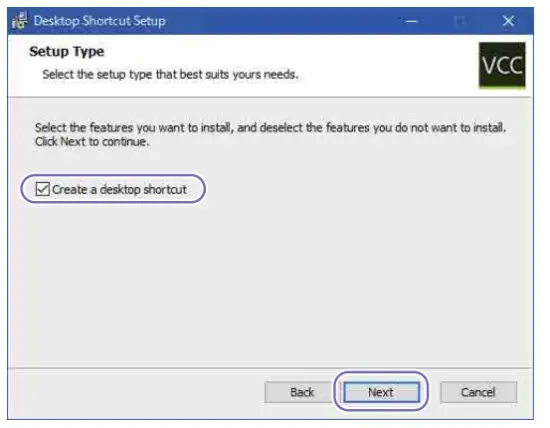 To continue without creating a shortcut, leave the checkbox empty and click the [Next] button.
 - When the ready to install screen appears, click the [Install] button.
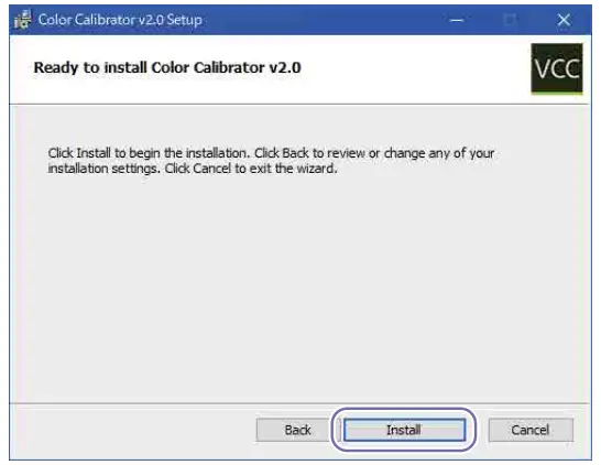 Installation of the application begins.
 - When the installation completed screen appears, click the [Finish] button.

SDI Connection with Camera
You can perform a calibration by inputting the SDI output signal from a camera directly into Color Calibrator.
To use SDI connection, attach a supported SDI capture card to the computer running Color Calibrator.
For details about SDI capture cards, see “Supported devices” (page 6).
Supported output signals
The SDI connection supports the following output signals.
Resolution: 1920×1080
Frame rate and signal format:
23.98/24/25/29.97 (PsF or Progressive,
YPbPr, 1.5G)
50/59.94 (Progressive, YPbPr, 3G)
Color space:
S-Gamut3/SLog3
S-Gamut3.Cine/SLog3
Calibration Operations
Overview of Calibration Operations
Color Calibrator performs calibration in conjunction with the “Camera and Display Plugin” Unreal Engine plugin.
For details about the plugin, refer to the Camera and Display Plugin manual.
Calibration operation workflow The basic operation workflow for calibration is shown below.

Calibration Types
Color Calibrator performs calibration to match the display mode (HDR or SDR) of the display and the luminance management operating mode (Mode A or Mode B).
It supports the following four types of calibration according to the combinations of the display mode of the display and the luminance management operating mode.
- HDR & Mode A
- HDR & Mode B
- SDR & Mode A
- SDR & Mode B
Display mode of the display
Select the type of calibration to match the display mode (HDR or SDR) of the display used when shooting.
HDR
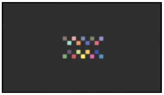
When the display mode of the display is HDR, display an HDR image (color chart) and measure the color characteristics of the display and camera.
This mode enables you to calibrate color reproduction characteristics that include HDR high luminance characteristics.
SDR
When the display mode of the display is SDR, display an SDR image (color chart) and measure the color characteristics of the display and camera.
This mode enables you to calibrate SDR color reproduction characteristics.
[Note]
With SDR, calibration performance may not be obtained, depending on the display characteristics of the display.
If calibration performance is not obtained, it is recommended to adjust the display settings of the display or switch to HDR operation.
Luminance management operating mode
Select the type of calibration to match the operating mode (Mode A or Mode B) set using [Sensitivity Simulation] of a Virtual Camera actor of the Camera and Display Plugin.
[Note]
In Mode B operating mode, a lens with T value indicator and RDD18 metadata are required. In Color Calibrator, Mode B can be selected only when importing an X-OCN file or when inputting an SDI output signal that has RDD18 metadata.
The Mode B functionality is in beta. This is an experimental feature, so conduct sufficient testing before operating in Mode B.
Mode A
This is an operating mode where the deviation in optical luminance between an actual display and camera is included in a Virtual Camera actor.
In Mode A, the brightness of the output video from a Virtual Camera actor changes in thesame way as the actual shooting environment, depending on the type of display used in the virtual space.
Mode A calibrates the luminance and color of the output video of a real camera so that it matches the output video of a Virtual Camera actor.
Mode B (Beta)
This is an operating mode where the deviation in optical luminance between an actual display and camera is not included in a Virtual Camera actor.
In Mode B, the brightness of the output video from a Virtual Camera actor does not change, depending on the type of display used in thevirtual space.
Mode B calibrates the luminance and color of the output video of a real camera so that it matches the output video of a Virtual Camera actor.
[Note]
In Mode A, the brightness of the display (inner frustum) does not change when the 3D LUT for calibration is applied.
Use Mode A when not using a Virtual Camera actor in the pre-vis process or when there is no need to calibrate the luminance of a Virtual Camera actor and a real camera.
In Mode B, the deviation in optical brightness between the actual display and the camera is included in the 3D LUT for calibration, so applying the 3D LUT changes the brightness of the actual display (inner frustum).
Basic Operation
Color Calibrator and the On-set Camera component of the Camera and Display Plugin are used for calibration operations.
The calibration procedure will vary depending on the calibration type. Perform the calibration to match the type.
For details about calibration types, see “Calibration Types” (page 9).
For details about calibration when using a system camera (HDC series), see “System Camera Calibration Operation” (page 15).
“HDR & Mode A” Type Calibration Operation
Use the following calibration procedure when the display mode of the display is HDR and the luminance management operating mode is Mode A.
- Set the calibration chart to “W100” in the On-set Camera component.
The W100 chart appears on the display.
For details, see “Displaying Color Charts on the Display” (page 21). - Check the display settings.
The display must be set to the appropriate settings for successful calibration.
Check that the display is configured as follows.
• Color space setting of the display controller matches the color chart.
• W100 chart is displayed at 100 nits emission (check by measuring the display using a spectral radiance meter or other device).
For details, see “Configuring a Display” (page 23). - Check the camera settings.
Check that the camera is configured as follows.
For details, refer to the manual for the camera.
• Input Color Space:
“S-Gamut3.Cine/SLog3” or “S-Gamut3
SLog3”
• Recording Format:
X-OCN video format
• ND Filter:
“Clear”
• White Balance:
“6500K” On cameras that cannot be set to “6500K,” set to the value closest to 6500K.
• Exposure Index:
VENICE 2 8K (CineAltaV 2 8K) / BURANO (CineAltaB): “800EI”
VENICE 2 6K (CineAltaV 2 6K) / VENICE (CineAltaV): “500EI”
For other cameras, set to match the “Base ISO” setting.
• Base ISO:
VENICE 2 8K (CineAltaV 2 8K) / BURANO (CineAltaB): “ISO 800”
VENICE 2 6K (CineAltaV 2 6K) / VENICE (CineAltaV): “ISO 500”
For other cameras, set the Low “Base ISO” setting.
[Notes]
• When an output signal from a BURANO (CineAltaB) is input via SDI connection, set the codec to XAVC.
• There are no restrictions on the “FPS” and “Shutter” settings, but at high shutter speeds, flicker may occur if the display and camera are not synchronized.
• When operating using a display with a color temperature other than 6500K, set “White Balance” to match the color temperature of the display. - Check the camera viewfinder settings.
The camera viewfinder must be set to the appropriate settings for successful calibration.
Check that the viewfinder is configured as follows.
• Zebra function of the viewfinder is enabled.
• Zebra display of the viewfinder is set to zebra 2 (display level of 61%).
• Output video of the viewfinder is set to Log.
For details, see “Configuring Camera Output” (page 25).
[Note]
If the zebra function cannot be used, use a waveform monitor or the [Waveform] window of Color Calibrator. Input the camera output video (Log) to the waveform monitor or Color Calibrator and check that the signal waveform is displayed. - Adjust the exposure by shooting a W100 chart using the camera.
Set the exposure (61%) appropriate for shooting a color chart in S-Log3. Adjust the shutter and iris to set the exposure so that the zebra appears on the W100 chart when viewed in the viewfinder.
The zebra is displayed when the exposure is 61% or higher. When the exposure is set such that the zebra starts to appear, the W100 chart will be captured at 61% exposure.
[Note]
If the zebra function cannot be used, check the camera output signal in a waveform monitor or the [Waveform] window of Color Calibrator, and adjust the shutter and aperture so that the W100 chart luminance level is 61% or 100 nits in nits display mode. - Set the calibration chart to “HDR1” in the On-set Camera component.
The HDR1 chart appears on the display.
For details, see “Displaying Color Charts on the Display” (page 21).
[Note]
Check that the color space setting of the display controller matches the color chart. - Shoot and record the HDR1 chart using the camera.
Shoot the HDR1 chart using the camera and record to a file in X-OCN format.
Observe the following when shooting the color chart.
• Turn off all lighting in the shooting location and do not use any lighting other than the display.
• Check that nothing is displayed in the outer frustum surrounding the chart display area. If anything other than the chart is displayed, it may be reflected onto the chart and affect the accuracy of calibration.
• Place the chart in the center of the display screen, leaving some space around the chart. When shooting, this helps suppress the effects of peripheral light reduction of the lens.
• Make sure that the chart is not in focus. If you are focused on the display surface, moiré may occur.
When an output signal from a camera is input to Color Calibrator via SDI connection
Calibration is performed by direct input of the video captured by the camera, so there is no need to record to a file.
When using SDI connection, set the SDI output video to Log.
For details, see “Configuring Camera Output” (page 25). - Shoot and record the “HDR2,” “HDR3,” and “HDR4” charts.
Repeat steps 6 to 7 to shoot and record the HDR2 chart, HDR3 chart, and HDR4 chart in the same way. - Access the X-OCN files recorded in step 7 from the computer running Color Calibrator.
If direct access is not possible, transfer the files to the computer.
When an output signal from a camera is input to Color Calibrator via SDI connection
Input the video captured by the camera directly. Access to files is not required. - Sample the HDR1 chart to HDR4 chart using Color Calibrator.
Sample the captured color charts.
When the calibration type is HDR & Mode A, set [Chart] to [HDR] and [Calibration Mode] to [ModeA] in the [Color Manager] window.
For details, see “Sampling a Color Chart” (page 17). - Perform calibration using Color Calibrator.
Click the [Calibrate] button in the [Color Manager] window to perform calibration.
Click the [Calibration] button in the [Monitor] window to check the calibration result. The [Calibration] button shows the calibration result based on simulation values.
For details, see “Performing Calibration” (page 19). - Generate a 3D LUT file (*.cube) using Color Calibrator.
Click the [Export] button in the [Color Manager] window to generate a 3D LUT file.
For details, see “Generating a 3D LUT File” (page 20). - Set the 3D LUT file for calibration in the On-set Camera component.
Set the 3D LUT file generated in step 12 and check that the calibration is applied to the display.
For details, see “Applying a 3D LUT to the Display” (page 21). - Set the calibration chart to “HDR-Verify” in the On-set Camera component. The Verify chart appears on the display. For details, see “Displaying Color Charts on the Display” (page 21).
- Shoot and record the Verify chart using the camera. Shoot and record the Verify chart the same way as in step 7.
- Sample the Verify chart using Color Calibrator.
Sample the captured Verify chart.
For details, see “Sampling a Color Chart” (page 17). - Check the calibration result using Color Calibrator.
Click the [Verify] button in the [Monitor] window to check the calibration result with 3D LUT applied. The [Verify] button shows the actual calibration result, not a result based on simulation values.
Managing calibration data
The measurement data for calibration and the calibration result data can be saved as a project in Color Calibrator.
For details, see “[Color Manager] Window” (page 29).
“HDR & Mode B” Type Calibration Operation
Use the following calibration procedure when the display mode of the display is HDR and the luminance management operating mode is Mode B.
- Set the calibration chart to “W100” in the On-set Camera component.
The W100 chart appears on the display.
For details, see “Displaying Color Charts on the Display” (page 21). - Check the display settings.
The display must be set to the appropriate settings for successful calibration. Check that the display is configured as follows.
• Color space setting of the display controller matches the color chart.
• W100 chart is displayed at 100 nits emission (check by measuring the display using a spectral radiance meter or other device).
For details, see “Configuring a Display” (page 23). - Check the camera settings.
Check that the camera is configured as follows.
For details, refer to the manual for the camera.
• Input Color Space:
“S-Gamut3.Cine/SLog3” or “S-Gamut3/ SLog3”
• Recording Format:
X-OCN video format
• ND Filter:
“Clear”
• White Balance:
“6500K”
On cameras that cannot be set to
“6500K,” set to the value closest to
6500K.
• Exposure Index:
VENICE 2 8K (CineAltaV 2 8K) / BURANO (CineAltaB): “800EI”
VENICE 2 6K (CineAltaV 2 6K) / VENICE
(CineAltaV): “500EI”
For other cameras, set to match the
“Base ISO” setting.
• Base ISO:
VENICE 2 8K (CineAltaV 2 8K) / BURANO
(CineAltaB): “ISO 800”
VENICE 2 6K (CineAltaV 2 6K) / VENICE
(CineAltaV): “ISO 500”
For other cameras, set the Low “Base
ISO” setting.
• FPS:
“23.98”
• Shutter (angle):
“180”
• Iris (T value):
“T4.0”
[Notes]
• When an output signal from a BURANO (CineAltaB) is input via SDI connection, set the codec to XAVC.
• When operating using a display with a color temperature other than 6500K, set “White Balance” to match the color temperature of the display. - Set the calibration chart to “HDR1” in the On-set Camera component.
The HDR1 chart appears on the display.
For details, see “Displaying Color Charts on the Display” (page 21).
[Note]
Check that the color space setting of the display controller matches the color chart. - Shoot and record the HDR1 chart using the camera.
Shoot the HDR1 chart using the camera and record to a file in X-OCN format. Observe the following when shooting the color chart.
• Turn off all lighting in the shooting location and do not use any lighting other than the display.
• Check that nothing is displayed in the outer frustum surrounding the chart display area. If anything other than the chart is displayed, it may be reflected onto the chart and affect the accuracy of calibration.
• Place the chart in the center of the display screen, leaving some space around the chart. When shooting, this helps suppress the effects of peripheral light reduction of the lens.
• Make sure that the chart is not in focus. If you are focused on the display surface, moiré may occur. When an output signal from a camera is input to Color Calibrator via SDI connection Calibration is performed by direct input of the video captured by the camera, so there is no need to record to a file. When using SDI connection, set the SDI output video to Log. For details, see “Configuring Camera Output” (page 25). - Shoot and record the “HDR2,” “HDR3,” and “HDR4” charts.
Repeat steps 4 to 5 to shoot and record the HDR2 chart, HDR3 chart, and HDR4 chart in the same way. - Access the X-OCN files recorded in step 5 from the computer running Color Calibrator.
If direct access is not possible, transfer the files to the computer.
When an output signal from a camera is input to Color Calibrator via SDI connection
Input the video captured by the camera directly. Access to files is not required. - Sample the HDR1 chart to HDR4 chart using Color Calibrator.
Sample the captured color charts.
When the calibration type is HDR & Mode B, set [Chart] to [HDR] and [Calibration Mode] to [ModeB] in the [Color Manager] window.
For details, see “Sampling a Color Chart” (page 17). - Perform calibration using Color Calibrator. Click the [Calibrate] button in the [Color Manager] window to perform calibration. Click the [Calibration] button in the [Monitor] window to check the calibration result. The [Calibration] button shows the calibration result based on simulation values. For details, see “Performing Calibration” (page 19).
- Generate a 3D LUT file (*.cube) using Color Calibrator.
Click the [Export] button in the [Color Manager] window to generate a 3D LUT file.
For details, see “Generating a 3D LUT File” (page 20). - Set the 3D LUT file for calibration in the On-set Camera component. Set the 3D LUT file generated in step 10 and check that the calibration is applied to the display.
For details, see “Applying a 3D LUT to the Display” (page 21). - Set the calibration chart to “HDR-Verify” in the On-set Camera component.
The Verify chart appears on the display.
For details, see “Displaying Color Charts on the Display” (page 21). - Shoot and record the Verify chart using the camera.
Shoot and record the Verify chart the same way as in step 5. - Sample the Verify chart using Color Calibrator.
Sample the captured Verify chart.
For details, see “Sampling a Color Chart” (page 17). - Check the calibration result using Color Calibrator.
Click the [Verify] button in the [Monitor] window to check the calibration resultwith 3D LUT applied. The [Verify] button shows the actual calibration result, not a result based on simulation values.
Managing calibration data
The measurement data for calibration and the calibration result data can be saved as a project in Color Calibrator.
For details, see “[Color Manager] Window” (page 29).
“SDR & Mode A” Type Calibration Operation
Use the following calibration procedure when the display mode of the display is SDR and the luminance management operating mode is Mode A.
- Set the calibration chart to “W100” in the On-set Camera component.
The W100 chart appears on the display.
For details, see “Displaying Color Charts on the Display” (page 21). - Check the display settings.
The display must be set to the appropriate settings for successful calibration. Check that the display is configured as follows.
• Color space setting of the display controller matches the color chart.
• W100 chart is displayed at appropriate luminance emission (check by measuring the display using a spectral radiance meter or other device).
For details, see “Configuring a Display” (page 23). - Check the camera settings.
Check that the camera is configured as follows.
For details, refer to the manual for the camera.
• Input Color Space: “S-Gamut3.Cine/SLog3” or “S-Gamut3/ SLog3”
• Recording Format:
X-OCN video format
• ND Filter: “Clear”
• White Balance: “6500K” On cameras that cannot be set to “6500K,” set to the value closest to 6500K.
• Exposure Index:
VENICE 2 8K (CineAltaV 2 8K) / BURANO (CineAltaB): “800EI” VENICE 2 6K (CineAltaV 2 6K) / VENICE (CineAltaV): “500EI”
For other cameras, set to match the “Base ISO” setting.
• Base ISO:
VENICE 2 8K (CineAltaV 2 8K) / BURANO (CineAltaB): “ISO 800”
VENICE 2 6K (CineAltaV 2 6K) / VENICE (CineAltaV): “ISO 500”
For other cameras, set the Low “Base ISO” setting.
[Notes]
• When an output signal from a BURANO (CineAltaB) is input via SDI connection, set the codec to XAVC.
• There are no restrictions on the “FPS” and “Shutter” settings, but at high shutter speeds, flicker may occur if the display and camera are not synchronized.
• When operating using a display with a color temperature other than 6500K, set “White Balance” to match the color temperature of the display. - Check the camera viewfinder settings.
The camera viewfinder must be set to the appropriate settings for successful calibration.
Check that the viewfinder is configured as follows.
• Zebra function of the viewfinder is enabled.
• Zebra display of the viewfinder is set to zebra 2 (display level of 61%).
• Output video of the viewfinder is set to Log.
For details, see “Configuring Camera Output” (page 25).
[Note]
If the zebra function cannot be used, use a waveform monitor or the [Waveform] window of Color Calibrator. Input the camera output video (Log) to the waveform monitor or Color Calibrator and check that the signal waveform is displayed. - Adjust the exposure by shooting a W100 chart using the camera. Set the exposure (61%) appropriate for shooting a color chart in S-Log3. Adjust the shutter and iris to set the exposure so that the zebra appears on the W100 chart when viewed in the viewfinder.
The zebra is displayed when the exposure is 61% or higher. When the exposure is set such that the zebra starts to appear, the W100 chart will be captured at 61% exposure.
[Note]
If the zebra function cannot be used, check the camera output signal in a waveform monitor or the [Waveform] window of Color Calibrator, and adjust the shutter and aperture so that the W100 chart luminance level is 61% or 100 nits in nits display mode. - Set the calibration chart to “SDR1” in the On-set Camera component.
The SDR1 chart appears on the display.
For details, see “Displaying Color Charts on the Display” (page 21).
[Note]
Check that the color space setting of the display controller matches the color chart. - Shoot and record the SDR1 chart using the camera. Shoot the SDR1 chart using the camera and record to a file in X-OCN format. Observe the following when shooting the color chart.
• Turn off all lighting in the shooting location and do not use any lighting other than the display.
• Check that nothing is displayed in the outer frustum surrounding the chart display area. If anything other than the chart is displayed, it may be reflected onto the chart and affect the accuracy of calibration.
• Place the chart in the center of the display screen, leaving some space around the chart. When shooting, this helps suppress the effects of peripheral light reduction of the lens.
• Make sure that the chart is not in focus. If you are focused on the display surface, moiré may occur.
When an output signal from a camera is input to Color Calibrator via SDI connection Calibration is performed by direct input of the video captured by the camera, so there is no need to record to a file. When using SDI connection, set the SDI output video to Log. For details, see “Configuring Camera Output” (page 25). - Shoot and record the “SDR2” and “SDR3” charts.
Repeat steps 6 to 7 to shoot and record the SDR2 chart and SDR3 chart in the same way. - Access the X-OCN files recorded in step 7 from the computer running Color Calibrator.
If direct access is not possible, transfer the files to the computer.
When an output signal from a camera is input to Color Calibrator via SDI connection
Input the video captured by the camera directly. Access to files is not required. - Sample the SDR1 chart to SDR3 chart using Color Calibrator.
Sample the captured color charts.
When the calibration type is SDR & Mode A, set [Chart] to [SDR] and [Calibration Mode] to [ModeA] in the [Color Manager] window.
For details, see “Sampling a Color Chart” (page 17). - Perform calibration using Color Calibrator. Click the [Calibrate] button in the [Color Manager] window to perform calibration. Click the [Calibration] button in the [Monitor] window to check the calibration result. The [Calibration] button shows the calibration result based on simulation values. For details, see “Performing Calibration” (page 19).
- Generate a 3D LUT file (*.cube) using Color Calibrator.
Click the [Export] button in the [Color Manager] window to generate a 3D LUT file.
For details, see “Generating a 3D LUT File” (page 20). - Set the 3D LUT file for calibration in the On-set Camera component.
Set the 3D LUT file generated in step 12 and check that the calibration is applied to the display.
For details, see “Applying a 3D LUT to the Display” (page 21). - Set the calibration chart to “SDR-Verify” in the On-set Camera component.
The Verify chart appears on the display.
For details, see “Displaying Color Charts on the Display” (page 21). - Shoot and record the Verify chart using the camera.
Shoot and record the Verify chart the same way as in step 7. - Sample the Verify chart using Color Calibrator.
Sample the captured Verify chart.
For details, see “Sampling a Color Chart” (page 17). - Check the calibration result using Color Calibrator.
Click the [Verify] button in the [Monitor] window to check the calibration result with 3D LUT applied. The [Verify] button shows the actual calibration result, not a result based on simulation values.
Managing calibration data
The measurement data for calibration and the calibration result data can be saved as a project in Color Calibrator.
For details, see “[Color Manager] Window” (page 29).
“SDR & Mode B” Type Calibration Operation
Use the following calibration procedure when the display mode of the display is SDR and the luminance management operating mode is Mode B.
- Set the calibration chart to “W100” in the On-set Camera component.
The W100 chart appears on the display.
For details, see “Displaying Color Charts on the Display” (page 21). - Check the display settings.
The display must be set to the appropriate settings for successful calibration. Check that the display is configured as follows.
• Color space setting of the display controller matches the color chart.
• W100 chart is displayed at appropriate luminance emission (check by measuring the display using a spectral radiance meter or other device).
For details, see “Configuring a Display” (page 23). - Check the camera settings.
Check that the camera is configured as follows.
For details, refer to the manual for the camera.
• Input Color Space:
“S-Gamut3.Cine/SLog3” or “S-Gamut3/ SLog3”
• Recording Format:
X-OCN video format
• ND Filter: “Clear”
• White Balance: “6500K”
On cameras that cannot be set to “6500K,” set to the value closest to 6500K.
• Exposure Index:
VENICE 2 8K (CineAltaV 2 8K) / BURANO (CineAltaB): “800EI”
VENICE 2 6K (CineAltaV 2 6K) / VENICE (CineAltaV): “500EI”
For other cameras, set to match the “Base ISO” setting.
• Base ISO: VENICE 2 8K (CineAltaV 2 8K) / BURANO (CineAltaB): “ISO 800” VENICE 2 6K (CineAltaV 2 6K) / VENICE (CineAltaV): “ISO 500”
For other cameras, set the Low “Base ISO” setting.
• FPS: “23.98”
• Shutter (angle): “180”
• Iris (T value): “T4.0”
[Notes]
• When an output signal from a BURANO (CineAltaB) is input via SDI connection, set the codec to XAVC.
• When operating using a display with a color temperature other than 6500K, set “White Balance” to match the color temperature of the display. - Set the calibration chart to “SDR1” in the On-set Camera component.
The SDR1 chart appears on the display.
For details, see “Displaying Color Charts on the Display” (page 21).
[Note]
Check that the color space setting of the display controller matches the color chart. - Shoot and record the SDR1 chart using the camera.
Shoot the SDR1 chart using the camera and record to a file in X-OCN format. Observe the following when shooting the color chart.
• Turn off all lighting in the shooting location and do not use any lighting other than the display.
• Check that nothing is displayed in the outer frustum surrounding the chart display area. If anything other than the chart is displayed, it may be reflected onto the chart and affect the accuracy of calibration.
• Place the chart in the center of the display screen, leaving some space around the chart. When shooting, this helps suppress the effects of peripheral light reduction of the lens.
• Make sure that the chart is not in focus. If you are focused on the display surface, moiré may occur. When an output signal from a camera is input to Color Calibrator via SDI connection Calibration is performed by direct input of the video captured by the camera, so there is no need to record to a file. When using SDI connection, set the SDI output video to Log. For details, see “Configuring Camera Output” (page 25). - Shoot and record the “SDR2” and “SDR3” charts.
Repeat steps 4 to 5 to shoot and record the SDR2 chart and SDR3 chart in the same way. - Access the X-OCN files recorded in step 5 from the computer running Color Calibrator.
If direct access is not possible, transfer the files to the computer.
When an output signal from a camera is input to Color Calibrator via SDI connection Input the video captured by the camera directly. Access to files is not required. - Sample the SDR1 chart to SDR3 chart using Color Calibrator.
Sample the captured color charts.
When the calibration type is SDR & Mode B, set [Chart] to [SDR] and [Calibration Mode] to [ModeB] in the [Color Manager] window. Also, set [Display Controller], [Light Output], [Contrast], and [Peak Luminance] to match your display/display controller.
For details, see “Sampling a Color Chart” (page 17). - Perform calibration using Color Calibrator.
Click the [Calibrate] button in the [Color Manager] window to perform calibration.
Click the [Calibration] button in the [Monitor] window to check the calibration result. The [Calibration] button shows the calibration result based on simulation values. For details, see “Performing Calibration” (page 19). - Generate a 3D LUT file (*.cube) using Color Calibrator.
Click the [Export] button in the [Color Manager] window to generate a 3D LUT file.
For details, see “Generating a 3D LUT File” (page 20). - Set the 3D LUT file for calibration in the On-set Camera component.
Set the 3D LUT file generated in step 10 and check that the calibration is applied to the display.
For details, see “Applying a 3D LUT to the Display” (page 21). - Set the calibration chart to “SDR-Verify” in the On-set Camera component.
The Verify chart appears on the display.
For details, see “Displaying Color Charts on the Display” (page 21). - Shoot and record the Verify chart using the camera.
Shoot and record the Verify chart the same way as in step 5. - Sample the Verify chart using Color Calibrator.
Sample the captured Verify chart.
For details, see “Sampling a Color Chart” (page 17). - Check the calibration result using Color Calibrator.
Click the [Verify] button in the [Monitor] window to check the calibration result with 3D LUT applied. The [Verify] button shows the actual calibration result, not a result based on simulation values.
Managing calibration data
The measurement data for calibration and the calibration result data can be saved as a project in Color Calibrator.
For details, see “[Color Manager] Window” (page 29).
System Camera Calibration Operation
System cameras support shooting of HDR displays in SDR (with HDR mode set to “Off”) only.
However, calibration uses the “HDR & Mode Atype procedure using “Cinema” in HDR mode
[Note]
System cameras do not support calibration operations using an X-OCN file. Input an output signal from a camera via SDI connection to Color Calibrator.
“HDR & Mode A” type
Perform an “HDR & Mode A” type calibration using the following procedure and set the display mode of the display to SDR.
- Set the calibration chart to “W100” in the On-set Camera component.
The W100 chart appears on the display.
For details, see “Displaying Color Charts on the Display” (page 21). - Check the display settings.
The display must be set to the appropriate settings for successful calibration.
Check that the display is configured as follows.
• Color space setting of the display controller matches the color chart.
• W100 chart is displayed at 100 nits emission (check by measuring the display using a spectral radiance meter or other device).
For details, see “Configuring a Display” (page 23). - Check the camera settings.
Check that the camera is configured as follows.
For details, refer to the manual for the camera and MSU (master setup unit).
• OETF: “S-Log3(Cinema)”
• Color Space: “SG3” or “SG3C”
• Flare: “OFF”
• Gain: Total Gain “0 dB”
• White: When 5600K is off: R “64” / G “0” / B “–79”
• ND filter: “CLEAR”
• CC filter: “3200K”
[Notes]
• The camera configuration items are described using the settings on an MSU as an example.
• There are no restrictions on the “FPS” and “Shutter” settings, but at high shutter speeds, flicker may occur if the display and camera are not synchronized.
• When operating at a display color temperature other than 6500K, select the appropriate CC filter, then set the G value of “White” to 0 and adjust the R and B values so that the W100 chart is displayed white. - Connect the camera and a waveform monitor.
The camera and waveform monitor must be set to the appropriate connection for successful calibration.
You can also use the [Waveform] window of Color Calibrator as a waveform monitor.
Input the camera output video (Log) to the waveform monitor or Color Calibrator and check that the signal waveform is displayed. - Adjust the exposure by shooting a W100 chart using the camera.
Set the exposure (61%) appropriate for shooting a color chart in S-Log3.
Check the camera output signal in a waveform monitor or the [Waveform] window of Color Calibrator, and adjust the shutter and aperture so that the W100 chart luminance level is 61% or 100 nits in nits display mode. - Set the calibration chart to “HDR1” in the On-set Camera component.
The HDR1 chart appears on the display.
For details, see “Displaying Color Charts on the Display” (page 21).
[Note]
Check that the color space setting of the display controller matches the color chart. - Shoot the HDR1 chart using the camera and input the output signal to Color Calibrator.
Shoot the HDR1 chart using the camera and directly input the output signal from the camera via SDI connection to Color Calibrator.
Observe the following when shooting the color chart.
• Turn off all lighting in the shooting location and do not use any lighting other than the display.
• Check that nothing is displayed in the outer frustum surrounding the chart display area. If anything other than the chart is displayed, it may be reflected onto the chart and affect the accuracy of calibration.
• Place the chart in the center of the display screen, leaving some space around the chart. When shooting, this helps suppress the effects of peripheral light reduction of the lens.
• Make sure that the chart is not in focus. If you are focused on the display surface, moiré may occur. - Shoot and input the “HDR2,” “HDR3,” and “HDR4” charts to Color Calibrator.
Repeat steps 6 to 7 to shoot and input the HDR2 chart, HDR3 chart, and HDR4 chart in the same way. - Sample the HDR1 chart to HDR4 chart using Color Calibrator.
Sample the captured color charts.
When the calibration type is HDR & Mode A, set [Chart] to [HDR] and [Calibration Mode] to [ModeA] in the [Color Manager] window.
For details, see “Sampling a Color Chart” (page 17). - Perform calibration using Color Calibrator.
Click the [Calibrate] button in the [Color Manager] window to perform calibration.
Click the [Calibration] button in the [Monitor] window to check the calibration result. The [Calibration] button shows the calibration result based on simulation values.
For details, see “Performing Calibration” (page 19). - Generate a 3D LUT file (*.cube) using Color Calibrator.
Click the [Export] button in the [Color Manager] window to generate a 3D LUT file.
For details, see “Generating a 3D LUT File” (page 20). - Set the 3D LUT file for calibration in the On-set Camera component.
Set the 3D LUT file generated in step 11 and check that the calibration is applied to the display.
For details, see “Applying a 3D LUT to the Display” (page 21). - Set the calibration chart to “HDR-Verify” in the On-set Camera component.
The Verify chart appears on the display.
For details, see “Displaying Color Charts on the Display” (page 21). - Capture the Verify chart using the camera and input to Color Calibrator.
Capture and input the Verify chart the same way as in step 7. - Sample the Verify chart using Color Calibrator.
Sample the captured Verify chart.
For details, see “Sampling a Color Chart” (page 17). - Check the calibration result using Color Calibrator.
Click the [Verify] button in the [Monitor] window to check the calibration result with 3D LUT applied. The [Verify] button shows the actual calibration result, not a result based on simulation values.
Managing calibration data
The measurement data for calibration and the calibration result data can be saved as a project in Color Calibrator.
For details, see “[Color Manager] Window” (page 29).
The following operations are performed using Color Calibrator.
- Sample measurement image (color chart) from video captured by a camera.
- Perform calibration.
- Generate 3D LUT files for calibration.
- Compare and check calibration results.
- Manage calibration data as a project.
For details about screen operation, see “4. Color Calibrator Screen” (page 28).
Sampling a Color Chart
You can sample color charts used for calibration using Color Calibrator.
Capture an image (color chart) from video captured by a camera and record it as a measurement image.

- Create a project in the [Color Manager] window.
Create a project for saving calibration data in the project manager section.
Select a save destination folder, click the [New] button, and enter a project name.
A new project is created and is displayed in the calibration section in the [Color Manager] window.
To use an existing project Select a project and click the [Load] button.
The calibration data for the selected project is displayed in the calibration section.
To create a new folder Click the [New Folder] button and enter a folder name.
A folder is created in the selected folder. - Select the set of color chart images in [Chart].
HDR:
Set of images when the calibration type is HDR (display mode of the display is HDR).
SDR:
Set of images when the calibration type is SDR (display mode of the display is SDR). - Select the luminance management operating mode in [Calibration Mode].
ModeA:
Mode that reproduces the luminance captured by a camera on a Virtual Camera actor of the Camera and Display Plugin.
ModeB:
Mode that reproduces the luminance displayed by a Virtual Camera actor of the Camera and Display Plugin when shooting with a camera.
[Note]
Set to the same operating mode as [LED Settings] > [Sensitivity Simulation] of the Virtual Camera actor.
Set to [ModeA] when not using a Virtual Camera actor or when there is no need to calibrate the luminance of a Virtual Camera actor and a real camera. - Select the calibration configuration mode in [Calibration Setting]. Color&Linearity:
This mode is used to correct both luminance characteristics and color reproduction characteristics from measured values.
[Color&Linearity] is appropriate when the display mode of the display is HDR.
Color Only:
This mode is used to correct color reproduction characteristics only from measured values.
Only [Color Only] is configurable when the display mode of the display is SDR where there is often a difference in the luminance of the display between when calibrating and when shooting. Luminance characteristics are not calibrated. - If the calibration type is SDR & Mode B, set the display/display controller.
When [Chart] is set to [SDR] and [Calibration Mode] is set to [ModeB], configure the following settings to match your display/display controller.
Crystal LED and ZRCT-300 Set [Display Controller] to [ZRCT-300], then set the display optical output in [Light Output] and the contrast of the display in [Contrast].
[Note]
Set the same values for [Light Output] and [Contrast] as the display controller settings.
Other display/display controller
Set [Display Controller] to [Other], then set the peak luminance of the display in [Peak Luminance].
[Note]
Set the same value for [Peak Luminance] as the display controller setting. - Select a capture image area.
A blue frame is added to the selected capture image area.
Each capture image area (numbered 1 to 4 from the top) corresponds to the following color charts, depending on the [Chart] setting (HDR or SDR).Position HDR SDR 1 HDR1 chart SDR1 chart 2 HDR2 chart SDR2 chart 3 HDR3 chart SDR3 chart 4 HDR4 chart – - Display the video for calibration in the [Image Viewer] window.
When using SDI connection
Input the video captured by the camera.
When the [SDI Input] button is clicked, SDI connection becomes enabled. When the output signal from a camera is input to Color Calibrator correctly, the video being captured is displayed in the input image area.
The color space acquired from the RDD18 metadata embedded in the SDI input is displayed on the right of the [SDI Input] button.
If it cannot be acquired, the color space can be selected. Select the correct color space of the input signal.
[Note]
An error message is displayed if a signal format or color space not supported by SDI connection is detected.
When an error message is displayed, calibration cannot be performed, even when a video is being displayed in the input image area. Check the SDI connection to the camera and the output signal settings.
When using an X-OCN file Load an X-OCN video file captured by a camera.
When the [Read X-OCN] button is clicked, select a file to display the video in the input image area.
The file name and playback position (hour:minute:second:frame) are displayed at the top of the input image area. - Display the captured image of the target color chart.
Display the image of the color chart corresponding to the capture image area selected in step 6 in the input image area.
When using SDI connection Shoot the target color chart.
The following control buttons are available.
 button: Pauses/resumes video input.
 button: Loads 1 frame of the video currently being captured.
When using an X-OCN file
Move to the captured frame of the target color chart using the seek bar or control buttons.
The following control buttons are available.
 button: Moves to the previous frame.
button: Starts/stops playback.
button: Moves to the next frame. - Set the positions of the color measurement guides.
You can drag the marks at the four corners of the image and adjust them so that the color patches and marks (color measurement guides) overlap.
To change the size of the marks (color measurement guides)
You can adjust the size of the marks (color measurement guides) in [Average].
Set the marks (color measurement guides) so that they are about 70% to 80% the size of the image color patch.
 To zoom in/zoom out
You can zoom in/out in the input image area by moving the mouse wheel up/ down.
When zoomed in, a zoom indicator is displayed in the input image area. In the zoom indicator, the range displayed in the input image area is enclosed by a blue frame. You can change the display range by moving the blue frame.
 To adjust the marks (color measurement guides) automatically Click the
  (Auto adjustment) button. The position and size of the marks (color measurement guides) are adjusted automatically to match the color chart image.
 - Click the
 (Capture) button to register the image.
The image is registered in the capture image area selected in step 6.
[Note]
The color of the image in the capture image area is the average value of the color within the marks (color measurement guides). - Sample all the color charts.
Repeat steps 6 to 10 to sample the other charts in the same way.
To save the project
Click the [Save] button in the [Color Manager] window.
Sampling the Verify chart
Click the [+] button in the bottom left in the [Color Manager] window to display the Verify chart.
[Note]
The [+] button becomes enabled after calibration ends.

Sample the chart in the same way as the other charts. Register the captured image of the Verify chart in a capture image area.
When sampling is finished, check the calibration result in the [Monitor] window.
Click the [Verify] button in the [Monitor] window to compare the color chart (theoretical values) and calibration results as color patches or graphs.
For details, see “[Monitor] Window” (page 36).
Performing Calibration
You can perform calibration using Color Calibrator after sampling the color charts.

- Sample the color charts captured by the camera.
For details, see “Sampling a Color Chart” (page 17). - Click the [Calibrate] button in the [Color Manager] window.
The calibration is executed.
[Note]
Check that the correct luminance management operating mode is selected in [Calibration Mode] to match the calibration type. - Click the [Calibration] button in the [Monitor] window to check the calibration result.
A comparison of the color charts (theoretical values) and calibration result based on simulation is displayed as color patches or graphs.
For details, see “[Monitor] Window” (page 36).
Generating a 3D LUT File
You can generate a 3D LUT file (*.cube) using Color Calibrator after performing a calibration.

- Click the [Export] button in the [Color Manager] window.
The [Save as] dialog appears. - Specify the save destination folder and file name for the 3D LUT file.
- Select the color space of the input signal in [Input Color Space].
Set to [Rec2100(PQ)] to use the On-set Camera component. - Select the color space of the output signal in [Output Color Space].
Set to [Rec2100(PQ)] to use the On-set Camera component. - Click the [Save] button.
A 3D LUT file is generated.
On-set Camera Component Operation
The following operations are performed by the On-set Camera component of the Camera andDisplay Plugin.
- Display color charts on the display.
- Apply 3D LUT files for calibration to the display.
For details about On-set Camera component operations, refer to the Camera and Display Plugin manual.
Displaying Color Charts on the Display
You can display color charts for calibration on the display using the On-set Camera component of the Camera and Display Plugin.
Select the On-set Camera component in the [Details] panel of the camera actor, and configure the color space of the display in [LED Settings] and the color charts in [Calibration]in the [Sony On Set Camera] section.
For details, refer to the Camera and Display Plugin manual.

- Set the color space of the display in [LED Settings] > [Input Color Space]. Check that [Input Color Space] is configured to match the color space setting of the display.
Depending on the display controller, “PQ/ Native” color space may be configurable. If used, set [Input Color Space] to [HDR (Rec.2020/PQ)]. - Configure the OCIO settings using the [nDisplay OCIO Setting] button in [Input Color Space].
The OCIO settings of the nDisplay are set to match the color space of the display. - Place a check mark in [Display Chart] in [Calibration] > [Calibration Chart].
- Select the color chart to display in [Chart Type] in [Calibration Chart].
The selected color chart appears on the display. - Set the size (0.1 to 1.0) of the color chart to display in [Chart Scale] in [Calibration Chart].
Selecting a color chart
Select a chart to match the color charts for calibration specified in [Chart Type] of the Onset Camera component.
• When the calibration type is HDR
| Color chart | [Chart Type] |
| W100 chart | W100 |
| HDR1 chart | HDR1 |
| HDR2 chart | HDR2 |
| HDR3 chart | HDR3 |
| HDR4 chart | HDR4 |
| Verify chart | HDR-Verify |
• When the calibration type is SDR
| Color chart | [Chart Type] |
| W100 chart | W100 |
| SDR1 chart | SDR1 |
| SDR2 chart | SDR2 |
| SDR3 chart | SDR3 |
| Verify chart | SDR-Verify |
Checking the color chart display
Check that the color chart configured in the On-set Camera component is displayed correctly on the real display.
- Color chart display in On-set Camera component
 Color chart display on the display
[Notes]
- Check that nothing is displayed in the outer frustum surrounding the chart display area. If anything other than the chart is displayed, it may be reflected onto the chart and affect the accuracy of calibration.
- Place the chart in the center of the display screen, leaving some space around the chart. When shooting, this helps suppress the effects of peripheral light reduction of the lens.
Applying a 3D LUT to the Display
You can apply a 3D LUT for calibration, generated using Color Calibrator, to the display using the On-set Camera component of the Camera and Display Plugin.
Select the On-set Camera component in the [Details] panel of the camera actor, and configure the 3D LUT settings in [Calibration] in the [Sony On Set Camera] section.
For details, refer to the Camera and Display Plugin manual.

- Set the 3D LUT file (*.cube) generated using Color Calibrator in [LUT Filename] in [Calibration LUT].
When you click the [Add] button and select a 3D LUT file, the file is added to the [LUT Filename] drop-down list and becomes available for selection.
[Note]
The color space that is set when generating a 3D LUT file must match the OCIO settings of the nDisplay. - Place a check mark in [Enable] in [Calibration LUT].
[Calibration LUT] is enabled and the settings for the selected 3D LUT file are applied.
[Note]
When calibrating by displaying a color chart, first disable [Calibration LUT].
When using the Crystal LED B-series
When calibrating using Color Calibrator with [Chart] set to [HDR] and [Calibration Setting] set to [Color&Linearity], set [Calibration LUT] > [Crystal LED B-series Settings] of the On-set Camera component to correctly match the display controller. When set correctly, linearity correction is applied properly.
If the display controller settings are changed, you can still apply the calibration without regenerating a 3D LUT file by setting [Crystal LED B-series Settings] to the same settings.
Configuring a Display
The display must be set to the appropriate settings for successful calibration.
Observe the following when performing a calibration.
When the display mode of the display is HDR
- Check that the color space of the display is set to the same color space as [Input Color Space] in [LED Settings] of the On-set Camera component.
- Measure the display using a spectral radiance meter or other device and check that 100 nits is being emitted from the W100 chart.
- As a general rule, it is recommended that you set the color temperature of the display to 6500K. Operation is supported using a different setting, depending on the environment. In this case, set “White Balance” on the camera to match the color temperature of the display.
When the display mode of the display is SDR
- Check that the color space of the display is set to the same color space as [Input Color Space] in [LED Settings] of the On-set Camera component.
- Set the display controller so that an appropriate luminance is emitted from a W100 chart and check by measuring the display using a spectral radiance meter or other device.
- As a general rule, it is recommended that you set the color temperature of the display to 6500K. Operation is supported using a different setting, depending on the environment. In this case, set “White Balance” on the camera to match the color temperature of the display.
Display Configuration Method
This section describes how to configure the display using Display Control Software (version 1.05) with the following devices.
- Sony Crystal LED B-series
- ZRCT-300 Display Controller
For details, refer to the Display Control Software manual.

When the display mode of the display is HDR
Configure each item as follows using Display
Control Software.
Contrast:
“600”
Brightness:
“500”
Gamma:
Set to arbitrary value.
HDR:
Set to a curve matching the shooting environment.
Must match the color chart configured in the On-set Camera component. When the color chart setting is “HDR (Rec.2020/PQ),” select “SMPTE ST 2084.”
Color Space:
Set to the color space matching the shooting environment.
Must match the color chart configured in the On-set Camera component.
Transfer Matrix:
Set to match the transfer matrix of the device that is input to the display controller.
Light Output: “Step6”
When the display mode of the display is SDR
Configure each item as follows using Display Control Software.
Contrast: Set to arbitrary value.
Brightness: “500”
Gamma: Set to a curve matching the shooting environment.
Must match the color chart configured in the On-set Camera component.
HDR: “Off”
Color Space: Set to the color space matching the shooting environment.
Must match the color chart configured in the On-set Camera component.
Transfer Matrix: Set to match the transfer matrix of the device that is input to the display controller.
Light Output: Set to arbitrary value.
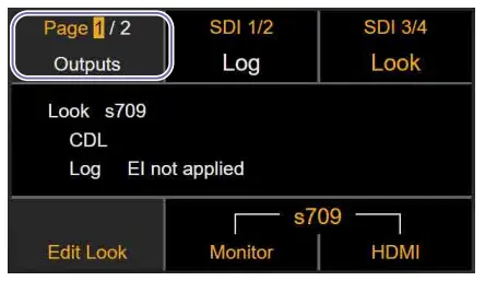
Configuring Camera Output
When the calibration type is Mode A, set the zebra function and output video of the viewfinder appropriately. In Mode A, standard white in S-Log3 must be set to 61 IRE when shooting a color chart. Use the zebra function of the viewfinder to adjust the rightness. Also, when an output signal from a camera is input to Color Calibrator via SDI connection, set the SDI output video to Log. The SDI connection supports output signals with “S-Gamut3/SLog3” or “S-Gamut3.Cine/SLog3” color space.
Configuring VENICE 2 (CineAltaV 2)
Configuring the zebra function of the viewfinder
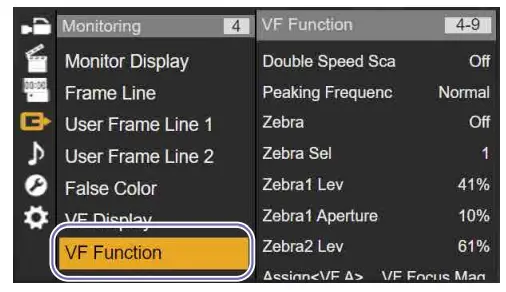
- Press and hold the MENU button to display the full menu on the sub display.
- Select Monitoring > VF Function in the menu and configure the zebra function.
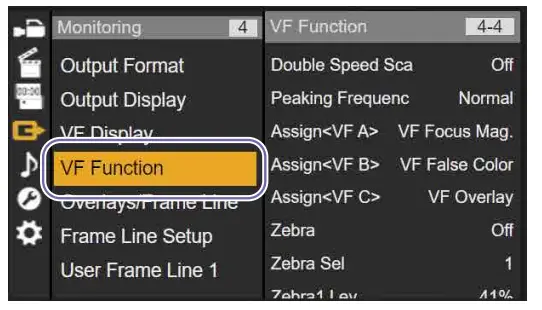
Configure the following settings.
- Zebra:
“On” - Zebra Select:
“2” - Zebra2 Level:
Check that the value is set to “61%.”
Configuring the viewfinder output video
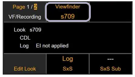
- Press the HOME button to display the Home screen.
- Press ITEM key 5 to select the item in the bottom center.

- Press ITEM key 3 to select the item in the top right (Viewfinder).

- Select [Log].
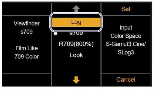 The output video of the viewfinder is set to Log.
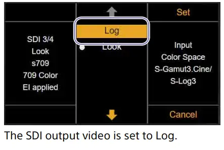
Configuring the SDI output video
Configure the following when using SDI connection.
- Press the HOME button to display the Home screen.
- Press ITEM key 5 to select the item in the bottom center.

- Press ITEM key 1 to select the item in the top left (SDI 1/2), or press ITEM key 2 to select the item in the top center (SDI 3/4).

- Select [Log].
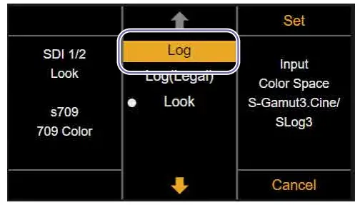 The SDI output video is set to Log.
Configuring VENICE (CineAltaV)
Configuring the zebra function of the viewfinder
- Press and hold the MENU button to display the full menu on the sub display.
- Select Monitoring > VF Function in the menu and configure the zebra function.
 Configure the following settings.
• Zebra: “On”
• Zebra Select: “2”
• Zebra2 Level: Check that the value is set to “61%.”
Configuring the viewfinder output video
- Press the HOME button to display the Home screen.
- Press ITEM key 5 to select the item in the bottom center.

- Press ITEM key 1 to switch to page 2.
- Press ITEM key 2 to select the item in the top center (Viewfinder).
- Select [Log].

The output video of the viewfinder is set to Log.
Configuring the SDI output video Configure the following when using SDI output 3/4 via SDI connection.
[Note]
When “RM/RCP Paint Control” is set to “Off” on VENICE (CineAltaV), the SDI 1/2 output video is set to Log (fixed).
When using SDI 1/2, configuring the SDI output video is not required.
- Press the HOME button to display the Home screen.
- Press ITEM key 5 to select the item in the bottom center.

- Press ITEM key 3 to select the item in the top right (SDI 3/4).

- Select [Log].
Configuring BURANO (CineAltaB)
Configuring the zebra function of the viewfinder
- Press and hold the MENU button to display the full menu on the sub display.
- Select Monitoring > Zebra in the menu and configure the zebra function.

Configure the following settings.
• Setting:
“Zebra2”
• Zebra2 Level:
Set to “61%.”
Configuring the viewfinder output video
- Press and hold the MENU button to display the full menu on the sub display.
- Select Shooting > LUT On/Off in the menu and set [LCD/Proxy/Stream] to [LUT Off].

Configuring the SDI output video
Configure the following when using SDI connection.
- Press the HOME button to display the Home screen.
- Press ITEM key 5 to select the item in the bottom center.

- Press ITEM key 1 to select the item in the top left (SDI).

- Select [Log].

The SDI output video is set to Log.
Screen Structure
Color Calibrator is comprised by a menu bar and five operation windows.
Each operation window can be displayed as a floating window or as a docked window using the following methods.
- Double-clicking the window title.
- Moving a window by clicking the center or edge of the screen and using drag & drop.

- Menu bar
- [Image Viewer] window (page 33)
- [Color Manager] window (page 29)
- [Waveform] window (page 35)
- [Monitor] window (page 36) /
[Metadata] window (page 38)
Switches between the display of the [Monitor] window and [Metadata] window using the window selection tabs.
Menu bar
Displays the following menus.
[File] menu:
Select [Exit] to exit Color Calibrator.
[Project] menu:
The following project operations in the
[Color Manager] window can be executed
from the menu.
[New], [New Folder], [Load], [Save], [Save
As], [Rename], [Delete]
[Window] menu:
Use to show/hide the following Color Calibrator windows.
[Color Manager], [Image Viewer],
[Waveform], [Monitor], [Metadata]
[Help] menu:
Select [Privacy Policy] to display the privacy policy. You can also change the terms of the agreement.
Select [Install License] to create a device information file (DEVICE.DAT) required for purchasing a software license and install the license file.
Select [About Color Calibrator] to display the Color Calibrator version information.
[Color Manager] Window
The [Color Manager] window is used to manage projects, register images for measurement (sampling), perform calibration, and generate 3D LUT files (*.cube).

| No. | Item | Description |
| 1 | Project manager section | Use to perform project tasks.
The project manager saves and manages calibration measurement data and calibration result data as a “project.” |
| 2 | Calibration section | Use to perform calibration tasks. Register images for measurement, perform calibration, and generate 3D LUT files. For details, see “Calibration section” (page 30). You can check the calibration result via simulation in the [Monitor] window after performing calibration. |
| 3 | Verify chart section | Use to perform tasks to verify the calibration result. Register measurement images to which the 3D LUT is applied. For details, see “Verify chart section” (page 32). You can check the actual calibration result in the [Monitor] window by registering an image in the capture image area. |
Project manager section

| No. | Item | Description |
| 1 | Project list | Displays a list of folders and projects managed by the project manager.
The currently opened project is displayed in bold. An asterisk (*) is appended to the project name of projects with unsaved data. |
| 2 | [New] button | Creates a new project.
A project is created in the folder selected in the project list. |
| 3 | [New Folder] button | Creates a new folder.
A folder is created in the folder selected in the project list. |
| 4 | [Load] button | Opens the project selected in the project list.
You can also double-click a project in the project list to open it. |
| 5 | [Save] button | Overwrites and saves the currently opened project. |
| 6 | [Save As] button | Saves the currently opened project with a different name. |
| 7 | [Rename] button | Renames the project selected in the project list. |
| 8 | [Delete] button | Deletes the project selected in the project list. |
Calibration section

| No. | Item | Description |
| 1 | Project name | Displays the name of the project. |
| 2 | Comment | You can enter an arbitrary comment. |
| No. | Item | Description | No. | Item | Description | |
| 3 | [Chart] | Selects the set of color chart images. HDR:
Set of images when the calibration type is HDR (display mode of the display is HDR). Displays the HDR1 to HDR4 chart images in the color chart display area. SDR: Set of images when the calibration type is SDR (display mode of the display is SDR). Displays the SDR1 to SDR3 chart images in the color chart display area. |
12 | [Calibration Mode] | Sets the operating mode for luminance management. ModeA:
Mode that reproduces the luminance captured by a camera on a Virtual Camera actor of the Camera and Display Plugin. ModeB: Mode that reproduces the luminance displayed by a Virtual Camera actor of the Camera and Display Plugin when shooting with a camera. |
|
| 13 | [Export] button | Generates 3D LUT files for calibration.
[Notes]
• The [Export] button becomes enabled after calibration ends. • If a software license is not installed, the [Export] button is disabled. |
||||
| 4 | [Calibration Setting] | Selects the calibration configuration mode. Color&Linearity:
This mode is used to correct both luminance characteristics and color reproduction characteristics from measured values. [Color&Linearity] is appropriate when the display mode of the display is HDR. Color Only: This mode is used to correct color reproduction characteristics only from measured values. Only [Color Only] is configurable when the display mode of the display is SDR. |
||||
| 14
[Note] [Display calibra |
[Calibrate] button
Controller], [Light Output], tion type is SDR & Mode B. |
Executes the calibration.
[Note]
The [Calibrate] button becomes enabled after images are registered in all capture image areas.
[Contrast], and [Peak Luminance] configuration is required only when the |
||||
| 5 | [Display Controller] | Sets the type of display controller used for calibration when [Chart] is set to [SDR] and [Calibration Mode] is set to [ModeB].
ZRCT-300: Uses Crystal LED and ZRCT-300 display controller. Other: Uses other display and/or display controller. |
||||
| 6 | [Light Output] | Sets the optical output of the display when [Display Controller] is set to [ZRCT-300].
Set value: Step1 to Step6 |
||||
| 7 | Color chart display area | Displays the color chart image corresponding to the [Chart] setting. | ||||
| 8 | [+] button | Displays the Verify chart section.
[Note]
The [+] button becomes enabled after calibration ends. |
||||
| 9 | Capture image area | Registers the measurement images captured in the [Image Viewer] window. | ||||
| 10 | [Contrast] | Sets the contrast of the display when [Display Controller] is set to [ZRCT-300].
Set value: 0 to 1000 |
||||
| 11 | [Peak Luminance] | Sets the peak luminance of the display when [Display Controller] is set to [Other].
Set value: 10 to 2000 |
Verify chart section

| No. | Item | Description |
| 1 | Comment | You can enter an arbitrary comment. |
| 2 | Verify chart display area | Displays the Verify chart image. |
| 3 | [+] button | Adds a Verify chart section.
You can create multiple Verify chart sections, as required. |
| 4 | Capture image area | Registers the measurement images (images with 3D LUT applied) captured in the [Image Viewer] window. |
| 5 | [–] button | Deletes a Verify chart section. |
[Image Viewer] Window
The [Image Viewer] window is used to display X-OCN file video or video input from a camera via SDI connection, and to capture images used for calibration.

| No. | Item | Description |
| 1 | [SDI Input] button | Inputs video captured by a camera via SDI connection.
When the [SDI Input] button is clicked, the blue bar is displayed highlighted and SDI connection becomes enabled. When the output signal from a camera is input correctly, the video being captured is displayed in the input image area. |
| 2 | Color space display | Displays the color space acquired from the RDD18 metadata embedded in the SDI input when SDI connection is enabled.
If RDD18 metadata cannot be acquired on a system camera or other camera, the color space can be selected. Select [S-Gamut3/ SLog3] or [S-Gamut3.Cine/SLog3] to match the color space of the input signal. |
| 3 | Message display | Displays error messages, such as when a signal is not being input via SDI connection or when an unsupported signal format or color space is detected. [Note] When an error message is displayed, calibration cannot be performed, even when a video is being displayed in the input image area. Check the SDI connection to the camera and the output signal settings. |
| 4 | Input image area | Displays the X-OCN file video or the input video from a camera. You can zoom in/out using the mouse wheel. |
| 5 | Chart shooting guides | Displays the appropriate size and position for shooting the chart as white dotted lines. Adjust the camera position so that the input video overlaps the chart shooting guides. |
| 6 | Color measurement guides | Sets the position of the marks (color measurement guides) matching the color patches of the image. You can drag the |
| 7 | [Read X-OCN] button | Loads an X-OCN video file captured by a camera. When the [Read X-OCN] button is clicked, select a file to display the video in the input image area. The file name and playback position (hour:minute:second:frame) are displayed at the top of the input image area. |
| No. | Item | Description | No. | Item | Description | |
| 8 | Input video warning display | Displays the following warnings when a problem occurs with the input video. Focus (Too sharp): If you are focused on the display surface, moiré may occur. Adjust the focus so that moiré does not occur. Chart Size (Too small) / Chart Size (Too big): The size of the chart being captured may not be the right size. Adjust the camera. Chart Position (Adjust camera framing): The position of the chart being captured may be offset from the center. Adjust the camera. Guide Position (Adjust guide position): The color measurement guides for the input video may not have been set to appropriate positions. Adjust the color measurement guides. [Note] The “Chart Size” and “Chart Position” warnings are displayed according to the size and position of the color measurement guides, not the input video. |
16 | Zoom indicator | Displayed when the input image area is zoomed in. The range displayed in the input image area is enclosed by a blue frame. You can change the display range by moving the blue frame. You can change the position of the zoom indicator within the input image area using drag & drop. |
|
| 17 | [Average] | Specifies the size of the marks (color measurement guides). | ||||
| 9 | Seek bar | Displays the playback position of an X-OCN file. Click on the seek bar or drag the slider to move the playback position. [Note] The seek bar is not displayed when SDI connection is enabled. |
||||
| 10 | Metadata warning display | Displays a warning if there are inappropriate camera settings in the metadata input from the X-OCN file or SDI connection. If a warning is displayed, check the contents of the warning in the [Metadata] window and correct the corresponding configuration item. |
||||
| 11 | Automatically adjusts the position and size of the marks (color measurement guides) and [Average] value to match the input video. If the auto adjustment results are not as expected, manually adjust the marks (color measurement guide) and the [Average] value. |
|||||
| 12 | Captures an image from the display in the input image area and registers it in a capture image area in the [Color Manager] window. | |||||
| 13 | Moves to the previous frame for X-OCN file video. Disabled for SDI connection video. | |||||
| 14 | Starts/stops playback for X-OCN file video. Pauses/resumes video input for SDI connection video. | |||||
| 15 | Moves to the next frame for X-OCN file video.
Loads 1 frame of the video currently being captured for SDI connection video. |
[Waveform] Window
Displays the waveform of the image displayed in the [Image Viewer] window.
[Note]
The display in the [Waveform] window is the S-Gamut3/S-Log3 signal waveform.

| No. | Item | Description |
| 1 | [Overlay] button | Displays the Red, Green, and Blue waveforms overlaid. When the button is selected, the blue bar is displayed highlighted. |
| 2 | [RGB] button | Displays the Red, Green, and Blue waveforms side by side. The Red waveform is displayed on the left, Green in the center, and Blue on the right. When the button is selected, the blue bar is displayed highlighted. |
| 3 | [Red] button | Displays the Red waveform only. When the button is selected, the blue bar is displayed highlighted. |
| 4 | [Green] button | Displays the Green waveform only. When the button is selected, the blue bar is displayed highlighted. |
| 5 | [Blue] button | Displays the Blue waveform only. When the button is selected, the blue bar is displayed highlighted. |
| 6 | [Luma] button | Displays the luminance level waveform. When the button is selected, the blue bar is displayed highlighted. |
| 7 | [nits] button | Switches the vertical axis units to nits display or IRE display. When the [nits] button is clicked, the blue bar is displayed highlighted and nits display is enabled. When the [nits] button is clicked again, the nits display is disabled and the units return to IRE display. |
| 8 | [Intensity] | Adjusts the brightness of the waveforms displayed in the waveform display area. |
| 9 | Waveform display area | Displays the image waveform. |
[Monitor] Window
The [Monitor] window is used to compare and display the theoretical values and measured values of the calibration image (color chart) using color patches or graphs.

| No. | Item | Description |
| 1 | [Input] button | Displays a comparison of the theoretical values and color chart measured values. When the button is selected, the blue bar is displayed highlighted. |
| 2 | [Calibration] button | Displays a comparison of the result with calibration applied based on a simulation using the theoretical values and color chart measured values. When the button is selected, the blue bar is displayed highlighted. [Note] The [Calibration] button becomes enabled after calibration ends. |
| 3 | [Verify] button | Displays a comparison of the theoretical values and color chart measured values with 3D LUT for calibration applied. When the button is selected, the blue bar is displayed highlighted. [Note] The [Verify] button becomes enabled after calibration ends, but the comparison result is displayed after sampling the Verify chart. |
| 4 | Comparison display area | Displays the comparison results. Five types of comparison results are displayed ([Patch], [CIE 1931 Chromaticity], [DE2000 (Summary)], [DE2000], [Linearity]). For details, see “Comparison display area” (page 37). |
| 5 | Window selection tabs | Switches between the [Monitor] window and [Metadata] window. [Monitor] tab: Displays the [Monitor] window. [Metadata] tab: Displays the [Metadata] window. |
Comparison display area
Used to check the comparison results in five different ways.
Patch
Displays the theoretical value and measured value of each color patch side by side.

CIE 1931 Chromaticity
Displays the theoretical value and measured value of each color patch as CIE 1931 xy values.
[Note]
The displayed RGB color space is S-Gamut3.

DE2000 (Summary)
Displays the color difference of the measured color patches as the maximum value and average value of DE2000.

DE2000
Displays the color difference of each measured color patch as a DE2000 value.

Linearity
Displays a graph of the measured value against the theoretical brightness response value for R, G, and B. You can change the brightness range to display in the graph by adjusting the maximum brightness in [Max].
[Note]
HDR color charts are displayed in units of nits. SDR color charts are displayed in units of IRE.

[Metadata] Window
The [Metadata] window is used to display the RDD18 metadata embedded in an X-OCN file or input signal via SDI connection.
[Note]
If the camera settings used for calibration operation differ from the camera settings in the metadata, a warning will be displayed. Check the target item of the warning in the [Metadata] window and adjust the camera settings.

| No. | Item | Description |
| 1 | [Summary] button | Displays the metadata related to calibration. When the button is selected, the blue bar is displayed highlighted. |
| 2 | [Full] button | Displays all the acquired metadata. When the button is selected, the blue bar is displayed highlighted. |
| 3 | Metadata display | Displays the contents of the RDD18 metadata. For warning items, the setting value is displayed orange. |
| 4 | Window selection tabs | Switches between the [Monitor] window and [Metadata] window. [Monitor] tab: Displays the [Monitor] window. [Metadata] tab: Displays the [Metadata] window. If there are any metadata warning items, the tab will be marked with a warning mark and the text will be displayed in orange. |
![]()
© 2024 Sony Corporation
Documents / Resources
 |
SONY MPC3610 Color Calibrator Virtual Production Tool Set [pdf] User Guide MPC3610, MPC3626, MPC3628, MPC2610, MPC3610 Color Calibrator Virtual Production Tool Set, MPC3610, Color Calibrator Virtual Production Tool Set, Virtual Production Tool Set, Production Tool Set, Tool Set |