Softing smartLink HW-PN Gateway for Asset Management

Specifications
- Product: smartLink HW-PN
- Version: EN-082024-1.03
Product Information
About smartLink HW-PN
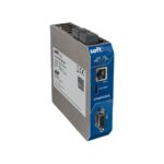
smartLink HW-PN is a product designed by Softing Industrial Automation GmbH for industrial automation applications.
Intended Use
The smartLink HW-PN is intended for use in industrial setting to facilitate communication and data exchange in automation systems.
Supported Features
The smartLink HW-PN supports features such as real-time clock, OPC UA, and FDI communications server.
System Requirements
Ensure that the system meets the technical data and hardware interface requirements specified for the smartLink HW-PN.
Product Usage Instructions
Installation
Follow the installation guidelines provided in the user manual for proper setup of the smartLink HW-PN in your industrial environment.
Restarting Factory Firmware
If needed, refer to the instructions on how to restart the factory firmware of the smartLink HW-PN for troubleshooting purposes.
Changing IP Address
Use the Search and Configure tool as described in Chapter 4 to change the IP address of the smartLink HW-PN.
Login to User Interface
Access the user interface of the smartLink HW-PN by logging in with the appropriate credentials for configuration and monitoring.
Configuring PROFINET
Refer to Chapter 4 for detailed instructions on configuring PROFINET settings on the smartLink HW-PN.
FAQs
- Q: Where can I find the latest documentation for the product?
- A: Scan the QR code provided or visit the product webpage under Downloads section for the most up-to-date documentation.
- Q: How can I obtain support or further information?
- A: Contact Softing Industrial Automation GmbH via the provided email addresses or visit their support webpage for assistance.
User Guide
smartLink HW-PN
Version: EN-082024-1.03
© Softing Industrial Automation GmbH
Disclaimer of liability
The information contained in these instructions corresponds to the technical status at the time of printing of it and is passed on with the best of our knowledge. Softing does not warrant that this document is error free. The information in these instructions is in no event a basis for warranty claims or contractual agreements concerning the described products, and may especially not be deemed as warranty concerning the quality and durability pursuant to Sec. 443 German Civil Code. We reserve the right to make any alterations or improvements to these instructions without prior notice. The actual design of products may deviate from the information contained in the instructions if technical alterations and product improvements so require.
Trademarks
PROFINET is a registered trademark of PROFIBUS Nutzerorganisation e.V. (PNO)
OpenSource
To comply with international software licensing terms, we offer the source files of open source software used in our products. For details see https://opensource.softing.com/ If you are interested in our source modifications and sources used, please contact: info@softing.com
Softing Industrial Automation GmbH Richard-Reitzner-Allee 6 85540 Haar / Germany https://industrial.softing.com
+ 49 89 4 56 56-340 info.automation@softing.com support.automation@softing.com https://industrial.softing.com/support/support-form
Scan the QR code to find the latest documentation on the product web page under Downloads.
Chapter 1 –
About this guide
1 About this guide
1.1 Read me first
Please read this guide carefully before using the device to ensure safe and proper use. Softing does not assume any liability for damages due to improper installation or operation of this product. This document is not warranted to be error-free. The information contained in this document is subject to change without prior notice. To obtain the most current version of this guide, visit the product website.
1.2 Target audience
This guide is intended for experienced operation personnel and network specialists responsible for configuring and maintaining field devices in process automation networks. Before installing and operating the smartLink HW-PN make sure that you have read and fully understood the safety requirements and working instructions in this guide.
1.3 Typographic conventions
The following conventions are used throughout Softing customer documentation:
Keys, buttons, menu items, commands and other elements involving user interaction are set in bold font and menu sequences are separated by an arrow
à à Open Start Control Panel Programs
Buttons from the user interface are enclosed in
Press [Start] to start the application
brackets and set to bold typeface
Coding samples, file extracts and screen output is set in Courier font type
MaxDlsapAddressSupported=23
Filenames and directories are written in italic
Device description files are located in C:
<Application name>deliverysoftwareDevice
Description files
CAUTION
CAUTION indicates a potentially hazardous situation which, if not avoided, may result in damage or injury.
Note
This symbol is used to call attention to notable information that should be followed during installation, use, or servicing of this device.
Hint This symbol is used when providing you with helpful user hints.
Version EN-082024-1.03
5
smartLink HW-PN – User Guide
1.4 Document history
Document version 1.00 1.01 1.02
1.03
Changes since last version
First version
§ Minor editorial changes § Chapter Resetting the device 18 added. § New Live List 44 features.
à § User interface chapters Settings Certificates 35 and OPC UA à Security 26 added.
1.5 Related documentation and videos
See the following links for additional and related product information:
§ Currently not applicable
1.6 Document feedback
We would like to encourage you to provide feedback and comments to help us improve the documentation. You can write your comments and suggestions to the PDF file using the editing tool in Adobe Reader and email your feedback to support.automation@softing.com. If you prefer to write your feedback directly as an email, please include the following information with your comments: § document name § document version (as shown on cover page) § page number
6
Version EN-082024-1.03
Chapter 2 –
About smartLink HW-PN
2 About smartLink HW-PN
The Softing smartLink HW-PN provides access to the communication system and connects the higher-level network structure with the field level. The default configuration allows for a start-up in only a few minutes. In order to prevent network disruptions by unauthorized configuration changes, all configuration functions are protected by user administration.
2.1 Intended use
The smartLink HW-PN is designed to be used as a secure access point to PROFINET networks. Any other use is deemed non-intended use.
CAUTION Do not use this device in hazardous areas! See Section Technical Data 8 for permissible ambient conditions.
Note Installation and operation of the smartLink HW-PN must be performed by qualified personnel only.
2.2 Supported features
smartLink HW-PN supports the following features: § access to PROFINET devices § access to Softing’s aplSwitch Field, pnGate PA and pnGate DP § PLC-independent access to PROFINET networks
2.3 System requirements
To parametrize PROFINET devices with your smartLink HW-PN you will need: § 18 VDC to 32 VDV power supply § PC with web browser § Ethernet cable § PROFINET cable
Version EN-082024-1.03
7
smartLink HW-PN – User Guide
2.4 Technical data
Hardware
Interfaces
Supported communication protocols Supported PROFINET PROFIBUS Proxies Dimensions (H x W x D) Weight Power Supply
Typical Power Loss Operating Temperature Storage Temperature Relative humidity Cooling Mounting Protection Altitude Usage location
Processor: Altera Cyclone V SoC with dual-core ARM Cortex-A9 Status LEDs: PWR, RUN, ERR, BUS Real-Time Clock: Real-Time clock with buffering, setting the time via browser or by NTP server (buffer time depends on conditions such as ambient temperature and duration of use) Ethernet: 1 x IEEE802.3 10BASE-T/100BASE-TX/1000BASE-T, Connector: RJ45 PROFINET: 2 x IEEE802.3 10BASE-T/100BASE-TX, Connector: RJ45 Embedded PROFINET 2-port switch for line or ring topology Protocol: PROFINET RT / IRT, Support of PROFINET redundancy protocols PROFINET, PROFIBUS, FDI communication server (OPC UA)
Softing: pnGate PA, pnGate DP, aplSwitch Field PA
120 mm x 28 mm x 110 mm about 430g 18 VDC … 32 VDC; SELV/PELV power supply mandatory, typical input current: 200 mA, maximum input current: 1 A (allowing for in-rush current at switch-on) 5 W -40 °C … +65°C (see also Section Installation Positions 16 ) -40 °C … +85 °C 10 % … 95 %, non-condensing Convection, no fan DIN rail 35 mm IP20 intended use must not exceed 2000 m in altitude indoor use only; no direct sunlight
8
Version EN-082024-1.03
2.5 Hardware interfaces
Chapter 2 – About smartLink HW-PN
2.5.1
Real-time clock
A real-time clock (RTC) is located on the device, which is used to validate the temporal validity when using certificates. The real-time clock is buffered so that the real-time clock continues to run in the event of a brief power failure. The buffer time is limited and depends on various parameters (ambient temperature, duration of use, …) and can range from a few hours to several days.
During the initial installation and if the power failure lasts longer than the buffer time, the RTC can be set using a browser via the web server (see corresponding section: Setting the RTC via browser).
Therefore, a problem with the validity of a certificate may indicate that the real-time clock is not set. It is recommended to use a time server in the network (NTP server), then the device automatically fetches the current time (see corresponding section: Activating the NTP server).
2.5.2
Safety precautions
CAUTION During operation, the device’s surface will be heated up. Avoid direct contact. When servicing, turn off the power supply and wait until surface has cooled down.
CAUTION
The electronic components of the smartLink HW-PN are sensitive to electrostatic discharges. Damages due to electrostatic discharge can lead to premature failure of components or intermittent faults at a later stage. Before installing the smartLink HW-PN, divert the electrostatic discharge away from your body and the tools used.
Note
Do not open the housing of the smartLink HW-PN. It does not contain any parts that need to be maintained or repaired. In the event of a fault or defect, remove the device and return it to the vendor. Opening the device will void the warranty!
2.6 Software interfaces
2.6.1
OPC UA
The smartLink HW-PN has an OPC UA server integrated. This server implements the TCP based binary OPC UA protocol and allows OPC UA clients to connect to it.
2.6.1.1
FDI communication server
The FDI communication server supports both PROFINET (FCG_TS62769-103-4) and PROFIBUS (FCG_TS62769103-1) profiles.
The OPC UA server of the smartLink HW-PN complies with the OPC 30080-7 / FCG TS62769-7 specification V1.3 “FDI Communication Devices”. This specification can be found on the FieldComm Group web page (www.fieldcommgroup.org) and for download on the OPC Foundation web page (www.opcfoundation.org).
An example of an FDI communication client written in Python is available at: https://github.com/SoftingIndustrial/FDICommClient.
Version EN-082024-1.03
9
smartLink HW-PN – User Guide
2.7 LED status indicators
smartLink HW-PN has four device status LEDs at the top, two connection status LEDs on the web server port and two on each PROFINET connection port:
PWR RUN ERR BUS

 = power supply – refer to next section 11 = running – refer to next section 11 = error – refer to next section 11 = configuration – displays configuration upload – refer to next section 11
The device status LEDs are permanently on or flash in different colors and frequencies as indicated below:
Symbol
Color none red green red red green green green orange (red/green) orange (red/green)
Light off permanent permanent flashing (1 Hz) flashing quickly (5 Hz) flashing (1 Hz) flashing slowly (0.5 Hz) flashing quickly (5 Hz) permanent green permanent + red flashing (1 Hz)
The Ethernet port LEDs indicate the following behaviour:
Ethernet port LEDs
Colour Behaviour
green ON when port has an active link
yellow FLASHING when there is traffic on the port
The PROFINET port LEDs indicate the following behaviour:
PROFINET port LEDs Colour Behaviour
green yellow
ON when port has an active link and FLASHING when there is traffic on the port
currently not in use
10
Version EN-082024-1.03
2.7.1
Status LEDs startup phase
LEDs
PWR RUN ERR
BUS
Chapter 2 – About smartLink HW-PN
Meaning Power Off check Power supply.
PWR RUN ERR
BUS
Power On – 24V DC power supply is ok.
PWR RUN ERR
BUS
Start up phase (up to 30 seconds).
PWR RUN ERR
BUS
Start up phase finished check execution mode (normal or factory).
2.7.2

Status LEDs factory mode
LEDs
PWR RUN ERR
BUS
Meaning Device running in factory mode.
PWR RUN ERR
BUS
Firmware update is running.
PWR RUN ERR
BUS
Request to execute factory reset.
PWR RUN ERR
BUS
Device executes factory reset.
PWR RUN ERR PWR RUN ERR
BUS
Software error – restart the device.
n.a
BUS
Software error – device restarted automatically and error is
reported in log file.
n.a
Version EN-082024-1.03
11
smartLink HW-PN – User Guide
2.7.3 Status LEDs normal mode
LEDs
PWR RUN
ERR
BUS
n.a.
n.a.
PWR RUN
ERR
BUS
n.a.
n.a.
PWR RUN
ERR
BUS
n.a.
PWR RUN
ERR
BUS
n.a.
PWR RUN
ERR
BUS
n.a.
PWR RUN
ERR
BUS
n.a.
PWR RUN
ERR
BUS
n.a.
Meaning Device running in Normal mode.
Firmware update is running.
Device is configuring for PROFINET.
Device joined PROFINET and is online.
Software error – restart the device.
Software error – device restarted automatically and error is reported in log file. Flash LED operation is running (DCP-Signal).
12
Version EN-082024-1.03
Chapter 3 –
Installation
3 Installation
3.1 Hardware installation
Note With an ambient temperature above 55 °C at the place of installation it is very likely that the temperatures of connecting cables will increase if the cables are installed in an unfavourable position. In such cases, measure the temperature to ensure that the service temperature of the cables is not exceeded or use cables sustaining high temperatures of at least 90 °C.
3.1.1
Mounting and dismounting
Note
Make sure the smartLink HW-PN is mounted in such a way that the power supply can be easily disconnected. Depending on the installation position, the maximum ambient operating temperature may differ. See Section Installation positions 16 for details.
Installation and inspection
Installation and inspection must be carried out by qualified personnel only (personnel qualified according to the German standard TRBS 1203 – Technical Regulations for Operational Safety). The definition of terms can be found in IEC 60079-17.
Mounting
1. Hook the upper notch of the cut-out on the back of the device into a 35 mm DIN rail.
2. Leverage the screwdriver upwards, pull the locking bar downwards and move the device down towards the rail.
3. Press the gateway down towards the rail until it slides into place over the lip of the locking bar.
Note
Do not put stress on the system by bending or torsion.
Dismounting
1. Slide a screwdriver diagonally under the housing into the locking bar.
2. Leverage the screwdriver upwards, pull the locking bar downwards and move the gateway upwards off the rail.
Version EN-082024-1.03
13
smartLink HW-PN – User Guide
3.1.2
Connections and nameplate

The following diagram shows the interfaces of the smartLink HW-PN. The device has one 1 GBit Ethernet port (ETH) connecting to your IT network and two 100 MBit Ethernet ports connecting to your PROFINET network and PLC. The connectors on the top are reserved for the supply voltage and alarm output. The uSD card slot is used for future service purposes and is not supported in the current version of the product.
14
Version EN-082024-1.03
3.1.3
Chapter 3 – Installation
Power and alarm connectors
Connect the smartLink HW-PN to a 24 V DC power supply. Note smartLink HW-PN is intended for connection to a SELV/PELV circuitry only.
Power connector
The supply voltage (18 VDC …. 32 VDC) is connected by a 3-pole terminal block. The power supply is connected to the plug connector via flexible wires with a cross section of 0.75 to 1.5 mm². The ground connection wire must have a cross section of 1.5 mm².
Signal 24VDC
Description 24 V DC power supply Functional earth
GND
Ground
CAUTION
The Functional Earth (FE) connection of the device has to be connected at low inductance with the Protective Earth (PE) of the system.
Alarm connector
The alarm output has a voltage range of 0-32V. Connect the positive supply voltage with the COM terminal to avoid damage when the connector accidentally mixed up.
Signal NO NC COM
Description Normally Open Normally Closed Common Terminal
Version EN-082024-1.03
15
smartLink HW-PN – User Guide
3.1.4
Installation positions
The smartLink HW-PN can be mounted horizontally and vertically. Depending on the installation position, different ambient operating temperatures (Ta) apply.
Minimum distance Provide a minimum distance of 50 mm to the air inlet and air outlet to ensure natural convection.
Rotated installation position The maximum permissible ambient temperature values also apply to a 180° rotated installation position.
Horizontal installation position
Vertical installation position
Max. ambient temperature (Ta) Ta – no distance
horizontal vertical
60 °C 50 °C
Ta at 28mm distance between devices 65 °C
60 °C
16
Version EN-082024-1.03
3.1.5
Chapter 3 – Installation
Connecting to the network

1. Connect your PC to the 1 GBit Ethernet (ETH) port of your smartLink HW-PN. 2. Connect your PROFINET network (with its Remote IOs, field devices and PLC) to the Ethernet ports
(ETH1 and/or ETH2) of your smartLink HW-PN .
Note The smartLink HW-PN can also be used in a PROFINET line or ring topology too. In this case it is best to locate it next to the controller.
Note To access PROFIBUS devices, the PROFINET-PROFIBUS proxies have to be in the same PROFINET network as the smartLink HW-PN .
3.1.6
Powering up the device
Turn on the power supply. The boot process will take about 30 seconds. Refer to LED status indicators 10 for a detailed description of the LEDs and their behaviour.
Version EN-082024-1.03
17
smartLink HW-PN – User Guide
3.1.7
Resetting the device
If your smartLink HW-PN is not responding, is malfunctioning or you simply cannot log on to the device because you have forgotten your login credentials you can restore the original factory conditions, remove the existing user data and clear the device settings by performing a hard reset. Licenses will not be affected by the reset and will remain on the device. However, performing a factory reset will clear your device of all parameter settings and configuration data.
Note We recommend to press the reset button only if you wish to clear your device of all configurations or if you have attempted all other methods of troubleshooting. Remember that the a hard reset will delete all device settings and data added by the user.
3.1.7.1 How to reset the device to factory default
1. Insert the tip of a metal pin, of a pen or the end of an unwound paper clip into the hole of the reset button as shown.
2. Press the reset button very carefully while reconnecting and powering up the device again and hold the button until the RUN LED 11 turns red and is flashing fast.
3. Release the reset button. The smartLink HW-PN is restarting.
4. Press the reset button and hold for about 15 seconds until the two LEDs in the middle (RUN and ERR) are flashing red.
5. Release the reset button. When the lights turn off (after about a minute), the smartLink HW-PN is reset and starts in factory mode. First the PWR LED turns yellow. Next the PWR LED turns from yellow to green and the LED RUN turns from red to green.
6. Now update the device with the latest firmware. See Chapter Firmware update 32 for details.
18
Version EN-082024-1.03
Chapter 3 – Installation
3.1.7.2
How to restart the factory firmware
The smartLink HW-PN device comes with a factory firmware that cannot be deleted or overwritten. When the device detects that the standard user firmware is faulty, it will automatically resort to the factory firmware. However, in the unlikely event that the factory firmware is flawed and the smartLink HW-PN device does not manage to load it automatically, you will have to restart it manually by performing as described below. Licenses will not be affected by the reset and will remain on the device.
1. Disconnect the power supply from the smartLink HW-PN device.
2. Insert the tip of a metal pin, of a pen or the end of an unwound paper clip into the hole of the reset button as shown above.
Version EN-082024-1.03
19
smartLink HW-PN – User Guide 3. Press the reset button very carefully while reconnecting and powering up the device again and hold the button until the RUN LED 11 turns red and is flashing fast. 4. Release the reset button. The smartLink HW-PN is restarting. 5. Open your Internet browser and enter the IP address of your smartLink HW-PN to access the user interface. At this point the user interface indicates that it is running in factory mode.
à 6. Select Settings Choose Firmware File… to update the firmware of your smartLink HW-PN . See Chapter Firmware update 32 for details.
20
Version EN-082024-1.03
Chapter 3 – Installation
3.2 Software installation
3.3 Commissioning
The smartLink HW-PN comes with an integrated web server which is used to configure the device. The default IP address of the integrated web server is 192.168.0.10. To change the network settings of the smartLink HW-PN you can either change the IP address of the corresponding network adapter on your PC to access the integrated web server or use the Search and Configure tool. Section 4.2 21 and Section 4.3 23 describe how to perform either of these two settings.
3.3.1
Prerequisites
§ The smartLink HW-PN is connected with a PC which runs a Chrome, Microsoft Edge or Firefox web browser supporting JavaScript.
3.3.2
Changing the IP address using the integrated web interface
You can access the web interface of the smartLink HW-PN by changing the IP address of your PC. Using the web interface you can change the network settings of the smartLink HW-PN afterwards.
The following chapter describes how to set a static IP address in Windows 10.
1. Click Start Windows System Control Panel from your task bar.
2. Select Network and Internet Network and Sharing Center. A new window opens where you can view your basic network information.
3. Click on your Internet connection (either Ethernet or wireless) next to Connections under View your active networks. A new window opens.
4. Click [Properties].
5. Select Internet Protocol Version 4 (TCP/IPv4). The following window opens.
Version EN-082024-1.03
21
smartLink HW-PN – User Guide
6. Select Use the following IP address and enter a specific IP address and Subnet mask. In our example
we use the following settings:
IP address:
192.168.0.1
Subnet mask:
255.255.255.0
7. Click [OK] to confirm.
8. Adapt the network settings of your smartLink HW-PN as described in Section Network 29 .
3.3.3
Search and Configure Tool
You can optionally install the Search and Configure Tool on a Windows PC. This tool detects installed smartLink HW-PNs in a network and allows you to configure their network settings.
When you install a Softing product for the first time, you will be asked if you trust the publisher. Activate the option Always trust software from Softing AG if you do not want to be asked in subsequent installations and select [Install] to start the installation.
1. Go to the product website to download the latest Search and Configure*.
2. Start by downloading and installing the Search and Configure tool.
3. Follow the on-screen installation instructions.
4. Read the license agreement carefully. If you have questions, you can [Cancel] the installation at this point and contact us. Click [Print] if you want to print the license agreement to a PDF or on a printer.
5. Select I accept the terms in the license agreement and click [Next].
6. Click [Install] to install the selected software application on your PC. While the installation is in progress, the status bar of the installation wizard shows the different steps that are being executed. If you want to abort the installation, click [Cancel] button. The installation wizard will undo all modifications that have been made to your computer up to this point. Otherwise, wait until the installation is completed.
7. Press [Finish] to complete the installation and exit the wizard.
Note Proceed with the installation of the other software packages.
___________
* Search and Configure: discovery and IP-Configuration of smartLink HW-PN
22
Version EN-082024-1.03
3.3.4
Chapter 3 – Installation
Changing the IP address using the Search and Configure tool
Before you can operate the connected smartLink HW-PN you will have to change the default IP address of your gateway so that your PC can communicate with the integrated web server over the Local Area Network.
The following steps apply to Windows 10.
à à 1. Click Start Softing Search and Configure.
The application window is opened.
2. Click the dropdown list of the Network Adapter Selection. This selection menu shows all network adapters of your PC.
3. Select the network adapter which is connected to the smartLink HW-PN.
4. Click [Search] to start searching for connected devices. The search may take a moment.
5. Select the smartLink HW-PN.
6. Click [Configure] or double-click the device. The configuration window opens. Here you can change the IP settings.
Version EN-082024-1.03
23
smartLink HW-PN – User Guide
Note You may also change the hostname. However, ensure that you follow hostname specifications RFC 952 and RFC 1123.
7. Enter a dedicated IP address and subnet mask or click Use DHCP to obtain the IP settings from a DHCP server.
8. Enter the Password. Example: GEA-YA-026010<serialnumber> The serial number can be found on the device, on the packaging and in the Search and Configure tool. See Section Login to user interface 25 for details.
9. Click [Submit]. The changed settings are written to the device.
24
Version EN-082024-1.03
Chapter 3 – Installation
3.3.5
Login to user interface
1. Open your Internet browser and enter the IP address of your smartLink HW-PN.
2. Enter administrator in the user field and the password below (example: GEA-YA026010<serialnumber>). The default password (initial or after executing a factory reset) is a combination of the article number and the serial number which you find on the nameplate on the side of the device.
The web-based interface opens with the information page.
3.3.6
Configuring PROFINET
See Section PROFINET 49 in Chapter Working with the user interface for more details.
Version EN-082024-1.03
25
smartLink HW-PN – User Guide
4 Security
The smartLink HW-PN is installed in level 0 of the Purdue reference model. With its three Ethernet ports it resides in 2 network segments: § The upper Ethernet port ETH is providing Software interfaces for asset management applications
running in level 3. § The PROFINET Ethernet ports (ETH1 / ETH2) it must be part of the level 0 PROFINET network
segment.
smartLink HW-PN upper Ethernet (ETH) services
Service OPC UA
HTTP HTTPS
Port 4840 | TCP
80 | TCP 443 |TCP
Description OPC UA Server Only this port of the device should be accessible from level 3 HTTP Server of integrated web server HTTPS Server of integrated web server
26
Version EN-082024-1.03
Chapter 5 –
Working with the smartLink HW-PN
5 Working with the smartLink HW-PN
See Section Log in to user interface 25 for details on how to access the interface.
5.1 User interface
5.1.1
General functions
All interface windows display the following functions:
Restart Device
This function is available only when logged in as administrator or maintenance engineer and is used to restart the gateway remotely as instructed in this user guide or whenever required in ongoing operation.
Logout
Select this function to log out as an active user.
Auto logout
This default setting logs out the current user from the gateway if the interface has been inactive for 10 minutes.
5.1.2
Information
The Information window shows detailed product-related information in the menus System, License and About, including the type of gateway hardware, version, bootloader and firmware of your gateway.
5.1.2.1 System
à Select Information Device/System to view the hardware and software details of your device.
Version EN-082024-1.03
27
smartLink HW-PN – User Guide
Parameter Serial Number Firmware Version Bootloader Version Factory Version Hardware Version System ID Host ID
Meaning Serial number of the gateway. Version of the currently running firmware. Version number of the boot loader. Version number of the factory image. Version number of the hardware. device type = smartLink HW-PN This is the ID you will need to request a licence.
5.1.2.2
License
à Select Information License to view the licenses used by the gateway firmware under an open source
license.
5.1.2.3 About
à Select Information About to show information about Softing and other useful information.
28
Version EN-082024-1.03
Chapter 5 – Working with the smartLink HW-PN
5.1.3 Settings
5.1.3.1 Network
à Select Settings Network to view and change the TCP/IP settings.
Note You need to be logged in as Administrator or Maintenance 30 to change default settings. If you change the settings you must restart the gateway.
Parameter Obtain IP address from a DHCP server
IP address
Subnet mask Default gateway Hostname Enable discover services
Apply
Meaning
The Dynamic Host Configuration Protocol (DHCP) is activated and the IP address is obtained from a DHCP server.
Internet Protocol (IP) address of the device used for web access.
Subnet mask of the device used for web access.
Default gateway of the device used for web access.
Name of the device used by a name server.
Check the box to enable Simple Service Discovery Protocol (SSDP) multicast DNS (mDNS) and SearchAndConfigure.
Click [Apply] to confirm changes made in this window.
Version EN-082024-1.03
29
smartLink HW-PN – User Guide
5.1.3.2
User accounts
In this section you will learn how to change accounts and passwords.
à 1. Select Settings User Accounts.
As administrator you can create and delete user accounts and also change passwords.
2. Select a user role in the dropdown menu, assign a user name and enter a New password in the corresponding fields according to the password rules.
3. Retype the password in the Confirm new password field and click [Create] to save the user and password settings.
Password rules
A password must contain between eight and 128 characters, including at least 1 lower case letter, 1 upper case letter, 1 number and 1 special character: !”#$%&'()*+,-./:;<=>?@[]^_`{|}~
Changing the password
1. Enter the user name of the account for which you want to change the password. 2. Enter the Old password. 3. Enter the New password. 4. Retype the password in the Confirm new password field and click [Change] to save the new
password settings.
30
Version EN-082024-1.03
Chapter 5 – Working with the smartLink HW-PN
Deleting an account
1. Enter the user name of the account which you want to delete. 2. Click [Delete] to erase the account settings and all remove the user.
The following table shows the user roles and corresponding permissions:
Permission Create and delete accounts Change all passwords Change own password Configuring gateway Reading configuration Reading diagnostics Updating firmware Resetting gateway Installing HTTPS certificates
Administrator
þ þ þ þ þ þ þ þ þ
Diagnostic
þ þ þ þ þ þ þ þ þ
Maintenance
þ þ þ þ
Observer
þ þ þ
Note
The user role Diagnostic is not required for daily operations. It is reserved for internal purposes such as troubleshooting. Softing Support may ask you to add a user with this role to obtain more details of your smartLink HW-PN.
Version EN-082024-1.03
31
smartLink HW-PN – User Guide
5.1.3.3
Firmware
The gateway comes with pre-installed firmware which is maintained and updated to continuously enhance the functionality of the device. To ensure that your smartLink HW-PN is running the latest firmware version check for the latest version in the Softing Download Center. Bear in mind that the smartLink HW-PN cannot be downgraded to a previous version.
Note You need to be logged in as administrator 30 .
1. Download the firmware update to your computer. When you are downloading from this site for the first time you will have to register yourself in a few steps.
2. Log on to the web server of the smartLink HW-PN.
à 3. Select Settings Firmware in the side bar navigation.
4. Click [Choose Firmware File…] and select the file smartLink HW-PN V1-02.bin from the firmware update you downloaded.
5. Click [Update] to install the latest firmware and [OK] in the message window. The update progress is shown beneath the update button.
Hint Click [Check] to verify, if the file you have chosen is a valid firmware file.
32
Version EN-082024-1.03
Chapter 5 – Working with the smartLink HW-PN
The system performs a firmware file check. The download starts automatically. When the download is completed the smartLink HW-PN will be rebooted. When the boot process is completed, the RUN LED is ON.
Note After the gateway has rebooted you are automatically forwarded to the login page. If this fails press F5 to reload the web page. Note If anything goes terribly wrong during the firmware update you can always repeat the firmware update.
Version EN-082024-1.03
33
smartLink HW-PN – User Guide
5.1.3.4 Reset Unlike the factory reset (hard reset) described in Chapter Hardware Installation 9 , this soft reset deletes the configuration of your smartLink HW-PN and restores the factory settings of your gateway.
à 1. Select Settings Reset in the side bar navigation
2. Select [Erase Configuration] to reset your device to default settings. Note You need to be logged in as administrator 30 .
3. Click [OK] to confirm your selection. Your smartLink HW-PN will be restarted with the default settings. License files and IP settings will not be deleted.
Note The password is reset to the default password 25 .
34
Version EN-082024-1.03
Chapter 5 – Working with the smartLink HW-PN
5.1.3.5
Certificates
A certificate is a digital document that is needed to identify and authenticate a website or server and to establish a secure communication (HTTPS) with the OPC UA server of the smartLink HW-PN.
à Select Settings Certificates to see the smartLink HW-PN X.509 server certificate and load issuer
certificates which are used to validate the server certificate. The tables display the subject name and the expiration timestamp of the server and the issuer certificates. The first column either shows a checkmark indicating the certificate’s status ( = valid, = expired/not valid).
In the Server Certificate section you can create a new self-signed certificate, upload a new certificate and download the currently installed server certificate or a Certificate Signing Request (CSR). The downloaded server certificate can be passed on to the OPC UA client application to enable secure communication. The CSR can be forwarded to a Certificate Authority (CA) which may create a matching signed server certificate.
If you create a new self-signed certificate or change the existing server certificate, a pencil icon is shown in the right-most column of the server certificate list (see screenshot below). The icon indicates that the certificate settings have been changed but have not yet been applied and still need to be executed by clicking [Apply] in the top right corner.
In addition, intermediate issuer certificates can be uploaded to the Issuer Certificates section to configure a chain of trust for the issuer specified in the server or other intermediate certificates.
Note Ensure that the clock on the smartLink HW-PN is properly set. Otherwise this could result in
à the creation or usage of certificates that have already expired. See Settings Time & date for
details.
Note Your changes are not executed immediately but have to be confirmed by clicking [Apply] in the top right corner of the page. This will restart the OPC UA server component of smartLink HWPN. Any clients connected at that time will lose their connection but typically will automatically reconnect.
Version EN-082024-1.03
35
smartLink HW-PN – User Guide
5.1.3.6
Time & date
à Select Settings Time & Date in the side bar navigation to set the time and date of your your smartLink
HW-PN.
1. Click [Set time from browser] to synchronize the gateway with the PC date and time manually.
2. Click [Use time server] and enter the IP address of your time server to synchronize date and time automatically.
Parameter Browser time (UTC) Device time (UTC) NTP server
Time server
Meaning The time set on the PC. The time set on the gateway. IP address of a Network Time Protocol (NTP) server used for time synchronisation. The time can be set either manually or using a time server.
36
Version EN-082024-1.03
Chapter 5 – Working with the smartLink HW-PN
5.1.3.7
Licensing
Licenses are needed for PROFINET Device Support by any Asset Management Tool to parametrize and monitor PROFINET devices and to retrieve process data and diagnosis data via OPC UA. Each license is tied to one PROFINET slave and can be used for Asset Management and for OPC UA at the same time.
You will most likely have purchased your smartLink HW-PN with one or more PROFINET licenses installed. You will need a license for each field device to which you wish to connect over the PROFINET network. A license is a unique key tied to the serial number of your gateway. It cannot be migrated or run on another smartLink HW-PN.
If your smartLink HW-PN has no license or you wish to connect to more PROFINET devices than previously licensed, please contact Softing Support.
How to activate a license
1. Go to the Softing Industrial website and click the icon in the upper right corner to register yourself or select this My Softing Portal link. When you are registered and logged in you are directed to the My Softing Dashboard.
à 2. Select Licenses Activate License in the side menu.
3. Enter the license key from your License Certificate in the license key input field. You will find the license key on the certificate you have received by email.
Version EN-082024-1.03
37
smartLink HW-PN – User Guide
à 4. Select Information System 27 .
5. Highlight and copy the Host ID from the Device/System table.
6. Paste the Host ID into the Host ID field of the Activate License form.
7. Click [Activate License]. A license file is generated and downloaded to your PC. Note The license file is assigned to the device and can therefore only be used with this device.
38
Version EN-082024-1.03
Chapter 5 – Working with the smartLink HW-PN
How to install a license
To install a license file follow these steps:
à 1. Select Settings Licensing in the side bar navigation.
2. Click the [Choose License File] button. Windows Explorer (file explorer) will open.
3. Go to the directory to which you have saved the file. 4. Select the license file and click [Open] in Windows Explorer.
The license file is now shown under the [Choose License File] button. 5. Click the [Install] button.
When the license has been installed, the following message appears at the bottom of the window.
In the Licensing window, the table entries for PROFINET Device Support will have changed.
Parameter Version Options End date Description
Meaning A support number (for internal use only). Total number of supported PROFINET devices. The date on which the license expires. Generally all licenses are unlimited. Before a license is installed, this field displays the order number for a license for this specific gateway.
Version EN-082024-1.03
39
smartLink HW-PN – User Guide
Status
Before a license is installed, this field displays “not installed”. When a license has been installed it shows “restart required” against a yellow background. After the gateway has been restarted it shows “installed” against a green background
6. Click Restart Device in the top menu of the window. The following message will appear.
7. Click OK. Now the status column will show “installed” meaning the license is activated on your smartLink HWPN device.
40
Version EN-082024-1.03
5.1.4
Chapter 5 – Working with the smartLink HW-PN
Diagnosis
Note The submenus Settings, Log File, Threads and Status are of particular interest for Softing Support.
5.1.4.1
Settings
à Select Diagnosis Settings to view logging settings. The settings can be viewed in any role. To change the
settings you must have administration rights.
Parameters/Actions Log File Priority
Log File Facility Send Syslog Messages
Syslog Priority
Syslog Facility Apply
Meaning
Available values: EMERGENCY, ALERT, CRITICAL, ERROR, WARNING, NOTICE, INFORMATION. All messages with the set priority or higher
are logged. The log file is shown under Diagnosis à Log File
Tick the checkbox for the protocol layer you wish to write to the log file.
Enables additional Log File Priority DEBUG and sends the information to the network. The syslog can be logged with wireshark, Visual Syslog Server or similar.
Available values: EMERGENCY, ALERT, CRITICAL, ERROR, WARNING, NOTICE, INFORMATION. All messages with the set priority or higher are logged.
Tick the checkbox for the protocol layer you wish to write to the syslog file.
Click [Apply] to save your changes in the system. If you do not click apply the changes will not be saved.
Version EN-082024-1.03
41
smartLink HW-PN – User Guide
5.1.4.2
Log File
à Select Diagnosis Log File to view the log file. You can also filter the diagnostic log by ticking and
unticking the checkboxes for each notification priority. Filtering only affects the display of the log and not
à the log file priority set under Diagnosis Settings.
Note
If you are facing problems with your smartLink HW-PN, use the button [Support Data] to create a support file. The information contained in this file helps Softing Support address and fix potential issues.
Parameters / Actions
Meaning
EMERGENCY; ALERT, CRITICAL, Tick the check boxes to set a display filter. ERROR, WARNING, NOTICE, INFORMATION, DEBUG
Clear
Click this button to delete the log file entries.
Refresh
Click this button to update the message log entries based on the filter settings.
Support Data
Click this button to upload a collection of all available logs for support requests.
42
Version EN-082024-1.03
Chapter 5 – Working with the smartLink HW-PN
5.1.4.3
Threads
à Select Diagnosis Threads to view the current state of the threads. The list you will see and the details
contained may not be of any use to you but helps Softing support to diagnose device and performance
errors.
5.1.4.4 Status
à Select Diagnosis Status to view gateway diagnostics.
Version EN-082024-1.03
43
smartLink HW-PN – User Guide
5.1.4.5
Live List

à Select Diagnosis Live List to see a table with all PROFINET, APL and PB devices connected to Softing APL
switches, pnGate PA or pnGate DP devices. The table is organized top-down in blocks from general status
information to PROFINET and PROFIBUS devices details.
u Results of the last scan: The general information includes the timestamp and the duration of the last completed scan, the total number of detected and licensed devices and the number of remaining licenses.
v Summary of PROFINET scans: This header represents the number of detected and licensed PROFINET devices. PROFINET device details can be hidden and displayed by clicking the arrow icon ( ) to the left of the header text. If the PROFINET communication is not working correctly or an error occurred while scanning one of the PROFINET devices, the Status shows an error icon .
w Details of PROFINET scans: The table lists the characteristic device properties such as name, type, function, location, IP address or MAC address. If a scanned device has an error, this is indicated by an error icon in the leftmost column and an error message displayed in Status field. The PROFIBUS icon ( ) in the Type column indicates that the device has a PROFIBUS segment. By clicking the icon the corresponding proxy section and PROFIBUS device table is displayed.
x Summary of PROFINET-to-PROFIBUS proxy scans: This header sums up the number of detected and licensed PROFIBUS devices. If a child component (any underlying PROFINET-to-PROFIBUS proxy) shows an error this is indicated in the header information.
y Details of proxies: The header view shows all proxies with a PROFIBUS segment.
44
Version EN-082024-1.03
Chapter 5 – Working with the smartLink HW-PN
z Details of PROFIBUS devices: The table includes all successfully scanned PROFIBUS devices with additional properties such as channel number, tag function and location, vendor, device type, hardware and software revision numbers, status. To the left of the device name you may see one of the following icons:
{ = device is licensed and = error occurred during scan of the PROFIBUS device Reassign licenses By clicking [Reassign Licenses] you can reassign all available licenses. This will entail a restart of your smartLink HW-PN
Scan progress bar (%) Indicates the progress of a running scan process.
Start Scan A scan is started cyclically once per minute. By pressing this button you can invoke a manual scan. When a scan is in progress this button is disabled.
| Collapse All Hides all tables with details of connected PROFIBUS devices.
Expand All Expands all tables with details of connected PROFIBUS devices.
Version EN-082024-1.03
45
smartLink HW-PN – User Guide
PROFINET table column headers explained
Column Header Name Type
Tag Function Tag Location Address
MAC Address
Vendor
Device Type HW Revision SW Revision Status
Meaning The device name of the PROFINET device Indicates if the PROFINET device has a proxy functionality. If so, a corresponding icon is displayed. By clicking on the icon you are navigated to the corresponding proxy section. Displays the Tag Function contained in the device.
Displays the Tag Location contained in the device. The Internet Protocol Address is a set of four numbers separated by periods identifying a device in your network. The Medium Access Control Address is the unique 12-digit hexadecimal device number assigned by device manufacturer. This column displays in brackets the manufacturer Identification code as a hexadecimal value. A vendor name is shown only if this value can be resolved. Displays the type of the PROFINET device as a hexadecimal value. Displays the hardware revision of the PROFINET device. Displays the software revision of the PROFINET device. It is either shown as “OK” (when a PROFINET device has been successfully scanned) or with a red error text describing the error detected during the scan process.
PROFIBUS table column headers explained
Column Header Address Tag Function Tag Location Vendor
Device Type
HW Revision SW Revision Status
Meaning Displays the address of the PROFIBUS device. Displays the Tag Function contained in the device. Displays the Tag Location contained in the device. This column displays in brackets the manufacturer Identification code as a hexadecimal value. A vendor name is shown only if this value can be resolved. Displays the type of the PROFIBUS device as a hexadecimal value in brackets. A device type name is shown if this value can be resolved. Displays the hardware revision of the PROFIBUS device. Displays the software revision of the PROFIBUS device. It is either shown as “OK” (when a PROFIBUS device has been successfully scanned) or with a red error text describing the error detected during the scan process.
46
Version EN-082024-1.03
5.1.5
Chapter 5 – Working with the smartLink HW-PN
OPC UA
All FDI-related instances have a NodeId with a string identifier. These are located in the OPC UA server application name space index 1.
5.1.5.1
Identity
à Select OPC UA Identity to see the server endpoint. In the current version of the smartLink HW-PN the
server endpoint has the default port 4840, which cannot be changed in the user interface.
5.1.5.2
Security
à Select OPC UA Security to configure a secure communication between the smartLink HW-PN (OPC UA
server) and the OPC UA client application.
In the Security Configuration window frame, smartLink HW-PN offers three encryption modes supported by three security policies for secure OPC UA communication:
Version EN-082024-1.03
47
smartLink HW-PN – User Guide
If you have changed any of the security configuration setting, a pencil icon is shown to indicate that the settings have been changed but have not yet been applied and the the changes still need to be executed by clicking [Apply] in the top right corner.
Message Security Meaning Modes
None
Don’t use any encryption. No certificate exchange is needed between smartLink HW-PN and a client. Be aware that communication on the network is readable by others. This might be a security risk.
Sign
Messages sent from smartLink HW-PN or the OPC UA client are signed with the private
key of the sender. The receiving entity can validate the origin of the message using the
public key of the sending entity. Nevertheless, messages are not encrypted.
Sign and Encrypt
Message are signed as in the Sign mode and additionally encrypted with the public key of the receiving entity. On the receiver side the message can be decrypted using its private key.
If you check None, no security policy must be selected. For the modes Sign and/or Sign and Encrypt at least one policy must be chosen. Although any combination of modes and policies is possible, it is recommended to restrict the configuration to the one that the OPC UA client application is expected to use. For further details see the documentation of the client application.
To establish a secure OPC UA communication smartLink HW-PN and the OPC UA client application have to exchange their public keys. For this they store a certificate of the communication partner in their Public Key Infrastructure (PKI). The OPC UA client application typically receives the public key of smartLink HWPN by calling the OPC UA service GetEndpoints. Alternatively, it can be exported from smartLink HW-PN
à à à (Settings Certificates Server Certificate Download) and imported manually in the client
application. See also the OPC UA client application documentation for more information on how to store the smartLink HW-PN certificate in the Trusted section of its PKI.
The Certificate Management window frame shows all certificates that are trusted or have been rejected (as a result of a unsuccessful connection attempt from the client application). When an OPC UA client application attempts to open a secure connection to a smartLink HW-PN it submits its client certificate. smartLink HW-PN stores this certificate in the Rejected Client Certificates table (see screenshot above). Before a connection between the smartLink HW-PN and the client can be established you have to confirm that you trust this certificate. If the certificate is available as a file, you may upload it directly to the Trusted Client Certificates.
The tables include the subject name and the expiration timestamp of each certificate. The first column either shows a checkmark indicating that the certificate’s status ( = valid, = expired/not valid). You can upload new or delete existing client certificates to the Trusted Client Certificates and move client certificates from the Rejected Client Certificates table the Trusted section or simply delete them from the PKI.
Note
Your changes are not executed immediately but have to be confirmed by clicking [Apply] in the top right corner of the page. This will restart the OPC UA server component of smartLink HWPN. Any clients connected at that time will lose their connection but typically will automatically reconnect..
48
Version EN-082024-1.03
Chapter 5 – Working with the smartLink HW-PN
For a detailed view of the common client certificate properties, select and highlight a certificate in either table as shown in the sceenshot above (example certificate: ctt_appT).
5.1.6
PROFINET
à 1. Select PROFINET Settings to enter the IP settings of your PROFINET network.
2. Click [Apply] to confirm and activate your settings. 3. Select Restart Device in the menu bar to active the new IP settings.
Version EN-082024-1.03
49
smartLink HW-PN – User Guide
6 Declaration of conformity
This device is compliant with EC directive 2014/30/EG, “Electromagnetic Compatibility” (EMC directive) and meets the following requirements:
§ EN 55011
Industrial, scientific and medical (ISM) devices – radio disturbance limits and methods of measurement
§ EN 55032
Electromagnetic compatibility of multimedia equipment (MME) and interference emission
§ EN 61000-6-4
Electromagnetic compatibility (EMC); Part 6-4: generic standard emission for industrial environments
§ EN 61000-6-2
Electromagnetic compatibility (EMC); Part 6-2: generic standard immunity for industrial environments
Note To fulfill the EMC requirements, the other components of your installation (DC adapter, Industrial Ethernet devices, etc.) also have to meet the EMC requirements. A shielded cable must be used. In addition, the cable shield must be grounded properly.
CAUTION This is a Class A product. In a domestic environment this product may cause radio interference in which case the user may be required to take adequate measures!
CE The CE marking indicates conformity with the above standards in a Declaration of Conformity which can be requested from Softing Industrial Automation GmbH.
RoHS This product is compliant the Restriction of Hazardous Substances under Directive 2002/95/EC.
FCC This equipment has been tested and found to comply with the limits for a Class A digital device, under part 15 of the FCC Rules. These limits are designed to provide reasonable protection against harmful interference when the equipment is operated in a commercial environment. This equipment generates, uses, and can radiate radio frequency energy and, if not installed and used in accordance with the instruction manual, may cause harmful interference to radio communications.
VCCI This Class A product conforms to the regulations of Voluntary Control Council for Interference (VCCI) by Information Technology Equipment.
WEEE Electrical and electronic equipment must be disposed of separately from normal waste at the end of its operational lifetime in compliance with Waste Electrical & Electronic Equipment (WEEE) Directive 2002/96/EC. Packaging material and worn components shall be disposed of according to the regulations applicable in the country of installation.
50
Version EN-082024-1.03
7 Glossary
Abbreviations CA CSR DHCP DIN DP ETH Ex FDI GND HTTPS I/O IP NTP OPC UA PA PKI PLC PN pnGate RIO RTC T
Chapter 7 – Glossary
Definition Certificate Authority Certificate Signing Request Dynamic Host Configuration Protocol Deutsches Institut für Normung Decentralised Peripherals Ethernet Explosion protection Field Device Integration Ground Hypertext Transfer Protocol Secure Input/Output Internet Protocol Network Protocol Time Open Platform Communications Unified Architecture Process Automation Public Key Infrastructure Programmable Logic Controller PROFINET Softing PROFINET Gateway Remote Input / Output real-time clock Temperature
Version EN-082024-1.03
51
Softing Industrial Automation GmbH
Richard-Reitzner-Allee 6 85540 Haar / Germany https://industrial.softing.com
+ 49 89 45 656-340 info.automation@softing.com
Documents / Resources
 |
Softing smartLink HW-PN Gateway for Asset Management [pdf] User Guide smartLink HW-PN Gateway for Asset Management, smartLink HW-PN, Gateway for Asset Management, Asset Management |