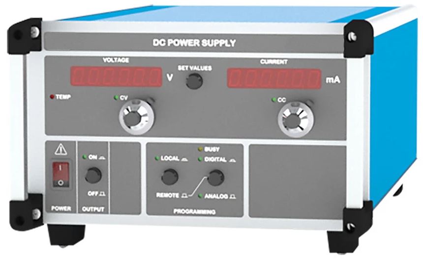
XP Power Isolated Analog interface
Product Specifications
- Analog interface options
- AC-HVDC power supplies
- Wiring options: Controllable with semiconductors or switches
Product Usage Instructions
Analog Interface Options:
- The analog interface (15-pole D-sub socket on the rear panel) is used for controlling voltage setting, current setting, OUTPUT ON/OFF, and special functions depending on the unit type.
- Current actual values are provided as analog voltages, and the latest control modes are digital signals.
- Analog programming can be installed later for most models at the site.
AC-HVDC Power Supplies:
Power supplies are available in non-isolated, isolated, and floating (max 600V) configurations.
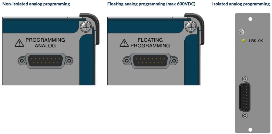
Programming Options:
- Non-isolated Analog Programming
- Floating Analog Programming (max 600VDC)
- Isolated Analog Programming
Control Output Variants:
- 0 – 10V (Standard)
- 0 – 10V (for PLC)
- 0 – 5V
- 4 – 20mA
Front Panel:
Control unit with selectable operating modes: LOCAL / ANALOG / DIGITAL programming.
Rear Panel:
D-Sub 15-pin interface with pin assignments for various functions.
Wiring Options:
Can be controlled with semiconductors or switches using different wiring configurations.
The analog interface (15-pole D-sub socket on the rear panel) is used to control the functions voltage setting, current setting as well as OUTPUT ON/OFF and, depending on the unit type, special functions. The current actual values are provided as analog voltages and the latest control modes as digital signals.
For most models, the analog programming can be installed later at our site.
Analog programming
| Description | Control output variants | |
| Non-isolated | Due to the direct coupling of the analog signals, the device characteristics like accuracy, linearity, stability, and temperature coefficient remain unchanged.
Please note that the power supply units which are equipped with the non- isolated analog programming option CANNOT be operated potential-free! |
0 – 10V (Standard) 0 – 10V (for PLC) 0 – 5V 4 – 20mA |
| Isolated | All signals are 2kV isolated from the output potential via fiber optic.
With isolated analog programming there is no galvanic connection between the pins of the programming interface and the output sockets. On request, we can also supply a fiber optic option with isolation capabilities up to 200kV and more. |
0 – 10V (Standard) |
| Floating (max 600V) | The analog signals for voltage and current setpoint as well as voltage and current monitors are isolated from the output potential via isolation amplifiers.
Digital signals are isolated via optocouplers. Floating analog programming has the advantage of faster data transmission compared to isolated analog programming. |
0 – 10V (Standard) 0 – 10V (for PLC) |
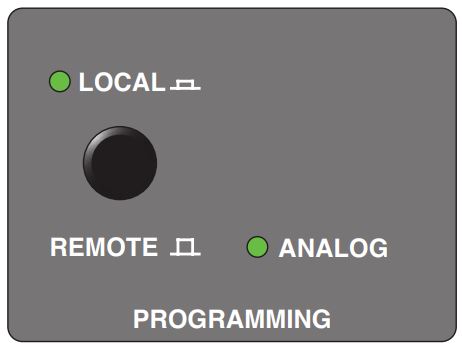
Front panel
Control unit with two selectable operating modes:
LOCAL / ANALOG programming.
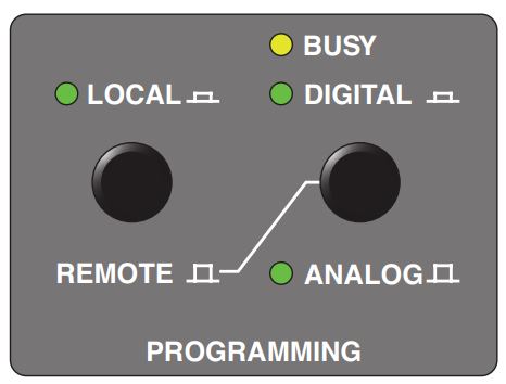
Control unit with three selectable operating modes:
LOCAL / ANALOG / DIGITAL programming.
Rear panel
D-Sub 15-pin interface
The assignment of some pins differs depending on the device series.
The plug connection is shown from its solder side.

| Pin | Description | Type(2) | Function |
| 1 | CC | DO | Supplies approximately +15V, if the power supply is in constant current mode, equivalent to LED CC, Ri approximately 10k Ω |
| 2 | CV | DO | Supplies approximately +15V, if the power supply is in voltage mode, equivalent to LED CV, Ri approximately 10kΩ |
| 3 | I-MON | AO | Actual output current monitor signal 0…10V, represents 0…Inominal, Ri approximately 10kΩ |
|
4 |
VPS |
AO |
Only used for a non-isolated analog programming interface.
Slider voltage pot on front panel 0…+10V, Ri approximately 10kΩ |
|
5 |
IPS |
AO |
Only used for a non-isolated analog programming interface.
Slider current pot on front panel 0…+10V, Ri approximately 10kΩ |
| 6 | 0VD | D GND | Ground for digital signals. May be currently loaded. |
| 7 | The function of this pin depends on the power supply series. | ||
| 8 | V-SET | AI | 0…+10V equals 0…Unominal, input resistance to 0V approximately 10mΩ |
| 9 | 0V | A GND | Ground for analog signals. Must not carry any current. |
| 10 | +10VREF | AO | +10V reference (output), max. 2mA |
| 11 | V-MON | AO | Actual output voltage monitor signal 0…10V represents 0…Unominal; Ri approximately 10kΩ |
|
12 |
OUTPUT ON |
DI |
Pin (12) open = OUTPUT OFF
Pin (12) connected to 0VD Pin (6) = OUTPUT ON |
| 13 | The function of this pin depends on the power supply series. | ||
| 14 | Not used | ||
| 15 | I-SET | AI | 0…+10V equals 0…Inominal, input resistance against 0V is approximately 10mΩ |
Notes:
- All values of voltages and currents are in DC.
- D=Digital, A=Analog, I=Input, O=Output, GND=Ground
Wiring options
Controllable with semiconductors or switches.

The +10V reference voltage provides the power supply
- External potentiometer for voltage and current.

- External potentiometer for voltage and maximum current.

- External potentiometer for current and maximum voltage.

FAQ
- Can I install analog programming later for most models?
Yes, analog programming can be installed later at the site for most models. Please consult XP Power Sales directly for more details or resources. - Are the analog signals isolated from the output potential?
Yes, the analog signals for voltage and current setpoints are isolated from the output potential via isolation amplifiers. Digital signals are isolated via optocouplers.
Documents / Resources
 |
XP Power Isolated Analog interface [pdf] Owner's Manual Non-isolated, Floating, Isolated Analog interface, Isolated, Analog interface, interface |


