WCH-Link Emulation Debugger Module

WCH-Link
Module introduction
WCH-Link module can be used for online debugging and downloading of WCH RISC-V MCU, and also for online debugging and downloading of ARM MCU with SWD/JTAG interface. It also comes with a serial port for easy debugging output. There are 3 kinds of WCH-Link including WCH-Link, WCH LinkE and WCHDAPLink, as shown in Figure 1.
Figure 1 WCH-Link physical diagram


Table 1 WCH-Link mode
|
Mode |
Status LED | IDE |
Support chip |
|
RISC-V |
Blue LED is always off when idle | MounRiver Studio |
WCH RISC-V core chips that support single/dual line debugging |
|
ARM |
Blue LED is always on when idle | Keil/MounRiver Studio | ARM core chips that support SWD/JTAG protocol |
Mode Switching
Way 1: Use MounRiver Studio software to switch Link mode. (This method is applicable to WCH-Link and WCH-LinkE)
- Click arrow
 in the shortcut toolbar to bring up the project download configuration window
 - Click Query on the right side of Target Mode to view the current Link mode
- Click Target Mode option box, select the target Link mode, click Apply.

Way 2: Use WCH-Link Utility tool to switch Link mode.
- Click Get on the right side of Active WCH-Link mode to view the current Link mode
- Click Active WCH-Link mode option box, select the target Link mode, click Set

Way 3: Use ModeS key to switch Link mode. (This method is applicable to WCH-LinkE-R0 1v2 and WCHDAPLink-R0-2v0 and above)
- Press and hold the ModeS key to power up the Link.
Notes:
- The blue LED flashes when downloading and debugging.
- The Link maintains the switched mode for subsequent use.
- Scan the QR code in the picture on the back of Link to open the WCH-Link emulator debugger module website.
- WCH-Link simulation debugger module URL https://www.wch.procn/ducts/WCHLink.html
- MounRiver Studio Access URL: http://mounriver.com/
- WCH-Link Utility Access URL: https://www.wch.cn/downloads/WCHLinkUtility_ZIP.html
- WCHISPTool Access URL: https://www.wch.cn/downloads/WCHISPTool_Setup_exe.html
- WCH-Link and WCH-LinkE support LinkRV and LinkDAP-WINUSB mode switching; WCH-DAPLink supports LinkDAP-WINUSB and LinKDAP-HID mode switching.
Serial port baud rate
Table 2 WCH-Link serial port supports baud rate
|
1200 |
2400 | 4800 | 9600 | 14400 |
|
19200 |
38400 | 57600 | 115200 |
230400 |
Table 3 WCH-LinkE serial port supports baud rate
|
1200 |
2400 | 4800 | 9600 | 14400 | 19200 |
| 38400 | 57600 | 115200 | 230400 | 460800 |
921600 |
Table 4 WCH-DAPLink serial port supports baud rate
|
1200 |
2400 | 4800 | 9600 | 14400 | 19200 |
| 38400 | 57600 | 115200 | 230400 | 460800 |
921600 |
Notes:
- Figure 1 in the row of pins RX and TX for the serial port transceiver pins, serial port support baud rate is shown in the table above.
- CDC driver needs to be installed under Win7.
- If you re-unplug Link, please re-open the serial debugging assistant.
Function comparison
Table 5 Link functions and performance comparison table
|
Function items |
WCH-Link-R1-1v1 | WCH-LinkE-R0-1v3 |
WCH-DAPLink-R0-2v0 |
|
RISC-V mode |
√ | √ |
× |
|
ARM-SWD mode-HID device |
× | × | √ |
| ARM-SWD mode-WINUSB device | √ | √ |
√ |
|
ARM-JTAG mode -HID device |
× | × | √ |
| ARM-JTAG mode -WINUSB device | × | √ |
√ |
|
ModeS key to switch mode |
× | √ | √ |
| 2-wire way upgrade firmware offline | × | √ |
√ |
|
Serial port upgrade firmware offline |
√ | × | × |
| USB upgrade firmware offline | √ | × |
√ |
|
Controllable 3.3V/5V power output |
× | √ | √ |
| High-speed USB2.0 to JTAG interface | × | √ |
× |
|
Download tools |
MounRiver Studio WCH-LinkUtility
Keil uVision5 |
MounRiver Studio WCH-LinkUtility
Keil uVision5 |
WCH-LinkUtility Keil uVision5 |
| Keil supported versions | Keil V5.25 and above | Keil V5.25 and above |
Supported in all versions of Keil |
Pin connections
Table 6 Link supported chip model
|
Common chip models |
WCH-Link | WCH-LinkE | WCH-DAPLink |
| CH32V003 | × | √ | × |
|
CH32V10x/CH32V20x/cCH32V30x/CH569/CH573/CH583 |
√ |
√ |
× |
| CH32F10x/CH32F20x/CH579/friendly chips that support SWD protocol |
√ |
√ |
√ |
| friendly chips that support JTAG interface | × | √ |
√ |
Table 7 Common chip pin connections
|
Common chip models |
SWDIO |
SWCLK |
| CH569 |
PA11 |
PA10 |
| CH579 |
PB16 |
PB17 |
| CH573/CH583 |
PB14 |
PB15 |
| CH32V003 |
PD1 |
– |
| CH32V10x/CH32V20x/CH32V30x/CH32F10x/CH32F20x |
PA13 |
PA14 |
Table 8 STM32F10xxx JTAG interface pinout
|
JTAG interface pin name |
JTAG debug interface | Pinout |
| TMS | JTAG mode selection |
PA13 |
|
TCK |
JTAG clock | PA14 |
| TDI | JTAG data input |
PA15 |
|
TDO |
JTAG data output |
PB3 |
Notes:
- Link maximum supported line length: 30cm, if the download process is unstable, try to turn down the download speed.
- JTAG mode, WCH-LinkE-R0-1v3, WCH-DAPLink-R0-2v0 hardware version began to support, the previous hardware version does not support.
- WCH-LinkE high-speed version is only for CH32F20x/CH32V20x/CH32V30x to speed up.
- Except for CH32 series chips, if you want to use Link for downloading or debugging, you need to use the official ISP tool to open the 2-wire debug interface, and you need to pay attention to Link mode when using it.
Keil download and debug
Device switching
WCH-DAPLink supports two modes, ARM mode-WINUSB device and ARM mode-HID device, and you can switch between the two device modes with the WCH-LinkUtility tool (or by powering up the Link after long pressing the ModeS key.) WCH-Link and WCH-LinkE only support ARM mode-WINUSB device mode.

Table 9 WCH-DAPLink device
|
Device |
Support Link |
Keil supported versions |
|
ARM mode-WINUSB device |
WCH-Link WCH-LinkE WCH-DAPLink |
Keil V5.25 and above ARM |
|
ARM mode-HID device |
WCH-DAPLink |
Supported in all versions of Keil |
Note: WCH-Link, WCH-LinkE and WCH-DAPLink are factory defaulted to WINUSB device mode.
Download configuration
- Click the magic wand
 in the toolbar to bring up the Options for Target dialog box, click Debug and select the emulator model.

- Click the Use option box and select CMSIS-DAP Debugger
- Click the Settings button to bring up the Cortex-M Target Driver Setup dialog box

Serial No: Display the identifier of the debug adapter being used. When multiple adapters are connected, you can specify the adapter by using the drop-down list. SW Device: Show the device ID and name of the connected device. Port: Set the internal debug interface SW or JTAG. (Both interfaces are supported by WCH-LinkE-R0-1v3 and WCH-DAPLink-R0-2v0). Max Clock: Set the clock rate to communicate with the target device. - Click Flash Download for download configuration.

Download Function: Configuration options RAM for Algorithm: Configure the starting address and size of RAM space Our CH32F103 series chip RAM space size is 0x1000, CH32F20x series chip RAM space size is 0x2800. Programming Algorithm: Add algorithm file The algorithm file has been added automatically after installing the chip device package, click OK. - After completing the above configuration, click OK to close the dialog box. Click the icon in the toolbar to burn in the code.
Debug
- Click the Debug button
 in the toolbar to enter the debug page
 - Set breakpoints

- Basic debug commands
 Reset: Perform a reset operation on the program.
 Run: Cause the current program to start running at full speed until the program stops when it encounters a breakpoint.
 Step: Execute a single statement and if a function is encountered, it will go inside the function.
 Step Over: Execute a single statement that does not go inside the function if it encounters a function, but runs the function at full speed and jumps to the next statement.
Step Out: Run all the contents after the current function at full-speed until the function returns to the previous level. - Click the Debug button in the toolbar again to exit debug.
MounRiver Studio Download and Debug
Download configuration
- Click the arrow
 in the toolbar to bring up the project download configuration window
 - Click the Disable Read-Protect button to disable the chip read protection

- Target configuration, the main elements are as follows.

- Configuration Options

- Click Apply and Close to save the download configuration. Click on the icon
 in the toolbar to burn the code, and the result will be displayed in the Console.
Debug
- Enter the debugging page
Way 1: Click the Debug button in the toolbar to enter the debug page directly.
Way 2: Click the arrow in the toolbar and select Debug Configurations to pop up the debug configuration page. Double-click GDB Open OCD MRS Debugging to generate the obj file, select the obj file and click the Debug button at the bottom right corner to enter the debugging page.

- Set breakpoints

- Basic debug commands
 Reset: Perform a reset operation on the program.
 Run: Make the current program start running at full speed until the program stops when it meets a breakpoint.
 Terminate: Exit debugging.
 Step Into: Execute a single statement, and if a function is encountered, it will go inside the function.
 Step Over: Execute a single statement, and if it encounters a function, it will not go inside the function, but run the function at full speed and skip to the next statement.
 Step Return: Run all contents after the current function at full speed until the function returns to the previous level.
 - Click
 button, exit the debug.
Other functions
Set chip Read-Protect
![]() Query chip read-protect status
Query chip read-protect status
![]() Enable chip read-protect status
Enable chip read-protect status
![]() Disable chip read-protect status
Disable chip read-protect status
Code Flash full erase
MounRiver Studio can erase all the user areas of the chip by controlling the hardware reset pin or by repowering the chip. To control erase by re-powering, Link is required to power the chip; to control erase by hardware reset pin, the reset pins of the chip and Link need to be connected. (Supported by WCH-LinkE and WCH-DAPLink only)

Disable 2-wire SDI
For chips other than CH32 series, code and data protection can be enabled by disabling the 2-wire SDI.
![]() Disable the 2-wire SDI
Disable the 2-wire SDI
WCH-LinkUtility Download
Download configuration
- Click the icon
 , connect to Link
 - Select the chip model

- Configuration options

- Tick Disable MCU Code Read-Protect, disable the chip read-protect.

- Click icon
 to add firmware
 - Click icon
 to execute download
Other functions
Query chip information
Click icon ![]() to query chip information
to query chip information
|
Name |
Value |
| MCU UID |
17-9f-ab-cd-7f-b4-bc48 |
|
Flash Size |
16KB |
| Read Protect |
|
|
Link Version |
V2.8 |
Set chip Read-Protect
![]() Query chip read-protect status
Query chip read-protect status
![]() Enable chip read-protect status
Enable chip read-protect status
![]() Disable chip read-protect status
Disable chip read-protect status
Read chip Flash
Click icon![]() to read chip Flash
to read chip Flash

Code Flash full erase
The WCH-LinkUtility tool can erase all user areas of the chip by controlling the hardware reset pin or by repowering the chip. To control erase by re-powering, Link is required to power the chip; to control erase by hardware reset pin, the reset pins of the chip and Link are required to be connected. (Supported by WCHLinkE and WCH-DAPLink only).

Power output controllable
WCH-LinkUtility tool can control Link power output. Click on Target and choose to turn on/off the power supply 3.3V/5V output in the drop-down list. (Supported by WCH-LinkE and WCH-DAPLink only)

Automatic continuous download
Tick Auto download when WCH-Link was linked to enable automatic continuous download of the project.

Multi-Device Download
The WCH-LinkUtility tool can recognize multiple Link devices. When multiple Links are connected, the Connected WCH-Link List option box allows you to select a specific Link device for downloading.

Firmware update methods
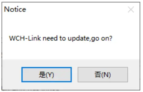
MounRiver Studio online update
If the firmware needs to be updated, MounRiver Studio will have a pop-up window to remind you when you click the download button, click Yes to start the update.

WCH-LinkUtility online update
If the firmware needs to be updated, WCH-LinkUtility will have a pop-up window to remind you when you click the download button, click Yes to start the update.
Notes:
- WCH-LinkE supports manual online update, the steps are as follows.
● Power up the Link after long press the IAP button until the blue LED blinks.
● MounRiver Studio/WCH-LinkUtility will have a pop-up window to remind you when you click the download button, click Yes to start the update. - If the Link firmware update is abnormal, please update the firmware by offline update.
WCH-LinkUtility offline update (2-wire approach to offline update)
- Connect WCH-LinkE with Link to be updated
WCH-LinkE
Link to be updated
3V3
3V3 GND GND
SWDIO
SWDIO SWCLK SWCLK
WCH-LinkE power on, select the Link chip model to be updated (WCH-LinkE main control chip isCH32V30x, WCH-DAPLink main control chip is CH32V20x)
- To be updated Link into IAP mode (long press the IAP button to power up the Link, that is, through the USB port connected to the computer to power up)
- Click Target->Clear All Code Flash-By Power off to erase all the user area of the chip.

- Click icon
 diaable chip read-protect

- Click icon
 , add Link offline updated firmware
 - Configuration options (Program + Verify + Reset and Run)

- Click icon
 to execute download
Notes:
- The Link to be updated is limited to WCH-LinkE and WCH-DAPLink.
- Two WCH-LinkE are required for this method.
- When Link enters IAP mode, the blue LED flashes.
WCHISPStudio serial port offline update
- Connect WCH-Link with USB to TTL module
WCH-Link
USB to TTL module
TX
RX
RX
TX
GND
GND
USB to TTL module power on, WCH-Link into BOOT mode (short connection J1 in Figure 1 will Link power on)
- Select chip model: CH549, download interface: serial port, device list: select the serial port number corresponding to the USB to TTL module

- Add Link offline updated firmware to target program file
- Download configuration

- Click the download button
- Click on the download and wait for the device to access the field, then plug the WCH-Link into the USB port, the ISP tool automatically began to download
Note: Serial port offline update is only supported by WCH-Link.
WCHISPStudio USB offline update
- To update the Link into BOOT mode (short connect J1 in Figure 1 or long press BOOT key and then power up the Link)
- WCHISPStudio tool will automatically pop up the adaptation window
- Add Link offline upgrade firmware to the target program file
- Download configuration

- Click the download button.
Notes:
- USB offline update is only supported by WCH-Link and WCH-DAPLink.
- WCH-LinkE-R0-1v3 and WCH-DAPLink-R0-2v0 are only available for firmware version v2.8 and above.
- WCH-LinkUtility tool can be exported through MounRiver Studio software.

- Link offline upgrade firmware is located in the MounRiver Studio installation path and WCH-LinkUtility installation path.

- WCH-DAPLink upgrade firmware
- WCH-LinkE upgrade firmware
- WCH-Link RISC-V mode upgrade firmware
- WCH-Link ARM mode upgrade firmware
- WCH-DAPLink offline upgrade firmware
- WCH-Link ARM mode offline upgrade firmware
- WCH-Link RISC-V mode offline upgrade firmware
- WCH-LinkE offline upgrade firmware
WCH-LinkE high-speed JTAG
Module overview
The WCH-LinkE-R0-1v3 provides a JTAG interface that supports 4-wire connections (TMS, TCK, TDI and TDO wires) for extending the JTAG interface for computers to operate CPUs, DSPs, FPGAs, CPLDs and other devices.

Module features
- As Host/Master host mode.
- l JTAG interface provides TMS wire, TCK wire, TDI wire and TDO wire.
- l Support high-speed USB data transfer.
- l Flexible operation of CPU, DSP, FPGA and CPLD devices through computer API cooperation.
Module switching
The WCH-LinkE-R0-1v3 can be upgraded to high-speed JTAG mode via the WCHLinkEJtagUpdTool tool, download the steps as follows.
- WCH-LinkE-R0-1v3 into IAP mode (long press the IAP button to power up the Link, i.e., connect to the computer through the USB port to power up), at this time the blue LED flashes.
- Open WCHLinkEJtagUpdTool tool, execute the download (WCH-LinkE high-speed JTAG upgrade firmware has been automatically added).
- Firmware update is complete, at this time the blue LED is always on.

Notes.
- WCHLinkEJtagUpdTool get URL: https://www.wch.cn/downloads/WCHLinkEJtagUpdToolZIP.html
- The firmware can be updated offline by WCH-LinkUtility tool, please refer to manual 6.3 WCH-LinkUtility Offline Update for details.
- WCH-LinkE high-speed JTAG offline update firmware is located in the WCHLinkEJtagUpdTool
installation path.

- WCH-LinkE high-speed JTAG upgrade firmware
- WCH-LinkE high-speed JTAG offline upgrade firmware
Download process
- In WCH-LinkE high-speed JTAG mode, the Bit program file is first downloaded to the FPGA via JTAG, and the Bit file will operate the SPI controller of the FPGA to convert the JTAG data to SPI data for writing to Flash, and this step is to write the BIN file to realize its program curing process.
- Here the FPGA is Xilinx xc7a35t. Write the CFG file and use “openocd -f” to call it. Name the CFG file as usb20jtag.cfg and save it to the location of the openocd.exe file.
# Specify WCH-LinkE high-speed JTAG debugger adapter driver ch347 ch347 vid_pid 0x1a86 0x55dd
# Set TCK clock frequency adapter speed 10000
# Specify TARGET, loading the JTAG-SPI driver in Open OCD
source [find cpld/xilinx-xc7.cfg] source [f nd cpld/jtagspi.cfg] # Set IR command of TARGET
set XC7_JSHUTDOWN 0x0d
set XC7_JPROGRAM 0x0b
set XC7_JSTART 0x0c
set XC7_BYPASS 0x3f
# Download process
Init
# First download the Bit file to TARGET
load 0 bscan_spi_xc7a35t.bit
reset halt
# Detect Flash information
flash probe 0
# Download Bin file to Flash flash write_image erase test. bin 0x0 bin
# Effective firmware operation irscan xc7.tap $XC7_JSHUTDOWN irscan xc7.tap $XC7_JPROGRAM runtest 60000 runtest 2000 irscan xc7.tap $XC7_BYPASS runtest 2000 exit . - Run the command: openocd.exe -f usb20jtag.cfg in Windows terminal and execute it as follows.

- The download is over and the device is running normally.
Notes.
- conversion role of the Bit file, with the help of Github open source project:
https://github.com/quartiq/bscanspibitstreams - openocd.exe file location: MounRiver\MounRiver_Studio\toolchain\OpenOCD\bin
Typical problem statement
|
Error Alert |
Solution |
Use Keil software to download |
|
Use Keil software to download |
|
Use MounRiver Studio software to download |
Note:
|
Use the WCH-LinkUtility tool to download |
Erase all user areas of the chip |
| Update firmware using WCHLinkEJtagUpdTool tool After updating the firmware according to manual 7.3 Mode Switching Download Procedure, the blue LED on the WCH-LinkE-R0-1v3 does not light up and the Device Manager cannot recognize the device. |
|


Notes:
- The debugging function is not supported when the user program turns on the sleep function.
- If you exit abnormally when using the debug function, it is recommended to re-plug the Link.
- When using the download and debug functions of CH32F103/CH32F203/CH32V103/CH32V203/ CH32V307, BOOT0 is grounded.
- When using the debug function of CH569, the user code must be smaller than the configured ROM space, as shown in Table 2-2 of CH569 manual.
- When using the debug function of CH32 series chip, please make sure the chip is in the read protection off state.
Driver installation
WCH-Link driver
If the driver installation fails, please open the LinkDrv folder under the installation path of MounRiver Studio or the Drv Link folder under the installation path of WCH-LinkUtility and install it manually. SETUP.EXE under the WCHLink folder.
|
Device manager |
Drive path |
 |
 |
WCH-LinkE high-speed JTAG driver
WCH-LinkE-R0-1v3 is upgraded to high-speed JTAG mode, you need to manually install the WCH-LinkE high-speed JTAG driver to use it properly. Please open the Drv folder under the installation path of WCHLinkEJtagUpdTool and install CH341PAR.EXE manually.
|
Device manager |
Drive pat |
 |
 |
CDC driver
CDC device installation problems under WIN7.
- If the serial port driver is successfully installed, the following steps are not required.
- Confirm that the usbser.sys file is present in path B. If it is missing, copy it from path A to path B.
- Reinstall the CDC driver. (See the above table for the driver path, please install the CDC driver in the corresponding mode)

Note: If the above steps do not solve the problem, please refer to the link below

Reference: http://www.wch.cn/downloads/InstallNoteOn64BitWIN7ZHPDF.html
Documents / Resources
 |
WCH WCH-Link Emulation Debugger Module [pdf] User Manual WCH-Link Emulation Debugger Module, WCH-Link, Emulation Debugger Module, Debugger Module |
![ELD LINK ERS-featured]](https://manuals.plus/wp-content/uploads/2021/04/ELD-LINK-ERS-featured-150x150.png)


