Truflo TIM Series Multi Functional Paddle Wheel Flow Meter

Specifications
- Operating Voltage
- Current Consumption
- Control Output
- Transmitter Communication
- Flow Rate GPM | LPM
- Fluid Accuracy
- Response Frequency
- Max Flow Rate
- Min Flow Rate
- Materials of Construction
- O-ring material
- Operating Temperature
- Protection Rating
- Approval *Optional
Product Information
The Multi-Function Paddle Wheel Flow Meter is designed to provide accurate and reliable flow measurements. It features a Zirconium Ceramic Rotor and Bushings for exceptional wear resistance and durability.
Safety Information
Before installation, ensure to de-pressurize and vent the system. Always confirm chemical compatibility and do not exceed maximum temperature or pressure specifications. Wear appropriate PPE during installation and service.
Installation Instructions
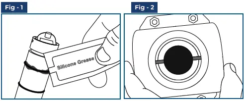
- Lubricate O-rings with a compatible viscous lubricant before installation.
- Carefully lower the sensor into the fitting using an alternating motion. Do not force.
- Ensure tab and notch are parallel to flow direction.
- Hand tighten the sensor cap without using any tools to avoid damage to threads.
Product Usage
Properly position the flow meter by following the alignment tab and fitting notch. Ensure the sensor is securely in place and parallel to the flow direction for accurate measurements.
FAQ
- Q: What should I do if I encounter a pressurized system warning?
- A: Take caution to vent the system prior to installation or removal to avoid equipment damage or injury.
- Q: Can I use tools during installation of the flow meter?
- A: Avoid using tools as it may cause irreparable damage to the product and void the warranty.
Truflo® — TIM Series
Multi-Function Paddle Wheel Flow Meter
Quick Start Manual
Read the user’s manual carefully before starting to use the unit. Producer reserves the right to implement changes without prior notice.
Safety Information
- De-pressurize and vent system prior to installation or removal
- Confirm chemical compatibility before use
- DO NOT exceed maximum temperature or pressure specifications
- ALWAYS wear safety goggles or face-shield during installation and/or service
- DO NOT alter product construction
Warning | Caution | Danger
Indicates a potential hazard. Failure to follow all warnings may lead to equipment damage, injury, or death.
Note | Technical Notes
Highlights additional information or detailed procedure.
Hand Tighten Only
Over tightening may permanently damage product threads and lead to failure of the retaining nut.
![]() Do Not Use Tools
Do Not Use Tools
Use of tool(s) may damage produced beyond repair and potentially void product warranty.
![]() Personal Protective Equipment (PPE)
Personal Protective Equipment (PPE)
Always utilize the most appropriate PPE during installation and service of Truflo products.
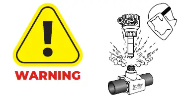
![]() Pressurized System Warning
Pressurized System Warning
Sensor may be under pressure. Take caution to vent system prior to installation or removal. Failure to do so may result in equipment damage and/or serious injury.
General Information
| General | Description |
| Operating Voltage | 10 – 30VDC |
| Current Consumption | 60mA max. |
| Control Output | NPN | 150mA max. |
| Transmitter | 4-20mA |
| Communication | RS485* |
| Flow Rate GPM | LPM | 0.0 – 999.9 |
| Fluid | H2O | Liquid Chemical Media |
| Accuracy | ± 0.5% of F.S. @25ºC |
| Response Frequency | 5K Hz |
| Max Flow Rate | 10m/s | 33ft/s |
| Min Flow Rate | 0.1m/s | 0.3ft/s |
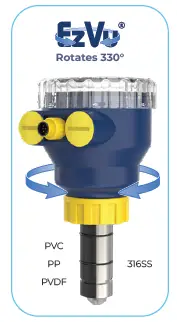
| Materials of Construction | Rotor: ETFE Tefzel® | Rotor Pin: Zirconium Ceramic | Rotor Bushings: Ceramic Sensor Body: PVC/PP/PVDF/316SS |
| O-ring material | FPM | EPDM Optional | FFKM Optional |
| Operating Temperature | PVC < 60ºC | PP < 80ºC | PF < 100ºC |
| Protection Rating | NEMA 4X | IP66 | General Purpose |
| Approval | CE |RoHS |
Industry’s Most Accurate & Reliable Paddle Wheel Flow Meters
The TI Series insertion plastic paddle wheel flow meter has been engineered to provide long-term accurate flow measurement in tough industrial applications.
The paddle wheel assembly consists of a engineered Tefzel® paddle and micro-polished zirconium ceramic rotor pin and bushings.
High performance Tefzel® and Zirconium materials have been selected due to their excellent chemical and wear resistant properties.
- ½” – 24” Line Sizes
- Flow Rate | Total
- Pulse | 4 – 20mA | Voltage Outputs
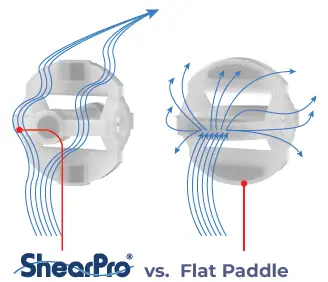
New ShearPro® Design
- Contoured Flow Profile
- Reduced Turbulence = Increased Longevity
- 78% Less Drag than Old Flat Paddle Design* *Ref: NASA “Shape Effects on Drag”

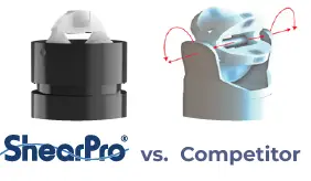
360º Shielded Rotor Design
- Eliminates Finger Spread
- No Lost Paddles
Installation
Very Important
- Lubricate O-rings with a viscous lubricant, compatible with the materials of construction.
- Using an alternating | twisting motion, carefully lower the sensor into the fitting. | Do Not Force | Fig 5
- Ensure tab | notch are parallel to flow direction | Fig-2
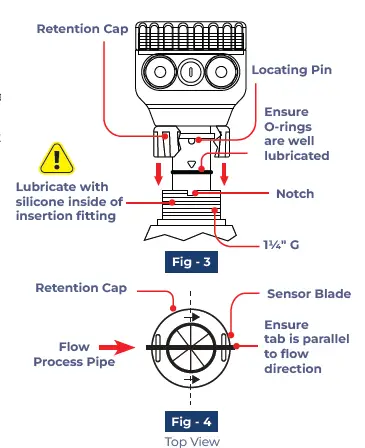
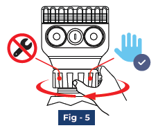
Hand tighten the sensor cap. DO NOT use any tools on the sensor cap or the cap threads or fitting threads may be damaged. | Fig-5
Correct Sensor Position
Correct Sensor Position Setup
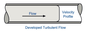
TI Series flow meters measure liquid media only. There should be no air bubbles and the pipe must always remain full. To ensure accurate flow measurement, the placement of the flow meters needs to adhere to specific parameters. This requires a straight run pipe with a minimum number of pipe diameters distance upstream and downstream of the flow sensor.


Terminal Connections
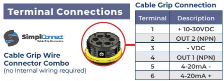
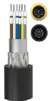
M12 Connection (no Internal wiring required)
| Terminal | Description | Color |
| 1 | + 10-30 VDC | Brown |
| 2 | Totalizer Pulse Output NPN | White |
| 3 | – VDC | Blue |
| 4 | Flow Rate Pulse Output NPN | Black |
| 5 | 4-20mA + | Yellow |
| 6 | 4-20mA – | Grey |
Fittings and K-Factor

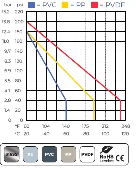
Pressure vs. Temperature
Note: During system design the specifications of all components must be considered. | Non-Shock
Min/Max Flow Rates
| Pipe Size (O.D.) | LPM | GPM | LPM | GPM |
| 0.3m/s min. | 10m/s max | |
| ½” | DN15 | 3.5 | 1.0 | 120.0 | 32.0 |
| ¾” | DN20 | 5.0 | 1.5 | 170.0 | 45.0 |
| 1″ | DN25 | 9.0 | 2.5 | 300.0 | 79.0 |
| 1 ½” | DN40 | 25.0 | 6.5 | 850.0 | 225.0 |
| 2″ | DN50 | 40.0 | 10.5 | 1350.0 | 357.0 |
| 2 ½” | DN60 | 60.0 | 16.0 | 1850.0 | 357.0 |
| 3″ | DN80 | 90.0 | 24.0 | 2800.0 | 739.0 |
| 4″ | DN100 | 125.0 | 33.0 | 4350.0 | 1149.0 |
| 6″ | DN150 | 230.0 | 60.0 | 7590.0 | 1997.0 |
| 8″ | DN200 | 315.0 | 82.0 | 10395.0 | 2735.0 |
![]()
Programming

Programming Frequency Pulse Relay Output

Programming Relay Output


Relay Option Outputs
| ALt No. | Description |
| ALt = 0 | CV > SV —▶ ON: CV < SV – Hys —▶ OFF ‘Normally Closed Relay’ |
| ALt = 1 | CV < SV —▶ ON: CV > SV + Hys —▶ OFF ‘Normally Open Relay’ |
| ALt = 2 | SV + Hys > CV > SV – Hys —▶ ON: CV > SV + Hys or CV < SV – HyS —▶ OFF |
| ALt = 3 | SV + Hys > CV > SV – Hys —▶ OFF: CV > SV + Hys or CV < SV – HyS —▶ ON |
| Hys = Hysteresis — Acts like a buffer ± around pulse output (measured in GPM) | |
| CV: Current Value = Flow Rate | SV = Selected or Programmed Value | |
Rotor Pin | Paddle Replacement


Warranty, Returns and Limitations
Warranty
Icon Process Controls Ltd warrants to the original purchaser of its products that such products will be free from defects in material and workmanship under normal use and service in accordance with instructions furnished by Icon Process Controls Ltd for a period of one year from the date of sale of such products. Icon Process Controls Ltd obligation under this warranty is solely and exclusively limited to the repair or replacement, at Icon Process Controls Ltd option, of the products or components, which Icon Process Controls Ltd examination determines to its satisfaction to be defective in material or workmanship within the warranty period. Icon Process Controls Ltd must be notified pursuant to the instructions below of any claim under this warranty within thirty (30) days of any claimed lack of conformity of the product. Any product repaired under this warranty will be warranted only for the remainder of the original warranty period. Any product provided as a replacement under this warranty will be warranted for the one year from the date of replacement.
Returns
Products cannot be returned to Icon Process Controls Ltd without prior authorization. To return a product that is thought to be defective, go to www.iconprocon.com, and submit a customer return (MRA) request form and follow the instructions therein. All warranty and non-warranty product returns to Icon Process Controls Ltd must be shipped prepaid and insured. Icon Process Controls Ltd will not be responsible for any products lost or damaged in shipment.
Limitations
This warranty does not apply to products which: 1) are beyond the warranty period or are products for which the original purchaser does not follow the warranty procedures outlined above; 2) have been subjected to electrical, mechanical or chemical damage due to improper, accidental or negligent use; 3) have been modified or altered; 4) anyone other than service personnel authorized by Icon Process Controls Ltd have attempted to repair; 5) have been involved in accidents or natural disasters; or
6) are damaged during return shipment to Icon Process Controls Ltd reserves the right to unilaterally waive this warranty and dispose of any product returned to Icon Process Controls Ltd where: 1) there is evidence of a potentially hazardous material present with the product; or 2) the product has remained unclaimed at Icon Process Controls Ltd for more than 30 days after Icon Process Controls Ltd has dutifully requested disposition. This warranty contains the sole express warranty made by Icon Process Controls Ltd in connection with its products. ALL IMPLIED WARRANTIES, INCLUDING WITHOUT LIMITATION, THE WARRANTIES OF MERCHANTABILITY AND FITNESS FOR
A PARTICULAR PURPOSE, ARE EXPRESSLY DISCLAIMED. The remedies of repair or replacement as stated above are the exclusive remedies for the breach of this warranty. IN NO EVENT SHALL Icon Process Controls Ltd BE LIABLE FOR ANY INCIDENTAL OR CONSEQUENTIAL DAMAGES OF ANY KIND I NCLUDING PERSONAL OR REAL PROPERTY OR FOR INJURY TO ANY PERSON. THIS WARRANTY CONSTITUTES THE FINAL, COMPLETE AND EXCLUSIVE STATEMENT OF WARRANTY TERMS AND NO PERSON IS AUTHORIZED TO MAKE ANY OTHER WARRANTIES OR REPRESENTATIONS ON BEHALF OF Icon Process Controls Ltd. This warranty will be interpreted pursuant to the laws of the province of Ontario, Canada.
If any portion of this warranty is held to be invalid or unenforceable for any reason, such finding will not invalidate any other provision of this warranty.
For additional product documentation and technical support visit: www.iconprocon.com | e-mail: sales@iconprocon.com or support@iconprocon.com | Ph: 905.469.9283
 Phone: 905.469.9283
- Sales: sales@iconprocon.com
- Support: support@iconprocon.com
Documents / Resources
 |
Truflo TIM Series Multi Functional Paddle Wheel Flow Meter [pdf] User Manual TIM Series Multi Functional Paddle Wheel Flow Meter, TIM Series, TIM Series Paddle Wheel Flow Meter, Multi Functional Paddle Wheel Flow Meter, Paddle Wheel Flow Meter, Paddle Wheel Meter, Flow Meter, Meter |


