TRANE CXAU-MODBUS Cxau Centralized Controller Communication

Product Information
Specifications
- Product: CXAU Centralized Controller MODBUS Communication
- Manual Version: May 2023
- Model Number: CXAU-MODBUS-EN
Installation Guide
Precautions
- All wiring needs to comply with local laws and regulations.
- Power cable size recommendation: 0.75mm2
- Communication line requirements:
- RS485 wiring must use twisted pair shielded wire RVSP.
- Wire diameter: AWG #16 ~ 18 (American wire standard) or 0.75mm2 (Chinese wire standard).
- Twisted pair with the shield.
- The twisting distance should not exceed 5cm.
- When the power cable is routed parallel to the communication line, enough distance must be maintained.
- RS485 communication line must use twisted pair shielded wire RVSP, and other types of cables shall not be used instead.
- RS485 bus must adopt a hand-in-hand structure and must not use a star connection.
- RS485 communication line should be as far away as possible from high-voltage wire, and cannot be routed with the power line, letalone bundled together.
- Ethernet communication line requirements: Ethernet communication lines must use shielded CAT 5 network cables.
Operation
Centralized Controller Address Settings
Set in User >> Other Settings
- For RS485 use, the default address for the slave unit is 1,changeable.
- Ethernet interface:
- IP Address: 192.168.0.200
- Subnet Mask: 255.255.255.0
- Default Gateway: 192.168.0.1
- Port ID: 502 (not changeable)
Communication Port
- Physical interface: COM4
- RS485 Communication protocol: ModbusRTU
- Baud rate setting: 9600,N,8,1
Ethernet Communication Interface
- Physical interface: RJ45
- Communication protocol: Modbus TCPRTU
Communication Protocol
Modbus Directive Definitions
- The communication mode uses Modbus RTU mode. The data format is defined as follows:
- Slave address
- Module address
- Data is binary data.
- Request code
- Function code
- Data
- CRC16 Check code
- RTU mode is formatted as per byte (10 bits):
- 1 Start bit
- 8 Data bits (LSB first)
- 1 Stop bit
- Broadcast frames:
- Address 0 is used by the host to send broadcast frames.
- The Modbus module can receive broadcast frames and execute the
corresponding requests but does not return reply frames to the host. - Broadcast requests are typically used to write commands.
- There can be two ways to talk about master-slave dialogue:
- The host sends a request to a slave and waits for a response from the slave.
- The host sends a broadcast to all slaves and does not wait for a response from the slaves.
- Instructions to read the coil registers (0x01) sent by the host unit:
- Slave unit address
- Function code
- The first address of the register
- The number of coils read
- CRC16-Lo
- CRC16-Hi
- Response from the module:
- Slave unit address
- Function code
- The length of the data read
- 1st byte to nth byte
- CRC16-Lo
- CRC16-Hi
FAQ (Frequently Asked Questions)
- Q: What is the recommended power cable size for installation?
- A: The recommended power cable size is 0.75mm2.
- Q: What type of cable should be used for RS485 communication line?
- A: RS485 communication line must use twisted pair shielded wireRVSP.
- Q: Can I use other types of cables instead of twisted pairshielded wire RVSP for RS485 communication line?
- A: No, other types of cables should not be used for RS485 communication line.
- Q: Can I route the power cable parallel to the communication line?
- A: If routing the power cable parallel to the communicationline, ensure enough distance is maintained.
- Q: Can I use a star connection for the RS485 bus?
- A: No, the RS485 bus must adopt a hand-in-hand structure and must not use a star connection.
- Q: What type of cable should be used for Ethernet communication lines?
- A: Ethernet communication lines must use shielded CAT 5 network cables.
Installation Operation and Maintenance Manual
CXAU Centralized Controller MODBUS Communication
Feature
- The device is used for centralized control of Trane air conditioning modular CXAU products, and up to 16 CXAU units can be connected to one device;
- Mounting: 4 x 7mm mounting holes.
- Overall dimensions (W x H x D): 250 x 220 x 90 (mm).
- Working power supply: 220/230VAC.
- Working environment: temperature -10~60°C, humidity < 90% RH.
- Storage environment: temperature -20~70°C, humidity < 90% RH.
Installation Guide
Installation
Precautions
- The equipment should be installed indoors, far away from heat sources, such as vapors or flammable gases, and far away from converter substations.
- Do not install the device in a location exposed to direct sunlight.
- Do not install the device in a location with strong wind or heavy dust.
- Do not install the device in a location prone to rain or high moisture.
- Do not install the device in a location where acids, alkaline substances, or corrosive gases (such as sulfur dioxide, hydrogen sulfide, etc.) are present.
- Do not install the device in a location where combustible gases or volatile combustibles may leak into.
- Do not install the device in a location where small animal nests are likely to occur.
- Do not install the device in a location easily accessible to movable people.
Wiring Instructions
- All wiring needs to comply with local laws and regulations.
- Power cable size recommendation≥ 0.75mm2
- Communication line requirements: RS485 wiring must use twisted pair shielded wire RVSP. Wire diameter AWG #16 ~ 18 (American wire standard), or ≥ 0.75mm2 (Chinese wire standard). Twisted pair with the shield. The twisting distance is not more than 5cm.
- When the power cable is routed parallel to the communication line, enough distance must be maintained.
- RS485 communication line must use twisted pair shielded wire RVSP, and other types of cables shall not be used instead.
- RS485 bus must adopt a hand-in-hand structure and must not use a star connection.
- RS485 communication line should be as far away as possible from high-voltage wire, and can not be routed with the power line, let alone bundled together.
- Ethernet communication line requirements: Ethernet communication lines must use shielded CAT 5 network cables.
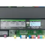
Centralized Controller Diagram:

Operation
Centralized Controller Address Settings
Set in User>>Other Settings
For RS485 use, default address for slave unit is 1, changeable. Ethernet interface:
- IP Address: 192.168.0.200 changeable
- Subnet Mask: 255.255.255. 0 changeable
- Default Gateway: 192.168.0.1 changeable
- Port ID: 502 not changeable
Communication Port
- Physical interface: COM4 RS485
- Communication protocol: Modbus/RTU
- Baud rate setting: 9600,N,8,1
- Ethernet communication interface
- Physical interface: RJ45
- Communication protocol:Modbus TCP/RTU
Communication protocol
Modbus Directive definitions
- The communication mode uses Modbus RTU mode. The data format is defined as follows:
| Slave address | Request code | Data | CRC16 |
| Module address | Function code | data | Check code |
Data is binary data.
- CRC16: Cyclic redundancy check.
RTU mode is formatted as per byte (10 bits):
- Start bit、8 Data bits, The lowest significant bit is sent first(LSB first)、Stop bit Broadcast frames:
Address 0 is used by the host to send broadcast frames,The Modbus module can receive broadcast frames and execute the corresponding requests, but does not return reply frames to the host. Broadcast requests are typically used to write commands.
There can be two ways to talk about master-slave dialogue: - The host sends a request to a slave and waits for a response from the slave.
- The host sends a broadcast to all slaves and does not wait for a response from the slaves.
Instructions to read the coil registers (0x01)
- Sent by the host unit:
Slave unit address 1 byte 0x01~0x10 Function code 1 byte 0x01 The first address of the register 2 bytes 0x0000 to 0xFFFF The number of coils read 2 bytes 1 to 2000 CRC16-Lo 1 byte CRC16-Hi 1 byte - Respond from the module:
| Slave unit address | 1 byte | 0x01~0x10 |
| Function code | 1 byte | 0x01 |
| The length of the data read | 2 bytes | 0x0000 to 0xFFFF |
| 1st byte | 1 byte | |
| ……… | ……… | ……… |
| The nth byte | 1 byte | |
| CRC16-Lo | 1 byte | |
| CRC16-Hi | 1 byte |
Example: Read the air conditioning system power on and off instructions。
| Send | Response | ||
| name | (Hex) | name | (Hex) |
| Device address | 01 | Device address | 01 |
| Function code | 01 | Function code | 01 |
| Start address Hi | 00 | Number of bytes | 01 |
| Start address Lo | 0A | Output status 0 – 7 | shutdown[00],startup[01]; |
| The number of output states Hi | 00 | CRC16 Lo | 51 |
| The number of output states Lo | 01 | CRC16 Hi | 88 |
| CRC16 Lo | DD | ||
| CRC16 Hi | C8 | ||
Instructions to read discrete registers(0x02)
- Sent by the host unit:
Slave unit address 1 byte 0x01~0x10 Function code 1 byte 0x02 The first address on the register 2 bytes 0x0000 to 0xFFFF The number of coils read 2 bytes 1 to 2000 CRC16-Lo 1 byte CRC16-Hi 1 byte - Respond from the module:
| Slave unit address | 1 byte | 0x01~0x10 |
| Function code | 1 byte | 0x02 |
| The length of the data read | 2 bytes | 0x0000 to 0xFFFF |
| 1st byte | 1 byte | |
| ……… | ……… | ……… |
| The nth byte | 1 byte | |
| CRC16-Lo | 1 byte | |
| CRC16-Hi | 1 byte |
Example:Read the power on and off status of the air conditioning system.
| Send | Response | ||
| 名称 | (Hex) | name | (Hex) |
| Device address | 01 | Device address | 01 |
| Function code | 02 | Function code | 02 |
| Start address Hi | 00 | Number of bytes | 01 |
| Start addressLo | 0B | Output status 0 – 7 | Shutdown[00],startup[01]; |
| The number of output states Hi | 00 | CRC16 Lo | A1 |
| The number of output states Lo | 01 | CRC16 Hi | 88 |
| CRC16 Lo | C8 | ||
| CRC16 Hi | 08 | ||
Read save register instructions(0x03)
- Sent by the host unit:
Slave unit address 1 byte 0x01~0x10 Function code 1 byte 0x03 The first address of the register 2 bytes 0x0000 to 0xFFFF Number of register read 2 bytes 1 to 125 CRC16-Lo 1 byte CRC16-Hi 1 byte - Respond from the module:
| Slave unit address | 1 byte | 0x01~0x10 |
| Function code | 1 byte | 0x03 |
| The byte length of the read data | 2 bytes | |
| The first register value | 2bytes | |
| ……… | ……… | ……… |
| The nth register value | 2 bytes | |
| CRC16-Lo | 1 byte | |
| CRC16-Hi | 1 byte |
Example:Read the refrigeration entering temperature setpoint. Its register address is 10000,hexadecimal 0x2710,Its register value is 120(denote 12°C),Hexadecimal is 0x78.
| Send | Response | ||
| name | (Hex) | name | (Hex) |
| Device address | 01 | Device address | 01 |
| Function code | 03 | Function code | 03 |
| Start address Hi | 27 | Number of bytes | 02 |
| Start address Lo | 10 | Register value Hi | 00 |
| Number of registers Hi | 00 | Register value Lo | 78 |
| Number of registers Lo | 01 | CRC16 Lo | B8 |
| CRC16 Lo | 8F | CRC16 Hi | 66 |
| CRC16 Hi | 7B | ||
Read input register instructions(0x04)
- Sent by the host unit:
Slave unit address 1 byte 0x01~0x10 Function code 1 byte 0x04 First address of the register 2 bytes 0x0000 to 0xFFFF Register number read 2 bytes 1 to 125 CRC16-Lo 1 byte CRC16-Hi 1 byte - Feedback from model:
| Slave unit address | 1 byte | 0x01~0x10 |
| Function code | 1 byte | 0x04 |
| The byte length of the read data | 2 bytes | |
| The first register value | 2bytes | |
| ……… | ……… | ……… |
| The nth register value | 2 bytes | |
| CRC16-Lo | 1 byte | |
| CRC16-Hi | 1 byte |
Example:Read the ambient temperature, entering water temperature and leaving water temperature of Unit 2。Its starting register address is 80+20*2=120,The correspondinghexadecimal is 0x78,The register values are 152(denote 15.2°C)、304(denote30.4°C)、 335(denote33.5°C)respectively。
| Send | Response | ||
| name | (Hex) | name | (Hex) |
| Device address | 01 | Device address | 01 |
| Function code | 04 | Function code | 04 |
| Start address Hi | 00 | Number of bytes | 06 |
| Start address Lo | 78 | Register value Hi | 00 |
| Number of registers Hi | 00 | Register value Lo | 98 |
| Number of registers Lo | 03 | Register value Hi | 01 |
| CRC16 Lo | 30 | Register value Lo | 30 |
| CRC16 Hi | 12 | Register value Hi | 01 |
| Register value Lo | 4F | ||
| CRC16 Lo | 00 | ||
| CRC16 Hi | D8 | ||
Write a single coil register instruction(0x05)
- Sent by the host unit:
Slave unit address 1 byte 0x01~0x10 Function code 1 byte 0x05 The address of the register 2 bytes 0x0000 to 0xFFFF The value of the register 2 bytes close[0x0000] or open[ 0xFF00] CRC16-Lo 1 byte CRC16-Hi 1 byte - Respond from the module:
| Slave unit address | 1 byte | 0x01~0x10 |
| Function code | 1 byte | 0x05 |
| The address of the register | 2 bytes | 0x0000 to 0xFFFF |
| The value of the register | 2 bytes | close[0x0000] or open[ 0xFF00] |
| CRC16-Lo | 1 byte | |
| CRC16-Hi | 1 byte |
Example:Write the air conditioning system power on and off instructions, the register address is10.
| Send | Response | ||
| name | (Hex) | name | (Hex) |
| Device address | 01 | Device address | 01 |
| Function code | 05 | Function code | 05 |
| The address of the register Hi | 00 | The address of the register Hi | 00 |
| The address of the register Lo | 0A | The address of the register Lo | 0A |
| The value of the register Hi | FF | The value of the register Hi | FF |
| The value of the register Lo | 00 | The value of the register Lo | 00 |
| CRC16 Lo | AC | CRC16 Lo | AC |
| CRC16 Hi | 38 | CRC16 Hi | 38 |
Write a single hold-register instruction(0x06)
- Sent by the host unit:
Slave unit address 1 byte 0x01~0x10 Function code 1 byte 0x06 The address of the register 2 bytes 0x0000 to 0xFFFF The value of the register 2 bytes 0x0000 to 0xFFFF CRC16-Lo 1 byte CRC16-Hi 1 byte - Respond from the module:
| Slave unit address | 1 byte | 0x01~0x10 |
| Function code | 1 byte | 0x06 |
| The address of the register | 2 bytes | 0x0000 to 0xFFFF |
| The value of the register | 2 bytes | 0x0000 to 0xFFFF |
| CRC16-Lo | 1 byte | |
| CRC16-Hi | 1 byte |
Example:Write the entering water temperature setpoint. Its register address is 10000,hexadecimal 0x2710,Its register value is 100(denote10°C),hexadecimal is 0x78。
| Send | Response | ||
| name | (Hex) | name | (Hex) |
| Device address | 01 | Device address | 01 |
| Function code | 06 | Function code | 06 |
| The address of the register Hi | 27 | The address of the register Hi | 27 |
| The address of the register Lo | 10 | The address of the register Lo | 10 |
| The value of the register Hi | 00 | The value of the register Hi | 00 |
| The value of the register Lo | 64 | The value of the register Lo | 64 |
| CRC16 Lo | 4F | CRC16 Lo | 4F |
| CRC16 Hi | 50 | CRC16 Hi | 50 |
Error response
When the slave cannot execute the host’s request, this frame is responded to the host.
| Module address | Response code | Error code | CRC16 | |
| 0x01~0x0F | 83 or 86 | 1~6 | Lo | Hi |
| 1 byte | 1 byte | 1 byte | 2 bytes | |
Response Code = Function Code+0x80
Error code:
- 01 = Illegal features
- 02 = Illegal data address
- 03 = Illegal data values
- 06 = The slave is busy
remark:
- Hi represents the data high byte,Lo represents a data low byte。
- The module address changes according to the address set by dialing code SW3.
Modbus Data register address table
The air conditioning system on/off status(Function code:0x01[read],0x05[write])
| Register address | Data type |
Data name |
Range |
Default value |
Read(R) Write(W) |
Description |
| 10 | binary | On/off status | (0,1) | 0 | RW | 0:off;1:on |
Air conditioning system power on and off status (function code: 0x02 [read])
| Register address | Data type |
Data name |
Range |
Default value |
Read(R) Write(W) |
Description |
| 11 | binary | On/off status | (0,1) | 0 | R | 0:off;1:on |
Air conditioning system setting table (function code: 0x03 [read], 0x06 [write])
| Register address | Data type |
Data name |
Range |
Default value | Read(R) Write(W) |
Description |
|
10000 |
word |
entering water temperature setpoint in
cooling mode,℃ |
(100,250) |
120 |
RW |
Variable value*0.1°C
is the temperature value |
|
10001 |
word |
leaving water temperature setpoint in
cooling mode,℃ |
(50,200) |
70 |
RW |
Variable value*0.1°C is the temperature value |
|
10002 |
word |
entering water temperature setpoint in
heating mode,℃ |
(250,500) |
400 |
RW |
Variable value*0.1°C is the temperature value |
|
10003 |
word |
leaving water temperature setpoint in
heating mode,℃ |
(300,550) |
450 |
RW |
Variable value*0.1°C
is the temperature value |
|
10004 |
word |
Hot water temperature setpoint,℃ |
(30,120) |
80 |
RW |
Variable value*0.1°C
is the temperature value |
|
10020 |
Word |
Current operation mode (cooling/heating) | Current operation mode (cooling/heating) |
0 |
RW |
cooling and heating mode |
Air conditioning system datasheet (function code:0x04[read])
| Register address | Data type |
Data name |
Range |
Default value | Read(R) Write(W) |
Description |
|
10 |
word |
Current operation mode(cooling/heating) |
0:Cooling; 1:Heating; |
R |
||
| 13 | word | Number of units | Number of units | R |
| No. N machine data sheet (11 in total) (function code: 0x04 [read]) | ||||||
| Register address | Data type |
Data name |
Range |
Default |
Read(R) Write(W) |
Description |
|
80+20*n |
word |
Ambient temperature (TH1) |
(-32768,32767) |
R |
Variable value*0.1°C is
the temperature value |
|
|
80+20*n+1 |
word |
entering water temperature(TH2) |
(-32768,32767) |
R |
Variable value*0.1°C is
the temperature value |
|
|
80+20*n+2 |
word |
Leaving water temperature(TH3) |
(-32768,32767) |
R |
Variable value*0.1°C is the temperature
value |
|
|
80+20*n+3 |
word |
Total leaving temperature(reserved)
(TH4) |
(-32768,32767) |
R |
Variable value*0.1°C is the temperature
value |
|
|
80+20*n+4 |
word |
Unit operating status |
0:Undefined; 1:Not activated; 2:Stopped; 3:Starting;
4:run; 5:Stopping |
R |
||
|
80+20*n+5 |
word |
System 1 operating status |
0:Undefined; 1:Not activated; 2:Stopped; 3:Starting;
4:run; 5:Stopping |
R |
||
|
80+20*n+6 |
word |
System 2 operating status |
0:Undefined; 1:Not activated; 2:Stopped; 3:Starting; 4:run;
5:Stopping |
R |
||
|
80+20*n+7 |
word |
Compressor 1A operating state |
0:Undefined; 1:Not activated; 2:Stopped; 3:Starting;
4:run; 5:Stopping |
R |
||
|
80+20*n+8 |
word |
Compressor 1B operating state |
0:Undefined; 1:Not activated; 2:Stopped; 3:Starting;
4:run; 5:Stopping |
R |
||
|
80+20*n+9 |
word |
Compressor 2A operating state |
0:Undefined; 1:Not activated; 2:Stopped; 3:Starting; 4:run;
5: Stopping |
R |
||
|
80+20*n+1 0 |
word |
Compressor 2B operating state |
0:Undefined; 1:Not activated; 2:Stopped; 3:Starting; 4:run;
5: Stopping |
R |
| Air conditioning system alarm table 10051—10084(Total 34)(Function code:0x02[read]) | ||||||
| Register address |
Data type |
Data name |
Range |
Default |
Read(R) Write(W) |
Description |
| 50 | binary | Fault flag | (0,1) | – | R | 0:No alarm;1: Alarm |
| 51 | binary | Unit 1 communication alarm | (0,1) | – | R | 0:No alarm;1: Alarm |
| 52 | binary | Unit 2 communication alarm | (0,1) | – | R | 0:No alarm;1: Alarm |
| 53 | binary | Unit 3 communication alarm | (0,1) | – | R | 0:No alarm;1: Alarm |
| 54 | binary | Unit 4 communication alarm | (0,1) | – | R | 0:No alarm;1: Alarm |
| 55 | binary | Unit 5 communication alarm | (0,1) | – | R | 0:No alarm;1: Alarm |
| 56 | binary | Unit 6 communication alarm | (0,1) | – | R | 0:No alarm;1: Alarm |
| 57 | binary | Unit 7 communication alarm | (0,1) | – | R | 0:No alarm;1: Alarm |
| 58 | binary | Unit 8 communication alarm | (0,1) | – | R | 0:No alarm;1: Alarm |
| 59 | binary | Unit 9 communication alarm | (0,1) | – | R | 0:No alarm;1: Alarm |
| 60 | binary | Unit 10 communication alarm | (0,1) | – | R | 0:No alarm;1: Alarm |
| 61 | binary | Unit 11 communication alarm | (0,1) | – | R | 0:No alarm;1: Alarm |
| 62 | binary | Unit 12 communication alarm | (0,1) | – | R | 0:No alarm;1: Alarm |
| 63 | binary | Unit 13 communication alarm | (0,1) | – | R | 0:No alarm;1: Alarm |
| 64 | binary | Unit 14 communication alarm | (0,1) | – | R | 0:No alarm;1: Alarm |
| 65 | binary | Unit 15 communication alarm | (0,1) | – | R | 0:No alarm;1: Alarm |
| 66 | binary | Unit 16 communication alarm | (0,1) | – | R | 0:No alarm;1: Alarm |
| 67 | binary | Reserved | (0,1) | – | R | |
| 68 | binary | The water pump on the air conditioning side is overloaded | (0,1) | – | R | 0:Not overload; 1:overload |
| 69 | binary | Hot water side pump overload
(reserved) |
(0,1) | – | R | 0:Not overload; 1:overload |
| 70 | binary | Electric heater in the air conditioning side is overloaded | (0,1) | – | R | 0:Not overload; 1:overload |
| 71 | binary | The entering water temperature sensor alarm | (0,1) | – | R | 0:No alarm;1: Alarm |
| 72 | binary | The leaving water temperature sensor alarm | (0,1) | – | R | 0:No alarm;1: Alarm |
| 73 | binary | The total leaving temperature sensor alarm | (0,1) | – | R | 0:No alarm;1: Alarm |
| 74 | binary | Centralized controller communication alarm | (0,1) | – | R | 0:No alarm;1: Alarm |
| 75 | binary | Reserved | (0,1) | – | R | |
| 76 | binary | Reserved | (0,1) | – | R | |
| 77 | binary | Reserved | (0,1) | – | R | |
| 78 | binary | Reserved | (0,1) | – | R | |
| 79 | binary | Reserved | (0,1) | – | R | |
| 80 | binary | Reserved | (0,1) | – | R | |
| 81 | binary | Reserved | (0,1) | – | R | |
| 82 | binary | Reserved | (0,1) | – | R | |
| 83 | binary | Reserved | (0,1) | – | R | |
| Unit N alarm table(total 59)(Function code:0x02[read]) | ||||||
| Register address |
Data type |
Data name |
Range |
Default |
Read(R) Write(W) |
Description |
| 100*n | binary | Low Water Flow | (0,1) | – | R | 0:no alarm;1: alarm |
| 100*n+1 | binary | Flow Switch Error | (0,1) | – | R | 0:no alarm;1: alarm |
| 100*n+2 | binary | Large Diff For EWT and LWT in Heating | (0,1) | – | R | 0:no alarm;1: alarm |
| 100*n+3 | binary | EWT and LWT Abnormal | (0,1) | – | R | 0:no alarm;1: alarm |
| 100*n+4 | binary | Anti-Freezing 1 | (0,1) | – | R | 0:no alarm;1: alarm |
| 100*n+5 | binary | Anti-Freezing 2 | (0,1) | – | R | 0:no alarm;1: alarm |
| 100*n+6 | binary | Outdoor Air Temp Out Of Range | (0,1) | – | R | 0:no alarm;1: alarm |
| 100*n+7 | binary | Entering Water Temp Sensor | (0,1) | – | R | 0:no alarm;1: alarm |
| 100*n+8 | binary | Leaving Water Temp Sensor | (0,1) | – | R | 0:no alarm;1: alarm |
| 100*n+9 | binary | Outdoor Air Temp Sensor | (0,1) | – | R | 0:no alarm;1: alarm |
| 100*n+10 | binary | Configuration Error | (0,1) | – | R | 0:no alarm;1: alarm |
| 100*n+11 | binary | EEPROM Error | (0,1) | – | R | 0:no alarm;1: alarm |
| 100*n+12 | binary | High Inlet Water Temp Limit | (0,1) | – | R | 0:no alarm;1: alarm |
| 100*n+13 | binary | High Outlet Water Temp Limit | (0,1) | – | R | 0:no alarm;1: alarm |
| 100*n+14 | binary | Sub Board Comm Loss | (0,1) | – | R | 0:no alarm;1: alarm |
| 100*n+15 | binary | reserved 1 | (0,1) | – | R | 0:no alarm;1: alarm |
| 100*n+16 | binary | Compressor Overload Ckt1 | (0,1) | – | R | 0:no alarm;1: alarm |
| 100*n+17 | binary | Fan Overload Ckt1 | (0,1) | – | R | 0:no alarm;1: alarm |
| 100*n+18 | binary | Current Abnormal Comp1A | (0,1) | – | R | 0:no alarm;1: alarm |
| 100*n+19 | binary | Current Abnormal Comp1B | (0,1) | – | R | 0:no alarm;1: alarm |
| 100*n+20 | binary | High Pressure Protection Ckt1 | (0,1) | – | R | 0:no alarm;1: alarm |
| 100*n+21 | binary | Low Pressure Protection Ckt1 | (0,1) | – | R | 0:no alarm;1: alarm |
| 100*n+22 | binary | Discharge Temp Protection Ckt1 | (0,1) | – | R | 0:no alarm;1: alarm |
| 100*n+23 | binary | Low Superheat Ckt1 | (0,1) | – | R | 0:no alarm;1: alarm |
| 100*n+24 | binary | Discharge Pressure Sensor Ckt1 | (0,1) | – | R | 0:no alarm;1: alarm |
| 100*n+25 | binary | Suction Pressure Sensor Ckt1 | (0,1) | – | R | 0:no alarm;1: alarm |
| 100*n+26 | binary | Refrigerant Leakage Ckt1 | (0,1) | – | R | 0:no alarm;1: alarm |
| 100*n+27 | binary | Discharge Temp Sensor Ckt1 | (0,1) | – | R | 0:no alarm;1: alarm |
| 100*n+28 | binary | Coil Temp Sensor Ckt1 | (0,1) | – | R | 0:no alarm;1: alarm |
| 100*n+29 | binary | Suction Temp Sensor Ckt1 | (0,1) | – | R | 0:no alarm;1: alarm |
| 100*n+30 | binary | High Suction Temp Ckt1 | (0,1) | – | R | 0:no alarm;1: alarm |
| 100*n+31 | binary | Reserved 2 | (0,1) | – | R | 0:no alarm;1: alarm |
| 100*n+32 | binary | Compressor Overload Ckt2 | (0,1) | – | R | 0:no alarm;1: alarm |
| 100*n+33 | binary | Fan Overload Ckt2 | (0,1) | – | R | 0:no alarm;1: alarm |
| 100*n+34 | binary | Current Abnormal Comp2A | (0,1) | – | R | 0:no alarm;1: alarm |
| 100*n+35 | binary | Current Abnormal Comp2B | (0,1) | – | R | 0:no alarm;1: alarm |
| 100*n+36 | binary | High Pressure Protection Ckt2 | (0,1) | – | R | 0:no alarm;1: alarm |
| 100*n+37 | binary | Low Pressure Protection Ckt2 | (0,1) | – | R | 0:no alarm;1: alarm |
| 100*n+38 | binary | Discharge Temp Protection Ckt2 | (0,1) | – | R | 0:no alarm;1: alarm |
| 100*n+39 | binary | Low Superheat Ckt2 | (0,1) | – | R | 0:no alarm;1: alarm |
| 100*n+40 | binary | Discharge Pressure Sensor Ckt2 | (0,1) | – | R | 0:no alarm;1: alarm |
| 100*n+41 | binary | Suction Pressure Sensor Ckt2 | (0,1) | – | R | 0:no alarm;1: alarm |
| 100*n+42 | binary | Refrigerant Leakage Ckt2 | (0,1) | – | R | 0:no alarm;1: alarm |
| 100*n+43 | binary | Discharge Temp Sensor Ckt2 | (0,1) | – | R | 0:no alarm;1: alarm |
| 100*n+44 | binary | Coil Temp Sensor Ckt2 | (0,1) | – | R | 0:no alarm;1: alarm |
| 100*n+45 | binary | Suction Temp Sensor Ckt2 | (0,1) | – | R | 0:no alarm;1: alarm |
| 100*n+46 | binary | High Suction Temp Ckt2 | (0,1) | – | R | 0:no alarm;1: alarm |
| 100*n+47 | binary | Reserved 3 | (0,1) | – | R | 0:no alarm;1: alarm |
| 100*n+48 | binary | High Bus Voltage Ckt1-Fan1 | (0,1) | – | R | 0:no alarm;1: alarm |
| 100*n+49 | binary | Low Bus Voltage Ckt1-Fan1 | (0,1) | – | R | 0:no alarm;1: alarm |
| 100*n+50 | binary | High IPM Temp Ckt1-Fan1 | (0,1) | – | R | 0:no alarm;1: alarm |
| 100*n+51 | binary | High Output Power Ckt1-Fan1 | (0,1) | – | R | 0:no alarm;1: alarm |
| 100*n+52 | binary | Other Protection Ckt1-Fan1 | (0,1) | – | R | 0:no alarm;1: alarm |
| 100*n+53 | binary | High Bus Voltage Ckt1-Fan2 | (0,1) | – | R | 0:no alarm;1: alarm |
| 100*n+54 | binary | Low Bus Voltage Ckt1-Fan2 | (0,1) | – | R | 0:no alarm;1: alarm |
| 100*n+55 | binary | High IPM Temp Ckt1-Fan2 | (0,1) | – | R | 0:no alarm;1: alarm |
| 100*n+56 | binary | High Output Power Ckt1-Fan2 | (0,1) | – | R | 0:no alarm;1: alarm |
| 100*n+57 | binary | Other Protection Ckt1-Fan2 | (0,1) | – | R | 0:no alarm;1: alarm |
| 100*n+58 | binary | Comm Loss | (0,1) | – | R | 0:no alarm;1: alarm |
| 100*n+59 | binary | Eco Inlet Rfgt Temp Ckt1 | (0,1) | – | R | 0:no alarm;1: alarm |
| 100*n+60 | binary | Eco Outlet Rfgt Temp Ckt1 | (0,1) | – | R | 0:no alarm;1: alarm |
| 100*n+61 | binary | Eco Inlet Rfgt Temp Ckt2 | (0,1) | – | R | 0:no alarm;1: alarm |
| 100*n+62 | binary | Eco Outlet Rfgt Temp Ckt2 | (0,1) | – | R | 0:no alarm;1: alarm |
| 100*n+63 | binary | High Bus Voltage Ckt2-Fan1 | (0,1) | – | R | 0:no alarm;1: alarm |
| 100*n+64 | binary | Low Bus Voltage Ckt2-Fan1 | (0,1) | – | R | 0:no alarm;1: alarm |
| 100*n+65 | binary | High IPM Temp Ckt2-Fan1 | (0,1) | – | R | 0:no alarm;1: alarm |
| 100*n+66 | binary | High Output Power Ckt2-Fan1 | (0,1) | – | R | 0:no alarm;1: alarm |
| 100*n+67 | binary | Other Protection Ckt2-Fan1 | (0,1) | – | R | 0:no alarm;1: alarm |
| 100*n+68 | binary | High Bus Voltage Ckt2-Fan2 | (0,1) | – | R | 0:no alarm;1: alarm |
| 100*n+69 | binary | Low Bus Voltage Ckt2-Fan2 | (0,1) | – | R | 0:no alarm;1: alarm |
| 100*n+70 | binary | High IPM Temp Ckt2-Fan2 | (0,1) | – | R | 0:no alarm;1: alarm |
| 100*n+71 | binary | High Output Power Ckt2-Fan2 | (0,1) | – | R | 0:no alarm;1: alarm |
| 100*n+72 | binary | Other Protection Ckt2-Fan2 | (0,1) | – | R | 0:no alarm;1: alarm |
| 100*n+73 | binary | AFD Over Current Ckt1 | (0,1) | – | R | 0:no alarm;1: alarm |
| 100*n+74 | binary | AFD Over Voltage Ckt1 | (0,1) | – | R | 0:no alarm;1: alarm |
| 100*n+75 | binary | AFD Under Voltage Ckt1 | (0,1) | – | R | 0:no alarm;1: alarm |
| 100*n+76 | binary | AFD Overload Ckt1 | (0,1) | – | R | 0:no alarm;1: alarm |
| 100*n+77 | binary | AFD Overheat Ckt1 | (0,1) | – | R | 0:no alarm;1: alarm |
| 100*n+78 | binary | AFD Other Protection Ckt1 | (0,1) | – | R | 0:no alarm;1: alarm |
| 100*n+79 | binary | AFD Over Current Ckt2 | (0,1) | – | R | 0:no alarm;1: alarm |
| 100*n+80 | binary | AFD Over Voltage Ckt2 | (0,1) | – | R | 0:no alarm;1: alarm |
| 100*n+81 | binary | AFD Under Voltage Ckt2 | (0,1) | – | R | 0:no alarm;1: alarm |
| 100*n+82 | binary | AFD Overload Ckt2 | (0,1) | – | R | 0:no alarm;1: alarm |
| 100*n+83 | binary | AFD Overheat Ckt2 | (0,1) | – | R | 0:no alarm;1: alarm |
| 100*n+84 | binary | AFD Other Protection Ckt2 | (0,1) | – | R | 0:no alarm;1: alarm |
| 100*n+85 | binary | AFD Comm Loss Ckt1 | (0,1) | – | R | 0:no alarm;1: alarm |
| 100*n+86 | binary | AFD Comm Loss Ckt2 | (0,1) | – | R | 0:no alarm;1: alarm |
Alarms and Troubleshooting
| Items | Alarms Description | Possible causes | Actions |
| 1 | There is no display when the controller is powered on |
1) No power supply |
1) Check the power supply |
| 2 | The controller cannot query the connected host |
1) AB reversed |
1) Recheck the wiring |
| 3 | The controller cannot query parts of connected air conditioning system | 1) Duplicate address
2) Part units AB is reversed |
1) check the address of each internal unit in the system
2) check the wiring |
| 4 | Part of units is lost during normal use | The centralized controller is disconnected, or the external unit is disconnected |
Check whether the external unit of the centralized controller is powered off |
Trane – by Trane Technologies (NYSE: TT), a global climate innovator – creates comfortable, energy efficient indoor environments for commercial and residential applications. For more information, please visit trane.com or tranetechnologies.com.
Trane has a policy of continuous product and product data improvement and reserves the right to change design and specifications without notice. We are committed to using environmentally conscious print practices.
Confidential and proprietary Trane information
Documents / Resources
 |
TRANE CXAU-MODBUS Cxau Centralized Controller Communication [pdf] Instruction Manual CXAU-MODBUS Cxau Centralized Controller Communication, CXAU-MODBUS, Cxau Centralized Controller Communication, Centralized Controller Communication, Controller Communication, Communication |