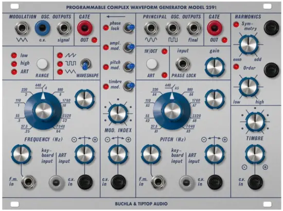
TIPTOP audio 259T Programmable Complex Waveform Generator
Oscillators
There are two oscillators: Modulation and Principal, both oscillators can be manually tuned via CV or Autotuned via ART.

Each oscillator has multiple outputs.
Specifications
Size: 34 HP – Depth: 25 mm
Power: +12V 260mA/ -12V 105mA
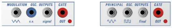
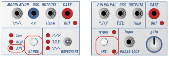
The Modulation Oscillator has a fixed Triangle waveform and a toggle selectable Signal output which can be a Triangle, Square or Sawtooth waveshape.
It can be switched from LFO (Low-Frequency Oscillator) mode to a high audio-rate oscillator. Additionally, it can be configured to receive incoming 1V/OCT or ART signals. A CV output is also available for the Modulation oscillator.

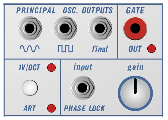
The Principal Oscillator has three audio outputs: a fixed Sine wave, a fixed Square wave and a Final output which provides infinite complex waveforms via the Timbre and Harmonics sections.
The Principal Oscillator runs at audio rate but its frequency range can be driven higher or lower with CV.
It can also be switched from 1V/OCT to ART.
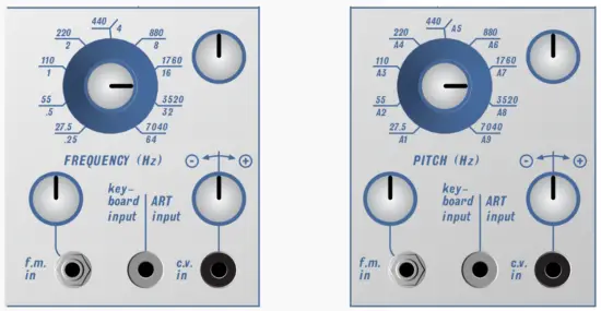
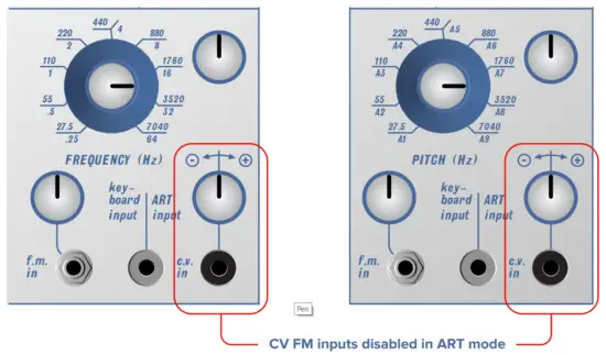
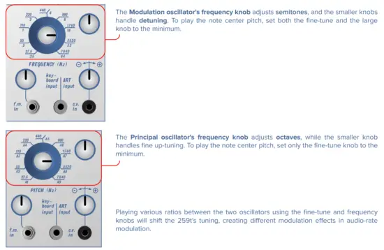
Both oscillators have a large Frequency control knob with a range of about 27.5hz which is the lowest A0 pitch on a piano up approximately 8 octaves to about 7040hz or A8 and octave above the highest A on a piano. The frequency figures surrounding the Frequency knob are approximate, not precise. As mentioned before their frequency ranges can be driven higher or lower with CV.
There is also a fine tune knob which covers a range of about an interval of a fifth.
Both oscillators have two CV inputs. The one with an attenuverter can add or invert the incoming CV. The one marked
Keyboard or ART can toggle to Keyboard mode which use 1V/OCT, or to ART.
Both oscillators can receive Audio FM and the amount of FM will be determined with the attenuator.
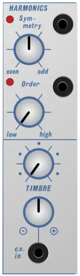
In Timbre/Harmonics section there are 3 wave shapers in that section and the knobs allow us to cross fade between their outputs and the VCO sine wave.
The wave shapers are:
Wave Folder
Sawtooth
M shape (can be consider as square)
The Order knobs cross fade between wave folder and / sawtooth and M shape. It is the final cross fade before the output.
When the Order is fully CCW the output is the wave folder and in that case the Timbre knob is the folding control and
Symmetry adds DC to the audio entering the folder thus altering its folding further to be asymmetric.
When Order is fully CW, timbre cross fade between the VCO sine wave and another cross fader of the sawtooth/M shape that is controlled by the Symmetry knob.
Yes there are tons of cross fades on this module and they are in series.
Since Order and Symmetry don’t have attenuators on their CV input this is good opportunity to use a 257t to process CV
before going to these inputs for more subtle control.
From the original manual:
“These three waveshape controls have a tremendous effect on the Final output signal and should be experimented with to discover the wide range of timbres this oscillator can produce before any signal processing.”
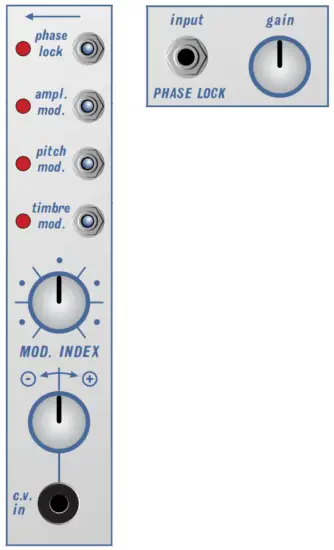
The Middle Modulation Section
Looking at the functions from the top down:
Phase Lock: the audio input jack has an attenuator pot which phase locks the frequency of this oscillator with the frequency of the input signal. If the frequency of the input signal is close to or lower than that of the oscillator it will cause the oscillator to “lock” onto the frequency of the input signal. If the input has a higher frequency the oscillator will “lock” onto the nearest subharmonic of the input frequency. This can be used to eliminate beating between two oscillators tuned in unison, octaves or harmonics.
In the Modulation section the switches are internal connections from Modulation oscillator to the Principal oscillator FM, Timbre section and Amplitude modulation.
The Amplitude switch set to the right has no effect. When switched to the left it will Amplitude Modulate the Principal oscillator with the Modulation oscillator as determined by the Mod Index setting of the attenuverter.
Likewise the Pitch (Frequency Modulation) switch set to the left engages its modulation.
Timbre Modulation is unique to this oscillator’s design and modulates the Timbre when set to the left.
Experiment with combining these modulation function in conjunction with the Mod Index attenuverter.
PITCH CONTROL WITH ART
The pitch of the 259t oscillators can be controlled manually with 1V/OCT CV or automatically for higher note accuracy using the module’s internal Autotune, activated by the ART switch. Please note that when set to ART, the CV FM inputs are disabled, while audio FM and all other inputs remain enabled.
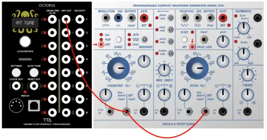
To demonstrate the use of ART, we will use Tiptop Audio’s Octopus ART module, though any other module that outputs ART, such as ART V/OCT, Model 264t, etc., can be used in the same manner. To activate the Autotuning for the first time, the module needs to learn the environment it is in, this process is called INITIAL TUNING.
INITIAL TUNING
When the module is fully warmed up (after about 30-40 minutes inside the case), patch the ART1 output from the Octopus to both ART input jacks on the 259t. You can use a Stackcable/mult or connect directly each oscilator from the ART1 and ART2 outputs on the Octopus. (Make sure both oscillators are set to ART).
Now, hold down the AUTO TUNE button on the Octopus until the display shows the “INT TUNE” message, then release the button. At this point, the 259t will start to tune itself. The LED will first turn off and then start blinking as it tunes the first oscillator.
Once the first oscillator finishes, the second oscillator will start tuning. Wait until the LED turns solid red on both oscillators.
This process can take anywhere from several seconds to several minutes. Do not interrupt the process. Once complete, the
259t can be used normally and will only need quick Auto Tuning from time to time.
The Initial Tuning procedure is recommended when the 259t is moved to a new case or environment, or if regular Auto Tuning (see later in the manual) takes a long time.
In this patch we demonstrate the use of the ART V/OCT module to quantize 245t CV steps into ART notes for the 259t.
The ART V/OCT module is a CV-to-ART Quantizer, generating ART notes for the 259t from any CV source in your system.
Additionally, all tuning procedures mentioned earlier with Octopus in this manual can be performed using the Quantizer.
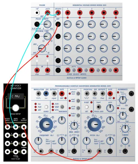
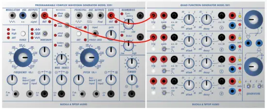
Patching With ART
The 259t is now ready to play in ART mode. Send notes from your ART module, the GATE OUT led on the 259t will flash. Plug the gate out into your 281t to trigger an envelope.
Auto Tuning
There are two different tuning options: Auto Tune and Initial Tune. We have already covered Initial Tune above.
Auto Tune is performed periodically to correct tuning to the current environment. It can be done often and is recommended when the system is already warm. Sending an Auto Tune command from the ART source module or by holding down the ART switch on the 259t will initiate Auto Tune. The ART lights will turn off, start flashing, and then become solid once tuning is done. It is recommended yet not mandtory to perform Auto Tuning occasionally to keep the oscillators in precise tuning.
If Auto Tuning takes longer than 3-4 minutes, it is recommended to perform a new INITIAL TUNING. None of these tuning procedures are destructive.
TRIMMERS
There are five trimmers on the 259t. All are factory-set and rarely need to be re-adjusted. TR1 and TR4 set the 1V/OCT tracking of the oscillators: TR1 for the modulator and TR4 for the principal oscillator. Adjusting these trimmers will affect the 1V/OCT scaling and ART tuning. If you make any adjustments, be sure to perform a new INITIAL TUNING in ART mode.
The other three trimmers adjust the principal oscillator’s sine wave shape and gain. To readjust, start with TR5, then move to TR2, going back and forth between them. Once the sine wave looks good, adjust the gain using TR3.
FIRMWARE UPDATE
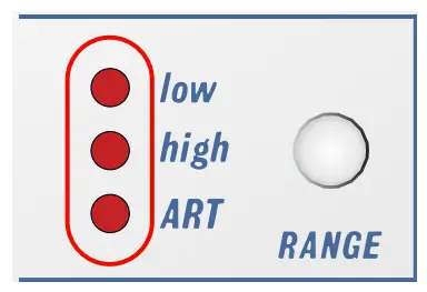
The MCU in the 259t is responsible for handling the Autotuning, some LEDs, and switches and can be updated with new firmware. To check the currently installed firmware, observe the modulator RANGE lights immediately after powering up; their order represents the firmware version. If a new firmware becomes available, it will be listed on the 259t page next to the user manual link.
The 259t has an SD card slot on the rear circuit board, which is used for firmware updates. Use an MSDOS FAT32 formatted card for the update.
- Download the firmware update file from the 259t webpage and unzip it. The file will be named image.hex.
- Copy the file to the SD card.
- Power off the case containing the 259t, remove the module from the case (keep the power cable attached!), and gently insert the SD card into the metal socket.
- Hold down the principal ART switch button and power on the case. When the LED flashes, release the button.

Documents / Resources
 |
TIPTOP audio 259T Programmable Complex Waveform Generator [pdf] Instruction Manual 259T Programmable Complex Waveform Generator, 259T, Programmable Complex Waveform Generator, Complex Waveform Generator, Waveform Generator, Generator |


