TANDELTA OQSxG2 System Integration User Guide

1 PRE-INTEGRATION CHECKLIST
READ THIS GUIDE THOROUGHLY BEFORE MAKING ANY SYSTEM CHANGES
1.1 Essentials prior to Data Integration
- Refer to the Sensor Quick Start Guide for instructions on where and how to install the Sensor and check its outputs.
- Make sure that the OQSxG2 Sensor is installed correctly on your asset (engine, gearbox etc.).
- Make sure that the OQSxG2 Sensor has been configured using the CADS software with the correct oil profile for your application.
1.2 Communication Protocols
The following communication protocols are available:
Analog: 4-20 mA
Digital: Modbus, CANopen, J1939
Make sure that you are familiar with your chosen protocol, and able to make the changes described in this document.
2 INTERPRETING DATA FROM THE TAN DELTA SENSOR
This Getting Started Guide gives an overview of how measurement data from a Tan Delta Oil Quality Sensor (OQSxG2) can be integrated into your existing monitoring or telematics system The Sensor outputs the following:

2.1 What is the Tan Delta Number? (TDN)
The Sensor expresses oil condition as a Tan Delta Number (TDN). The TDN scale extends from 1200 down to 0. Most clean oils start between 950 and 850 and will move down the scale as they degrade. Depending on the specific oil, the end of life (EOL) TDN will be between 600 and 300.
2.2 Warnings and Alarms
We recommend setting the following alerts based on the TDN output::

*NOTE: If any alert is triggered immediately at an installation or oil change this indicates that either the wrong oil has been used, or the wrong oil profile applied to on the Sensor.
2.3 Visualising your readings
In addition to integrating the OQSxG2 Sensor outputs into your control system, it can be beneficial to visualise the sensor outputs graphically, on your Control Room screen or system display. Examples of Tan Delta’s display platforms are shown on Page 5.
Tan Delta Display Examples As a guide, the examples below show how Sensor data is displayed visually on Tan Delta platforms.
Oil Quality Display Express OQDe Sensor data is show numerically on 7-segment displays, with an alert LED. In this case, we use additional proprietary analytics on board the display unit to generate event codes and calculate the remaining life of oil.

TD Online Within our online platform, TD Online, radial dials display the TDN and temperature values, with the warning and alarm areas highlighted.

3 COMMUNICATION PROTOCOLS
The Tan Delta Sensor supports the following communication protocols to connect to your telematics or control system: Analog: 4-20 mA Digital: Modbus, CANopen, J1939

To configure the Sensor for your chosen protocol, connect it to your PC/Laptop using the Configuration Cable and the Tan Delta CADS software.
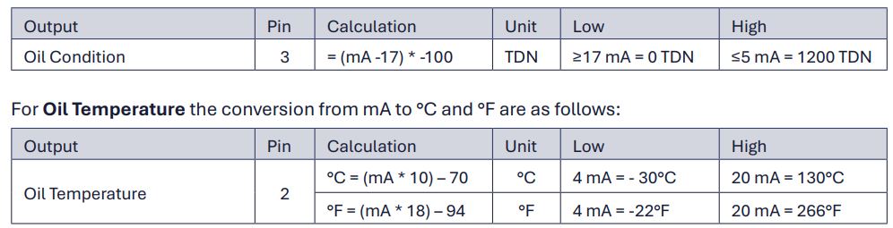
3.1 4-20 mA analog output
Refer to Fig. 3-1. The analog outputs are transmitted on Pin 3 (oil condition) and Pin 2 (oil temperature).
For Oil Condition, the range is 5-17 mA, and the conversion from mA to TDN is as follows:
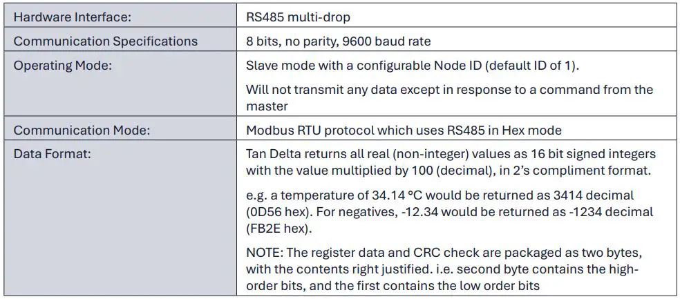
3.2 Modbus RTU digital communication
The following key data outputs can be accessed via Modbus:
- Oil Temperature (°C)
- Oil Temperature (°F)
- Oil Condition (TDN)
For a full explanation of the accessible queries and registers, see the User Guide.
The top-level specification of the Modbus communication used is below:
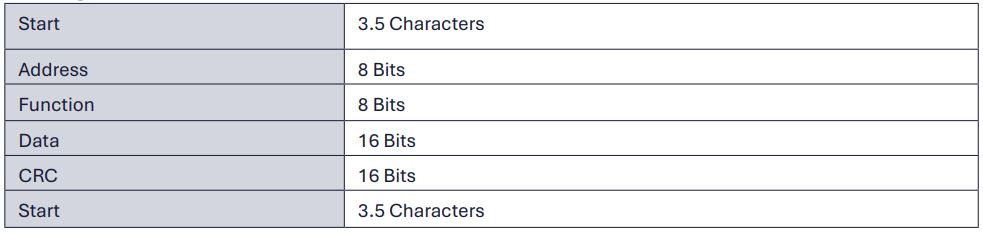
Message Format:
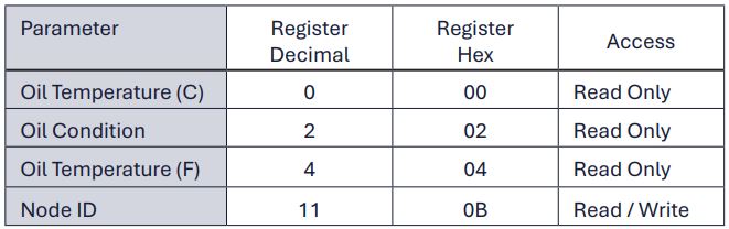
 Key Registers:
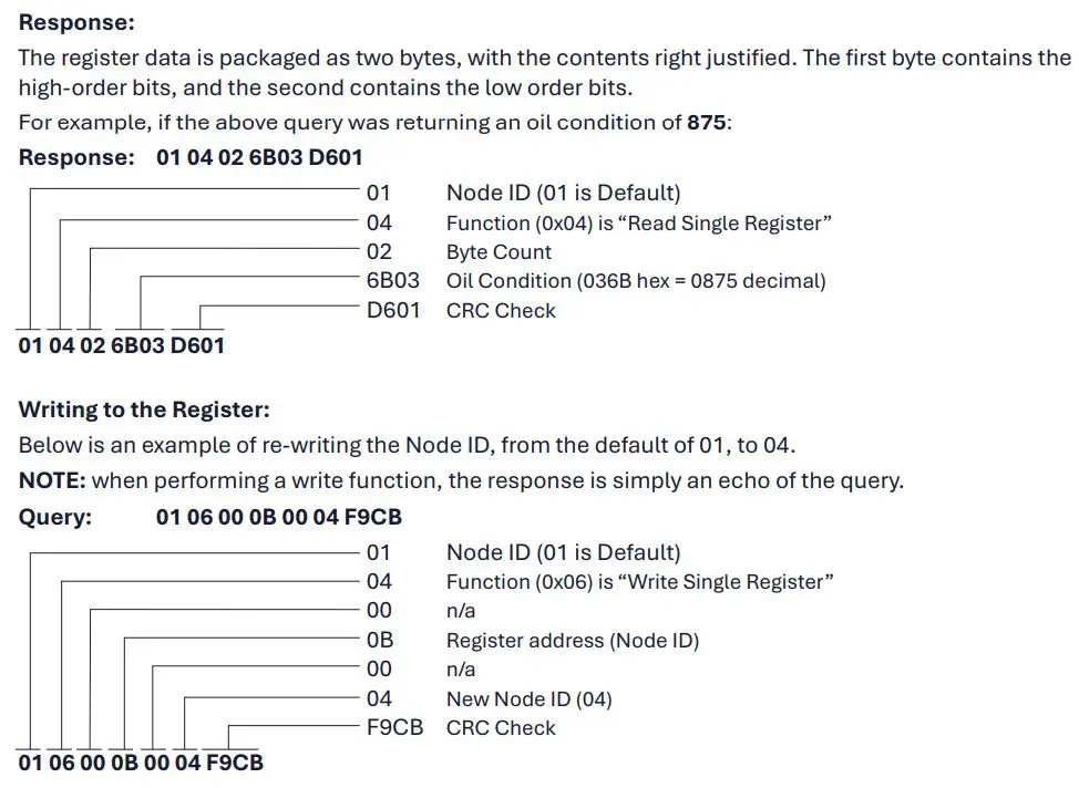
All information required from the Sensor is kept in registers, the key registers are as follows:
Communication Formats
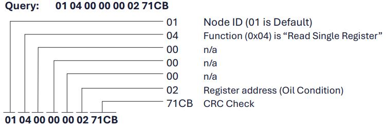
Query:
Read single register example reading oil condition:
3.3 CANbus digital communication
The Sensor uses a full CAN controller specified to conform with CAN 2.0B. Communication on CANbus can be done via CANOpen or J1939. The following key data outputs can be accessed via CANbus:
- Oil Temperature (°C)
- Oil Temperature (°F) (CANOpen only)
- Oil Condition (TDN)
For a full explanation of the accessible queries and registers, see the User Guide.
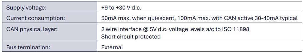
The physical CANbus specification is as follows:
CANOpen
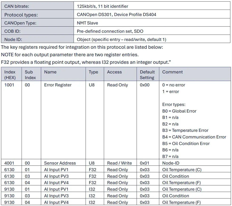
CANOpen Specification:
CAN Communication without CANOpen:
The Sensor can be used in CAN networks without full CANOpen functionality.
The Sensor can also operate in a network without a CANOpen Master, by setting the Sensor to “SelfStarting Mode”.
For detailed descriptions of the above processes, see the full Integration User Guide on our website: www.tandeltasystems.com/downloads
J1939
J1939 Specification:

Operation and Messaging:
On start-up, the Sensor will broadcast its J1939 Name/Address. Data is usually shown as little-endian, so the bytes will have to be reversed to get the above address. The Sensor will then begin automatic asynchronous data transmission, sending Oil Temperature and Oil Condition PGNs every 10s, as below:
E 18 FEFF 81 8 FF FF 002E FF FF FF FF
E 18 FEFF 81 8 FF FF FFFF FF 01 50 FF
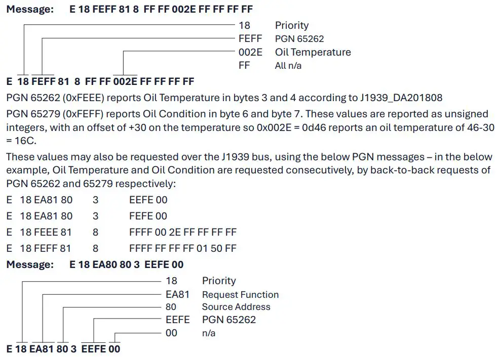
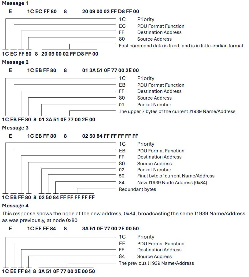
Node Address Change:
The 1939 Node Address may be changed by an external node by sending 3 messages to PGN 65240 using the Command Address function. The messages are shown below:
This example changes the Node Address of 50002E00770F513A to Node Address 0x84 Message 4 (below) shows the node at the new address, 0x84, broadcasting the same J1939 Name/Address as was previously, at node 0x80)
CONTACT DETAILS
Tan Delta Systems plc
1 Carrera Court
Church Road
Dinnington
Sheffield UK
S25 2RG
Tel: +44 (0)845 094 8710
support@tandeltasystems.com
Documents / Resources
 |
TANDELTA OQSxG2 System Integration [pdf] User Guide OQSxG2, OQSxG2 System Integration, OQSxG2, System Integration, Integration |