![]()
 KC Keypad Controllers
User Manual (V 1.0)
KC-4V KC Keypad Controllers
 Available in White, Black, and Brushed Aluminium
SY Electronics Ltd., 7 Worrall Street, Manchester, M5 4TH, United Kingdom
Tel: +44 (0)161 868 3450 – Web: sy.uk
Thank you for purchasing this product
The KC keypad controllers have been designed with the professional installers in mind.
The many extensive features will assist you in implementing the required system control quickly and help with integration, validation and maintenance.
Installation precautions
This product has special circuitry to protect it against moderate surges and static discharges. However, to ensure reliable operation and long service life, it is important to take the necessary precautions against any spikes, surges and static discharges.
Place the units away from sources of heat and/or moisture.
As much as possible, long cable runs should be routed away from any noisy sources and avoiding long runs in close proximity to AC mains cables.
The KC range of keypad controllers are easy to configure and are packed with a wide range of interfaces (RS232, RS485, Ethernet, IR, and digital I/O), making them an ideal controller either as a stand-alone device or as part a larger distributed control system.
The integrated IR learner simplifies the inclusion of any new device with IR requirements.
The Codeless methodology (No-code) enables easy configuration of the KC series by accessing a vast array of device libraries for effortless implementation. Complex functions are easy to implement without the need for any programming skills. For more sophisticated requirements, the units are programmed in Lua, achieving even more amazing functions simply and easily.
The easy to operate NebulaStudio® environment facilitates your requirements to achieve all the desired functions (codeless or coded). For a complex multi-controller system, the meshing facility makes the implementation easy, especially for future changes or upgrades.
The large elegant buttons are backlit with RGB LED which can be set to any colour /intensity required. Each button can be labelled, and protected with a clear cover cap. The versions with the rotary dial (volume control) also have a bar graph to show the set level.
The Ethernet / LAN port option facilitates control of IP enabled devices, as well as accepting PoE power for a more cohesive system.
Features
- Choice of 4, 6, 8 or 10 illuminated buttons (RGB)
- Rotary control (with push switch) versions
- Up to 6x RS232, 4x IR, and RS485 comm ports (using Flexi-ports)
- Optional Ethernet port with PoE
- 4x digital I/O ports (24V, 200mA – Over current & back EMF protected)
- Ethernet version can control up to 128 devices
- Built-In universal IR Learner (25-60KHz carrier)
- 32 concurrent event timers
- Rugged and resilient – All ports are fully protected
- Codeless – “No Code” methodology
- Can also program complex projects using Lua
- Standalone or meshed topology for multi controller installations
- The KC series keypads are programmed using NebulaStudio®
- 12V DC low power operation
Packing List
- KC-xx keypad.
- 12V 1A DC PSU, fitted with 2-way pluggable connector.
- Six 3-way pluggable connectors.
- Two 4-way pluggable connectors.
- Legend sheet for labelling the buttons.
- Clear caps to protect the buttons and its legend label.
- CRT (Cap Removal Tool)
Front Panel
KC-8V UK style front panel example. 
| Name | Description |
| Buttons | Legend-able back-lit (RGB) buttons. Any colour or brightness level |
| Rotary knob (Volume) | Rotary encoder with push switch (mute/unmute, on/off) |
| LED bar | LED volume bar indicator (5x Green, 1x Red) |
Back panel
For clarity, only the back-panel connections are shown (for all KC range). 
| Name | Description |
| Port 1 ~ Port 6 | Serial communication Ports 1 ~ 6 (ports 5 & 6 are Flexi-ports) |
| IR1 ~ IR4 | IR out ports – IR1, IR2 are on Flexi-Port 5 and IR3, IR4 are on Flexi-Port 6 |
| A B | RS485 connections on Port 6 |
| I/O Ports | Digital I/O Ports 1 ~ 4 (Input/Output) |
| 485 232 (slide switch) | RS485/RS232 Mode selection switch for Port 6, on the side of the rear cover |
| 120R – (slide switch) | RS485 termination selection switch, on the side of the rear cover |
| 12V | 12V DC PSU Input |
| IRL | IR sensor aperture for the IR Learning feature |
| USB-C | Programming port, on the side of the back panel |
| LAN (PoE) | RJ45 Ethernet port (optional), with Link (Yellow) & Activity (Green) LEDs |
Remove the desired legend from the legend sheet provided and affix it to the top of the button, then carefully fit the clear cap to protect the button legend.  Using the Cap Removal Tool (SY-CRT)
- Carefully insert the Cap Removal Tool between the button and faceplate opening.
- Gently pull the Cap Removal Tool (CRT) in an UPWARDS direction away from the faceplate surface. DO NOT attempt to lever off the cap, as this action may damage the button. You can gently try two or three sides to loosen the cap off the button.
- Please avoid excessive force and be gentle, as otherwise you may damage the button.
Features List
This table shows the features supported by each keypad type:
|
Product |
Buttons | Volume | RS232 | IR Out | I/O | RS485 | LAN |
IRL |
| KC-4V | 4 | 6 | 4 | 4 | ||||
| KC-6 | 6 | — | 6 | 4 | 4 | |||
| KC-6V | 6 | 6 | 4 | 4 | ||||
| KC-8V | 8 | 6 | 4 | 4 | ||||
| KC-10 | 10 | — | 6 | 4 | 4 |
![]() Feature is supported
Feature is supported
![]() Feature is not supported
Feature is not supported
![]() Optional PoE LAN port
Optional PoE LAN port
Using this Product
- The KC keypad controllers can be configured or programmed using the NebulaStudio®.
This is quite intuitive and flexible, allowing complex control and set ups in a very short time. The vast array of third-party device libraries simplifies the implementation. Adding new commands to the library is simple and quick.
Each button can have multiple functions, with any desired colour. The final program can be downloaded into the KC keypad controller via the USB-C port. - Using the legend sheet, each button can be individually labelled before fitting the clear cap to protect the label.
- Connect to the RS485 / RS232 serial, I/O, or IR ports as required.
- If required, connect the LAN port to the network using Cat5/6 cable.
- Connect the 12V DC power supply (Not required if PoE LAN port is used).
Using Built-In IR Learner
This feature is supported on all the KC series keypads. The IR Learner sensor is located beneath the IRL aperture on the rear of the keypad. Use NebulaStudio® to perform the IR learning and then assign the captured IR Remote commands to a library file.
Using the Serial Ports
The KC keypads have 6 Comm Ports, which can be set to the following parameters:
Baud rate:…………….. 600 to 115,200
Data bits:……………….. 8 or 9
Parity:………………. None, Odd or Even
Stop bits:………………….. 1 or 2
All the ports are protected against short circuit as well as ESD.
Flexi-Ports
Port 5 and Port 6, are multifunction serial Flexi-Ports:
| Port | RS485 | RS232 | IR |
| Flexi-Port 5 | — | ||
| Flexi-Port 6 |
The Flexi-port functions can be easily configured within NebulaStudio®. Flexi-Port 6 also
requires switch settings on the side of the back-panel as described on page 7.
Comm Ports 1-4
Comm Ports 1, 2, 3, and 4 are dedicated Bi-directional Full-duplex RS232 ports (Tx, Rx).
Flexi-port 5 – RS232 or IR
Com Port 5 is a Flexi-port and can be configured in 3 ways:
- Full-duplex RS232 (Tx, Rx)
- RS232 Tx with 1x Infra-Red output (IR2)
- 2x Infra-Red outputs (IR1, IR2). (See Flexi-port Examples).
Flexi-Port 6 – RS485, RS232, or IR
Comm Port 6 is a Flexi-port and can be configured in 4 ways:
- Half-duplex RS485
- Full-duplex RS232 (Tx, Rx)
- RS232 Tx with 1x Infra-Red output (IR4)
- 2x Infra-Red outputs (IR3, IR4). (See Flexi-port Examples)
There are two switches on the side of the back-panel that set the mode of Flexi-port 6.
When viewed with the faceplate at the bottom, the upper switch selects between RS485 or RS232/IR mode. The lower switch selects whether the RS485 data lines are terminated to 120R or are unterminated. This lower switch has no function when using RS232 or IR.
|
Port 6 – RS232/IR Mode |
Port 6 – RS485 Unterminated |
Port 6 – RS485 Terminated |
 The bottom switch has no function in this mode The bottom switch has no function in this mode |
 The bottom switch set to— position (Not Terminated) The bottom switch set to— position (Not Terminated) |
 The bottom switch set to 120R position (Terminated) The bottom switch set to 120R position (Terminated) |
For RS485 please note the following:
- The RS485 Termination should be set when the KC keypad is at the end of a cable run.
- The RS485 cabling should be a twisted pair to minimise induced interference.
- Both the A and B connections must be present for RS485 to operate reliably.
- When using shielded cable, connect the shield to the terminal Port 6 ground.
Flexi-port Examples
In each of the following diagrams, the top switch is the one furthest from the faceplate. The switch shown in grey has no function in the RS232 or IR modes.
Bidirectional RS232 (Tx, Rx)
This diagram shows Full-duplex RS232 connection to the Dsub-9 connector. Always refer to the third-party product manual to determine the actual connector type and wiring. All ports (1 ~ 6) can be connected in this manner (Set switch to RS232 mode for Port 6). Note: The bottom switch has no function when the top switch is set to RS232 mode.
RS232 Tx, with 1x IR on the same port
This configuration applies to port 5 and port 6.  Two IR Outputs
Port 5 and Port 6, each can be configured as two IR outputs:  RS485 on Port 6 Only
Port 6 can be set to RS485 mode by setting the two switches on the side of the KC keypad:  Note: The termination must only be set when the KC keypad is as an “end device” at the end of the RS485 cable run. Commands are assigned in the same manner as for RS232 commands in the NebulaStudio®.
Using the Digital I/O Ports
Each of the 4 digital I/O ports may be configured as either input or output:
- An input port can accept any voltage up to 24V DC.
- An output port can tolerate up to 24V and switches to 0V (max of 200mA sink current).
- Each output is overcurrent protected.
- Each output can directly drive a 12V relay coil (back EMF protected).
- The + output pin provides 12V supply to 200mA maximum (with Resettable fuse).
NOTE: In each of the following example diagrams, the referenced connections to I/O1 and I/O2 can also be applied to I/O3 and I/O4. The below are just some sample possibilities.
Driving Two Relays  No additional diode protection is required, as all KC I/O ports are fully protected against any back EMF.
One Relay and One Input Connection  Input 1 can alternatively be configured as an output port.
Digital and Switched input  The input 2 can alternatively be configured as an output port. Note that all I/O ports have internal pull-up resistor; as such direct connection to a switch is possible.
Using the Ethernet Port
The Ethernet option must be specified when ordering. The commands for the Ethernet port are programmed from NebulaStudio® to allow the KC keypad to send commands to IP controlled devices. The KC keypad can be powered from a PoE enabled Ethernet port.
Up to 128 network devices can be controlled by KC Keypad controller.
There are two indicator LEDs on the RJ45 connector:
- The Yellow LED indicates network activity and flashes whenever any network data traffic is detected.
- The Green LED indicates the presence of the Link carrier signal. It remains lit, indicating good connection with the connected network device.
RJ45 Cable Termination
It is recommended for the network cable to be wired at each end to T-568B specification: 
KC Panel Dimensions
For each of the following diagrams (shown from back), the Nominal Cutout dimensions gives the clearance required for the KC back panel. The images are not to actual size.
UK Faceplate  EU Faceplat
 US Faceplate
Specifications
General
| Buttons | Full colour RGB (16 million colours) |
| RS232 baud rates | All standard baud rates from 600 to 115,200 600 1,200 2,400 4,800 9,600 19,200 38,400 57,600 115,200 |
| RS232 settings | Data bits – 8 or 9 Party bit – none, even, or odd Stop bits – 1 or 2 |
| RS232 ports | Up to 6x RS232 ports (4x RS232, plus 2x Flexi-ports) |
| RS485 Port | Available on Flexi-port 6. (Selectable 120R termination) |
| IR outputs | Up to 4 IR outputs |
| I/O Ports | 24V DC, 200mA sink (to 0V) – (absolute max of 28V, 250mA) |
| I/O input impedance | 100K pull up to 12V |
| I/O + | 12V supply, Fused @ 200mA max. (Resettable fuse) |
| Ethernet | 10/100 BaseT – Can control up to 128 Ethernet devices |
| Ethernet PoE Voltage | 48V – 5 W max |
| IR Learner Frequency Range | 25 ~ 60 kHz carrier frequency |
| IR Out Carrier Range | 20 ~ 150 kHz |
| Power Consumption | 0.6 ~ 2.7 W (depending on the button LEDs brightness setting) |
| PSU | 12V 1A |
Environmental
| Operating Temperature | 0 ~ 40°C (32 ~ 104°F) |
| Operating Humidity | 10 ~ 90% RH (non-condensing) |
Physical
| Dimensions (WxHxD) | UK: 146 x 86 x 18.3 mm EU: 151 x 80 x 18.3 mm US: 115.8 x 114.4 x 18.3 mm (4.56 x 4.5 x 0.72 inches) Allow minimum depth (D) of 32mm, to allow for connectors and wiring. |
| Weight | 0.18 kg |
| Package Dimensions(WxHxD) | 233 x 60 x 129 mm (9.2 x 2.4 x 5.1 inches) |
| Package Weight | 0.45 kg |
KC Keypad Controller Models
KC keypad product numbering scheme: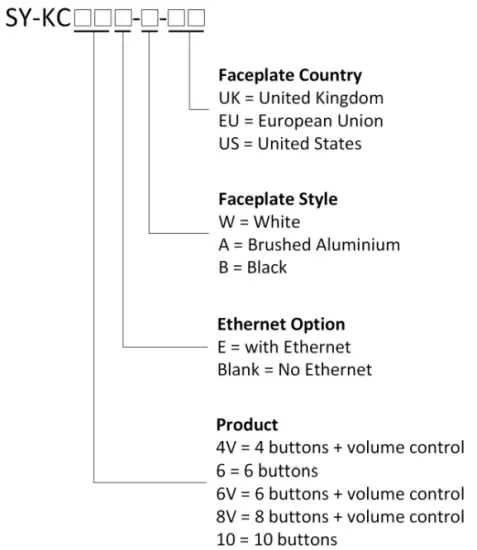
Examples:
| SY-KC6V-A-UK | 6 Button, with Rotary volume, Aluminium panel, UK style |
| SY-KC6-W-EU | 6 Button, White panel, EU style |
| SY-KC10E-B-US | 10 Button, with Ethernet, Black panel, US style |
| SY-KC8VE-W-UK | 8 Button, with Rotary volume, With Ethernet, White panel, UK style |
Safety Instructions
To ensure reliable operation of this product as well as protecting the safety of any person using or handling these devices while powered, please observe the following instructions.
- ONLY USE the power supply provided. If an alternate supply is required, check the voltage, polarity and that it has sufficient power to supply the device it is connected to.
- DO NOT operate this product outside the specified temperature and humidity range given in the above specifications.
- Ensure there is adequate ventilation as this product generates heat while operating.
- Repair of this product should only be carried out by qualified professionals as this product contains sensitive devices that may be damaged by any mistreatment.
- Only use this product indoors and in a dry environment. DO NOT allow any liquids or harmful chemicals to come into contact with this product.
After Sales Service
- Should you experience any problems while using this product, firstly refer to the Troubleshooting section in this manual and/or your local dealer before contacting SY Technical Support.
- When calling SY Technical Support, please provide the following information:
- Full Product Name and Model Number
- Product Serial Number
- Details of the fault and any conditions under which the fault occurs.
- This product has a two year standard warranty beginning from the date of purchase as stated on the sales invoice. For full details please refer to our Terms and Conditions.
- The SY Product warranty is automatically void under any of the following conditions:
- The product is already outside of its warranty period
- Damage to the product due to incorrect usage or storage
- Damage caused by unauthorised repairs
- Damage caused by mistreatment of the product
- Please direct any questions or problems you may have to your local dealer before contacting SY Electronics.
![]()
Documents / Resources
 |
sy KC-4V KC Keypad Controllers [pdf] User Manual KC-4V, KC-6, KC-6V, KC-8V, KC-10, KC-4V KC Keypad Controllers, KC-4V, KC Keypad Controllers, Keypad Controllers, Controllers |