![]() Icemaker Information ICB INTEGRATED SERIES (T & C-SWS #5623000)
Icemaker Information ICB INTEGRATED SERIES (T & C-SWS #5623000)
ICEMAKER SYSTEM INFORMATION
This Series units utilizes a Nidec-Servo® icemaker. Its operation is not complex, but understanding its components and operation cycle assists a Service Technician to make proper diagnosis of problems.
![]() WARNING
WARNING
TO AVOID ELECTRIC SHOCK, ALWAYS DISCONNECT ELECTRICAL POWER TO UNIT WHEN SERVICING ICEMAKER.
NOTES:
- The
 key on the control panel activates the icemaker system. If the ice cube icon is not displayed on the LCD, the icemaker system is OFF.
 - To allow ice to freeze fully and reduce effects of low water pressure, the electronic control disables the icemaker system for 45 minutes after each ice harvest.
- The icemaker system is disabled when the unit is in Sabbath Mode.
ICEMAKER COMPONENTS
Following are descriptions that explain the function of each icemaker component. The components are diagramed in Figure 5-1 on the next page.
Support – The support is the housing around the electrical components and wire connections.
The support is attached to the ice mold.
Mounting Plate – The drive motor, holding switch, water valve solenoid switch, timing gear, timing cam and water fill adjusting screw are attached to the metal mounting plate. The mounting plate is then attached to the support.
Drive Motor – 220-240 volts AC supplied to the drive motor causes the motor to operate. The motor has a single output shaft with a small gear. The motor gear drives/spins the timing gear.
Timing Gear – The timing gear is driven/spun by the drive motor gear and is attached to the timing cam.
Timing Cam – The timing cam is attached to the timing gear and the ice ejector is inserted into the center of the timing cam. As the timing cam rotates, high and low spots on the cam operate the water valve solenoid switch and the holding switch. The timing cam also moves the lever arm side to side and rotates the ice ejector.
Ice Mold – The ice mold is where the eight crescent shaped ice cubes are formed.
Mold Heater – The mold heater uses 110 watts to thaw the ice free from the mold.
Ice Ejector – The drive end of the ice ejector is “D” shaped to fit into the “D” shaped hole in the timing cam.
It has eight blades which rotate and sweep the ice from the mold cavities during the ejection phase of the cycle.
Ice Stripper – The stripper is attached to the dumping side of the mold, serving as a decorative side cover and it also prevents ice from falling back into the mold.
Bearing/Inlet – The bearing/inlet is attached to the ice mold, opposite the support. Water enters the bearing/ inlet and is directed to the ice mold. The bearing/inlet also supports the ice ejector at the end opposite the timing cam.
Thermostat – The thermostat is a single-pole, singlethrow, bi-metal switch. At -9 °C (15°F) ± 1.5°C it closes, starting the ice ejection phase.
Thermal-Mastic – A substance similar in appearance to grease that is applied between the thermostat and the ice mold. Its purpose is to increase thermal conductivity between the mold and the thermostat.
Lever Arm and Shut-off Arm – The lever arm is moved side to side by two revolutions of the timing cam. As it moves, it raises and lowers the shut-off arm and operates the shut-off switch to control the quantity of ice production. If the shut-off arm comes to rest on top of the ice in the storage bin during either revolution, the shut-off switch re mains open, stopping ice production at the end of that revo lution.
Water Valve Solenoid Switch – A single-pole, doublethrow type switch that allows electricity to the water valve solenoid, opening the valve, during the fill cycle.
Holding Switch – A single-pole, double-throw type switch that ensures completion of a revolution once the icemaker has been energized.
Shut-off Switch – A single-pole, double-throw type switch that stops ice production when the ice bin is full.
TCO (Thermal Cut Out) – The TCO is thermal protection device in the wire harness that would open in the event of mechanical failure, thus protecting against over heating. (The TCO is not shown in diagram.)
ICB INTEGRATED SERIES (T & C-SWS #5623000) Icemaker Information

(For reference only. Individual components are not available for Service. If problems with the icemaker are discovered, the entire icemaker must be replaced)
ICEMAKER OPERATION
The following series of electrical schematics illustrate a typi cal icemaker cycle of operation. Below each schematic is a diagram indicating the approximate location of the ice ejector and ice level arm during the phase the schematic indicates.
Freeze Phase of Ice Making Cycle (See Figure 5-2)
- The ice mold is filled with water.
- The thermostat is open.
- No icemaker components are energized.

Start of the First Revolution (See Figure 5-3)
- The water in the ice mold has turned to ice.
- At -9 °C (15°F) ± 1.5°C the thermostat closes.
- The mold heater is energized through the thermostat.
- The drive motor is started through the thermostat and “normally closed” terminal of the holding switch.
- The ice ejector begins to turn and the shut-off arm begins to rise.

First Revolution Continued (See Figure 5-4)
- The holding switch is tripped by the timing cam to “normally open” thus holding power to the motor.
- The mold heater remains energized through the thermostat.
- The shut-off arm begins to rise.

First Revolution Continued (See Figure 5-5)
- The ice ejector reach the ice in the mold.
- The ice releases from the mold as the ejector blades begin to rotate the cubes out.
- The drive motor remains energized through the holding switch.
- The mold heater remains energized through the thermostat.
- As the shut-off arm rises, the shut off switch is tripped to “normally closed”, and then the shut-off arm begins to lower.

First Revolution Continued (See Figure 5-6)
- The ice has released from the mold.
- The motor remains energized through the holding switch.
- The shut-off arm is lowered and the shut off switch is tripped to “normally open”.
- The water valve solenoid switch is tripped by the timing cam, but the solenoid is not energized because the thermostat is still closed and energizing the mold heater. (Electric current follows the path of least resistance.)
End of First Revolution (See Figure 5-7)
- The water valve solenoid switch is tripped by the timing cam back to “normally open.”
- The timing cam trips the holding switch to “normally close,” which ends the first revolution, but the thermostat is still closed, so the motor is again started.
- The mold heater remains energized through the thermostat.
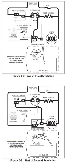
Start of Second Revolution:(See Figure 5-8)
- The water valve solenoid switch is tripped by the timing cam back to “normally open.”
- The timing cam trips the holding switch to “normally close,” which ends the first revolution, but the thermostat is still closed, so the motor is again started.
- The mold heater remains energized through the thermostat.
Second Revolution Continued (See Figure 5-9)
- The mold heater has warmed the thermostat, so the thermostat opens, and the mold heater is de-energized.
- If the shut-off arm comes to rest on top of the ice in the storage bin (as illustrated), so the shut-off switch re mains in the “normally closed” position.
- The motor remains energized through the holding switch.

Second Revolution Continued (See Figure 5-10)
- The water valve solenoid switch is tripped by the timing cam. This time the solenoid is energized because the thermostat is open. The water solenoid is open for approximately seven seconds, filling the ice mold with water.
- the mold heater is energized through the solenoid switch and holding switch.
End of Ice making Cycle (See Figure 5-11)
- The water valve solenoid switch is tripped by the timing cam back to “normally open” ending the water fill.
- The timing cam trips the holding switch to “normally close,” which ends the second revolution.
- The thermostat is still open, so it does not start the drive motor.
- If the shut-off arm has come to rest on top of the ice in the storage bin (as illustrated), the shut-off switch re mains in the “normally closed” position. This interrupts power from reaching the thermostat, until sufficient ice has been removed from the storage bin allowing the shut-off arm to lower.
NOTE: To allow ice to freeze fully and reduce effects of low water pressure, the electronic control system disables the icemaker system for 45 minutes after each ice harvest.

MANUALLY STOPPING ICE PRODUCTION
Ice production can be manually stopped two ways:
- Press the key on the control panel so that the ice cube icon is not displayed on the LCD.
- Position the ice-level/shut-off arm in the up/OFF position (See Figure 5-12).
MANUALLY STARTING THE ICEMAKER
NOTE: To allow ice to freeze fully and reduce effects of low water pressure, the electronic control disables the icemaker system for forty-five (45) minutes after each ice harvest. To bypass this 45 minute dwell for service purposes, press the ![]() key at the control panel to switch the system OFF, then again to switch it back ON.
key at the control panel to switch the system OFF, then again to switch it back ON.
Manual Start Procedure:
- Pry the icemaker front cover from the support using a flat-blade screwdriver or coin.
- With a flat-blade screwdriver, turn the drive gear counterclockwise until the holding switch is activated, completing the circuit to the drive motor (this is about a 1/8 turn). (See Figure 5-13) The icemaker then completes its cycle automatically.
NOTE:
If after 1/4 turn the icemaker is not running on its own, it may be in the 45 minute dwell period, the 3 minute power interruption from opening and closing the door/drawer switch, or there is an electrical or mechanical problem.

ADDITIONAL ICEMAKER SERVICE NOTES:
- Manual icemaker water fill time/volume adjustment is not possible on the Integrated Series, as this is a function of the electronic control system and cannot be changed.
- The icemaker system is de-energized for three (3) minutes after a door/drawer switch is opened then closed. This feature is to help prevent an ice harvest if someone has removed the ice bucket for a brief period of time. Because of this three (3) minute icemaker power interruption, the door/drawer switch(es) must be closed for three (3) minutes after they are opened in order to check voltage to the icemaker. or cause icemaker to cycle.
ICEMAKER FAULT TESTING
Bypass 45-minute dwell by pressing ![]() key to OFF, then again to ON. Now, depress and hold the freezer light switch for three (3) minutes and manually start icemaker by turning driver gear counter-clockwise with screwdriver.
key to OFF, then again to ON. Now, depress and hold the freezer light switch for three (3) minutes and manually start icemaker by turning driver gear counter-clockwise with screwdriver.
- If icemaker starts & finishes two cycles without filling:
(NOTE: If >-9°C, icemaker only completes 1 revolution.)
a. Visually inspect electrical connections at icemaker & valve. Repair if necessary.
b. Check the operation of both valves with test cord, if they do not open, replace. c. Check thermostat. (Open: 9°C ±3°C, Close: -9°C ±1.5°C). Replace icemaker if defective.
d. With icemaker in park position, check solenoid switch terminals “C” & “NO” for continuity. With ejector between 8:00 & 10:00 position, check solenoid switch terminals “C” & “NC” for continuity. If no continuity for either terminal check, replace icemaker. - If icemaker starts but does not finish cycle:
a. With icemaker in park position check holding switch terminals “C” & “NC” for continuity. Then with icemaker ejector between 10:00 & 12:00, check holding switch terminals “C” & “NO” for continuity. If no continuity for either terminal check, replace icemaker. (Refer to enclosed wiring diagram)
b. With icemaker in park position check shut-off switch terminals “C” & “NO” for continuity. With ejector between 12:00 & 2:00 check shut-off switch terminals “C” & “NC” for continuity. If no continuity for either terminal check, replace icemaker.
c. Check mold heater for 480 Ohms ± 10%. If outside range, heater is bad, replace icemaker. If heater checks OK, thermostat is bad, replace icemaker. - If icemaker motor does NOT start:
a. Lower shutoff arm
b. Check motor operation with test cord. If motor doesn’t run, replace icemaker.
c. Check power to and from icemaker rocker switch (if present). Reconnect or repair connection or replace switch as necessary.
d. Check for power from control board to icemaker. If power is present check & repair connection. If no power, replace control board.
QUICK REFERENCE
- Water Fill Time – 5.4 +.6, -.4 seconds
- Fill Tube Heater Ohm: 10173 Ohms ± 10%
- Mold Heater Ohm: 480 Ohms ± 10%
- Water Valve Ohm: 1058 Ohms ± 10%
- Isolation Water Valve Ohm: 2645 Ohms ± 10%
- Thermostat Open/Close – Open: 9°C ±3°C Close: -9°C ±1.5°C
- Water Pressure Needed: 20-120 psi constant
ICEMAKER TROUBLESHOOTING
No / Slow Ice Production
- Ice maker system switched OFF. Switch system ON.
- Shut off arm in up/OFF position. Move to ON position.
- Freezer too warm. Check temperature & see troubleshooting guide in service manual.
- Poor airflow over icemaker. Remove obstructions.
- Ice cube jam. Remove ice & check water fill setting.
a. Water fill setting too low (< 5 sec’s).
b. Water fill setting too high (> 6 sec’s). - Water froze in inlet tube. Remove ice from tube. Check for power from control board to fill tube heater when unit is in defrost; Fill tube heater = 10173 Ohms ± 10%.
- Water supply not constant 20-120 psi. Instruct customer.
- Water line to unit pinched/kinked/clogged. Repair line.
- Saddle valve not installed correctly. Reposition.
- Saddle valve not fully open. Open valve fully.
- Icemaker wire/connections loose/broken. Repair wiring.
- Water valve wire/connections loose/broken. Repair wiring.
- Defective water valve. Valve =1058 Ohms ± 10%. Replace valve.
- Defective isolation water valve. Valve =2645 Ohms ± 10%. Replace valve.
- Thermostat wire/connections loose/broken. Repair wiring.
- TCO overheated or shorted. Fix cause or replace icemaker.
- See Icemaker Fault Testing.
No Water Fill
- Water supply switched OFF. Switch supply water line ON.
- Water line to unit pinched/kinked/clogged. Repair line.
- Saddle valve not installed correctly to supply line.
Reposition.
- Water froze in inlet tube. Remove ice from tube. Check for power from control board to fill tube heater; Fill tube heater = 10173 Ohms ± 10%.
- Water valve wire/connections loose/broken. Repair wiring.
- Defective water valve. Valve = 1058 Ohms ± 10%. Replace valve.
- Defective isolation water valve. Valve = 2645 Ohms ± 10%. Replace valve.
Overflows / Ice Block Forms in Bucket / Oversized Cubes
- Icemaker not level. Level icemaker.
- Unit not level. Level unit
- Water supply not constant 20-120 psi. Instruct customer.
- Water froze in inlet tube. Remove ice from tube. Check for power from control board to fill tube heater; Fill tube heater = 10173 Ohms ± 10%.
- Water fill setting too low (< 5 sec’s).
- Water fill setting too high (> 6 sec’s).
- Defective water valve. Valve = 1058 Ohms ± 10%. Replace valve.
Ice Cubes Hollow or Small
- Icemaker not level. Level icemaker.
- Unit not level. Level unit
- Water supply not constant 20-120 psi. Instruct customer.
- Water fill setting too low (< 5 sec’s).
- Too little thermalmastic on thermostat. Add thermalmastic.
- Defective thermostat (Open = 9°C ±3°C, Close = -9°C ±1.5°C). Replace thermostat.
Too much Ice
- Shut off arm/linkage bent/broken. Repair or replace arm/linkage.
- If ejector blades rotate with arm in up/OFF position = Icemaker faulty. Replace icemaker.
#7040739 – Revision C – November, 2016
Documents / Resources
 |
SUB-ZERO T and C-SWS ICB Integrated Ice Maker [pdf] Instruction Manual T and C-SWS, T and C-SWS ICB Integrated Ice Maker, ICB Integrated Ice Maker, Integrated Ice Maker, Ice Maker, Maker |