STMicroelectronics UM3055 STSW-ONE Graphical
User Interface User Manual

Introduction
This user manual describes the operation of the ST-ONE® Graphical User Interface, optionally associated with STEVAL-PCC020V2.1, the USB to UART interface board.
The STEVAL-PCC020V2.1 is an interface board used to connect a Windows® based PC with digital power supply controllers such as ST-ONE, STNRG012, or STNRG011. The layout and the behavior of the interface board are described in the ST-ONE datasheet.
The GUI allows to update the ST-ONE embedded firmware, calculate the main board’s components, monitor in real time the status of the digital controller, and tune specific parameters according to customer needs.
GUI features
- Running on Windows XP (.NET 4.0 framework needed), Windows 7, 8, and 10
- Board components setup
- Real time monitor of the digital controller status
- Connection to ST-ONE using either direct standard COM port or through STEVAL-PCC020V2 board.
Figure 1. ST-ONE GUI main form

GUI installation
The ST-ONE GUI installation is performed by a dedicated installer. The installer does not remove previous versions of the GUI: if an equivalent version is already installed on the PC, it is removed when the installer is launched, and a new installation is required.
Double-click on setup.exe to launch the installer. When the form below appears, select Next to continue.
Double-click on setup.exe to launch the installer. When the form below appears, select Next to continue.
Figure 2. ST-ONE installer – welcome page

In order to move on with the installation, the license agreement has to be accepted.
Figure 3. ST-ONE installer – license agreement

It is recommended to install the ST-ONEGUI inside a dedicated STMicroelectronics folder on disk C:, as shown below. In case the user do not own the administration rights, it is recommended to install the ST-ONE GUI in a folder where administration rights are not requested
Figure 4. ST-ONE installer – path selection

Once the installation is concluded, the tool can be launched.
GUI introduction
2.1 GUI features
The ST-ONE GUI is a tool developed to help a developer to set up and monitor the behavior of the ST-ONE. At a glance, it allows to:
- Program flash memory
- Calculate main board components
- Read event history data (for example, fault history).
2.2 GUI startup screen
The main form is shown in Figure 5.
The GUI is subdivided in 3 areas:
The GUI is subdivided in 3 areas:
- Tool bar: it allows to select the desired actions to be performed on ST-ONE
- VCC control & basic actions: it contains UART controls
- Traces and status: Internal debug traces and status bar showing the current status of ST-ONE.
Figure 5. ST-ONE GUI startup screen

2.3 Connection management
The communication between the PC and ST-ONE, through PCC020V2, can be implemented with two different configurations. Connect cable A between the PC and PCC020V2, cable B between PCC020V2 and ST-ONE:
Figure 6. Configuration 1

Figure 7. Configuration 2

Caution: AC voltage must always be disconnected during VCC generation, otherwise there would be a conflict between VCC generated by the interface board and the ST-ONE converter output.
The procedures below are recommended:
- For flash programming:
– Disconnect AC source.
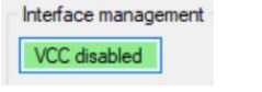
– Connect the interface board and launch the GUI by pressing VCC button. The VCC button changes to VCC Enabled.
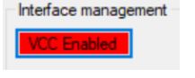
– Perform operations.
– Disconnect VCC on the GUI by pressing VCC button. The VCC button changes to VCC Disabled.
– Connect AC source
2.4 Establishing the communication link, boot modes
Before being able to perform any operation, the user must ensure a correct communication channel with the ST- ONE device.
First of all, the ST-ONE device must be supplied.
First of all, the ST-ONE device must be supplied.
- If a direct UART connection is used, the ST-ONE chip must be powered externally.
- If the STEVAL-PCC020 is used, this is straight forward, the user has to just click on the VCC Enable button.
If the communication is successfully established:
- The ST-ONE boot ROM sends a READY message
The status bar displays Communication OK and the boot and application versions are displayed in the task bar too.
Figure 8. Successful communication with ST-ONE

Note:
- The GUI forbids to Enable VCC if VCC is already detected (supply running).
Figure 9. VCC generation forbidden

- When VCC is engaged, if it goes down below a given threshold or above the OVP threshold, VCC is automatically disengaged to protect the interface board.
Boot modes:
At startup, the internal boot ROM checks the status of the Rx line.
- If it has asserted to ground, the MCU does not start the application. This mode is called the “rescue” mode and it is used to update the application firmware
- Otherwise, if there is a valid application firmware image stored in flash, the MCU branches to the application, which is the normal mode of operation.
Note:
If the STEVAL-PCC020 interface board is not used, the user must apply the following sequence:
- VCC off, tied UART_RX line to ground in order to select rescue mode.
- Apply VCC
- Release UART_RX line
- Press AskReady button to check if the link has been successfully established.
If the STEVAL-PCC020 board is attached, boot mode can be selected (rescue mode or normal mode)
Figure 10. Rescue mode boot: the MCU remains in boot ROM state

Note that in this case, the application firmware detected that the ST-ONE chip is powered from the secondary side (so by the STEVAL-PCC020 interface in our case).
At startup, the GUI automatically detects the COM port to be used (the GUI selects the CP2102 based VCP).
In case of multiple CP2102, the user has to manually select the right COM port through the COM port menu.
In case of multiple CP2102, the user has to manually select the right COM port through the COM port menu.
Figure 11. COM port selection

It is possible to open/close the COM port using the dedicated icon:
Figure 12. COM port open and close

Some sections of the GUI can operate even without a connected ST-ONE board, but real time monitoring is not available.
Once the right COM port is selected, the GUI tries to communicate with the interface board microcontroller with the selected speed, see Figure 2. In case the connection is not correctly established, modify the UART speed or switch between the interface connection selected (for example, from GPIO to CC or from CC to GPIO).
Once the right COM port is selected, the GUI tries to communicate with the interface board microcontroller with the selected speed, see Figure 2. In case the connection is not correctly established, modify the UART speed or switch between the interface connection selected (for example, from GPIO to CC or from CC to GPIO).
Figure 13. Traces during GUI connection

Note:
If the GUI does not find a SiLabs based VCP, an error message pops up.
Check in the Device Manager that the SiLabs VCP is correctly recognized. (see Figure 14)
Check in the Device Manager that the SiLabs VCP is correctly recognized. (see Figure 14)
Figure 14. SiLabs VCP in the device manager

2.5 Settings
The GUI settings are accessible by clicking the Settings icon.
Figure 15. Available settings panels


The Save Settings button allows to save the settings into the config.xml file, located in: “.\\xml\\config.xml”, maintaining the same choices for the next time the GUI is opened.
Table 1. GUI settings

GUI features
3.1 Application flash parameters editor
Figure 16. Application flash parameters editor

In applicative mode or rescue mode, this feature is used to update persistent application parameters:
- read and write the application flash parameters
- store and recall the parameters to disk
- edit the parameters in a convenient way.
There are various sections for the parameters:
- App setup: defines the behavior of the application boot
- App code parameters: configures traces, default voltage settings, and protection
- USB PD: related to USB PD compliance and parameters as per specification
- Power: firmware parameters of the power section.
The parameters description is outside the scope of this document, and they are subject to change with the application firmware evolution, so a dedicated document is available. ST-ONE
Figure 17. Application flash parameters editor window

Note:
- In order to Read or Write parameters, the ST-ONE chip must be supplied (otherwise an error message pops up)
- It is also possible to update the flash parameters in application mode but this is not recommended, furthermore, some parameters might not be taken into account before reset.
3.2 Setup board – wizard
This module has been designed to guide the user during the first approach to the board’s electrical components and ST-ONE behavior.
It is required to fill the first table, Figure 18 , with the theoretical desired values of the application under analysis; a brief description of each parameter is reported inside the Info Box. If the inserted value exceeds the range an error message is reported. The inserted values are automatically implemented in the mathematical model after the start button is pressed. If values are not consistent with each other (for example, a minimum greater than a maximum), an error box is displayed.
It is required to fill the first table, Figure 18 , with the theoretical desired values of the application under analysis; a brief description of each parameter is reported inside the Info Box. If the inserted value exceeds the range an error message is reported. The inserted values are automatically implemented in the mathematical model after the start button is pressed. If values are not consistent with each other (for example, a minimum greater than a maximum), an error box is displayed.
Note: No further modifications of these parameters are considered after the simulation steps have started. In order to make changes effective, a new simulation has to be performed by pressing the start button again.
Figure 18. Power section design table

3.2.1 Bulk capacitor
This tab allows to compute the valley voltage and to obtain the capacitor’s behavior curves, selecting:
- The mains frequency, choosing between 50 Hz or 60 Hz basing the application
- The bulk capacitor (capacitance and tolerance)
- The maximum output power (the default value is imported from the power section design table, but the value can be modified to analyze changes in the graph).
Press Compute to obtain the results.
The valley voltage box assumes a red background color if the result cannot be accepted, otherwise a green
background confirms that the choice is correct.
In order to create a readable chart, current values have been modified before plotting with a stretching factor (*20) and an offset (+ 20). Thus, the values reported on the Y axis have to be considered valid for voltages only. All the raw results for both voltages and currents, to perform a partial plotting, are contained inside \output\ST-ONE_CapResults.txt.
Figure 19. Capacitor computations form

3.2.2 Clamping capacitor and transformer
This tab allows to compute fundamental quantities related to the transformer. The mains voltage and the output voltage may be defined directly inserting the value with the correspondent box or selecting an operating condition among the choices in the ComboBox.
Figure 20. Clamping capacitor and transformer design form

The user can choose a direct or a reverse approach through the CheckBox, depending on which parameters are essential. The direct one starts from the primary and leakage inductances to obtain the switching frequency. On the contrary, the reverse approach computes the leakage and the primary inductances and from the primary- leakage ratio and the switching frequency.
Press Compute to obtain the results.
For both cases, the width of the bump and the clamping capacitance are calculated.
Press Compute to obtain the results.
For both cases, the width of the bump and the clamping capacitance are calculated.
3.2.3 Zero current detector
This tab allows to compute the zero current detection (ZCD) advance time.
Basing on the value suggested by the previous tab, a clamping capacitance has to be selected, satisfying the constraints on Tbump: it has to be kept between a range of (12-18) % of the switching period. If this requirement is not satisfied an error box is shown when the next button is pressed.
Press Compute to obtain the results.
Figure 21. ZCD design form

3.2.4 Loop
This tab allows to compute the loop gains at constant current and constant voltage, starting from the fundamental loop parameters.
Press Compute to obtain the results
Press Compute to obtain the results
Figure 22. Loop parameters design form

3.2.5 Waveforms
This tab allows to generate the waveforms representing the device’s behavior. When pressing the Compute
button, all the simulation results are saved on a file GeneralWave_wizard_x_.txt and summarized inside the table.
The second column of the table is based on the current-voltage conditions specified within the boxes. From the third to the last column simulation results on the four fundamental corners are reported, respectively:
- Maximum line voltage, maximum output voltage
- Minimum line voltage, maximum output voltage
- Maximum line voltage, minimum output voltage
- Minimum line voltage, minimum output voltage
Press Compute to obtain the results. The expand chart button shows a larger version of the computed graph. The data represented within the chart are the ones related to the Actual conditions. In order to update the graph starting from the new conditions, press again Compute, then Expand Chart.
Figure 23. Waveform parameters simulation form.

3.2.6 ACF design
This form exploits a recap of the design parameters selected or obtained through previous computations. When Calculate Flash parameters is pressed, the power parameters section of the application flash form is updated with the new values.
Note: In order to be effective, the application flash update has to be saved before closing the form.
Figure 24. Active clamp flyback design recap

3.3 Firmware update
Figure 25. Firmware update menu and window

The onboard STM32 firmware can also be updated from the GUI; the last firmware version associated with the GUI is always provided inside the GUI delivery. When the GUI boots, it tries to locate the interface board and then identifies the firmware version: if too old, to obtain a correct setup an update is required.
Figure 26. Firmware update confirmation window

- If the embedded firmware version is later than or equal to the v. 2.4, the process is automatic, no user action (for example, jumper connection) is required.
- On the other hand, if the embedded firmware has been corrupted or there is no firmware at all, it is necessary to connect a jumper on J2 and hit the Reset button (user has to follow up instructions).
- Once the firmware has been updated, the GUI reboots the board and the new firmware can be used.
Revision history
Table 2. Document revision history

IMPORTANT NOTICE – READ CAREFULLY
STMicroelectronics NV and its subsidiaries (“ST”) reserve the right to make changes, corrections, enhancements, modifications, and improvements to ST products and/or to this document at any time without notice. Purchasers should obtain the latest relevant information on ST products before placing orders. ST products are sold pursuant to ST’s terms and conditions of sale in place at the time of order acknowledgment.
Purchasers are solely responsible for the choice, selection, and use of ST products and ST assumes no liability for application assistance or the design of purchasers’ products.
No license, express or implied, to any intellectual property right is granted by ST herein.
Resale of ST products with provisions different from the information set forth herein shall void any warranty granted by ST for such product.
ST and the ST logo are trademarks of ST. For additional information about ST trademarks, refer to www.st.com/trademarks. All other product or service names are the property of their respective owners.
Information in this document supersedes and replaces information previously supplied in any prior versions of this document.
© 2023 STMicroelectronics – All rights reserved
Documents / Resources
 |
STMicroelectronics UM3055 STSW-ONE Graphical User Interface [pdf] User Manual STEVAL-PCC020V2.1, UM3055 STSW-ONE, UM3055 STSW-ONE Graphical User Interface, STSW-ONE Graphical User Interface, Graphical User Interface, User Interface |