
StarTech.com 4×4 HDMI Matrix Switch with Audio

FCC Compliance Statement
This equipment has been tested and found to comply with the limits for a Class B digital device, pursuant to part 15 of the FCC Rules. These limits are designed to provide reasonable protection against harmful interference in a residential installation. This equipment generates, uses and can radiate radio frequency energy and, if not installed and used in accordance with the instructions, may cause harmful interference to radio communications. However, there is no guarantee that interference will not occur in a particular installation. If this equipment does cause harmful interference to radio or television reception, which can be determined by turning the equipment off and on, the user is encouraged to try to correct the interference by one or more of the following measures:
- Reorient or relocate the receiving antenna.
- Increase the separation between the equipment and receiver.
- Connect the equipment into an outlet on a circuit different from that to which the receiver is connected.
- Consult the dealer or an experienced radio/TV technician for help
This device complies with part 15 of the FCC Rules. Operation is subject to the following two conditions: (1) This device may not cause harmful interference, and (2) this device must accept any interference received, including interference that may cause undesired operation.
Changes or modifications not expressly approved by StarTech.com could void the user’s authority to operate the equipment.
Industry Canada Statement
This Class B digital apparatus complies with Canadian ICES-003.
Cet appareil numérique de la classe [B] est conforme à la norme NMB-003 du Canada.
CAN ICES-3 (B)/NMB-3(B)
Use of Trademarks, Registered Trademarks, and other Protected Names and Symbols
This manual may make reference to trademarks, registered trademarks, and other protected names and/or symbols of third-party companies not related in any way to StarTech.com. Where they occur these references are for illustrative purposes only and do not represent an endorsement of a product or service by StarTech.com, or an endorsement of the product(s) to which this manual applies by the third-party company in question. Regardless of any direct acknowledgment elsewhere in the body of this document, StarTech.com hereby acknowledges that all trademarks, registered trademarks, service marks, and other protected names and/or symbols contained in this manual and related documents are the property of their respective holders.
Introduction
Packaging Contents
- 1 x HDMI Matrix Switch (VS424HDPIP)
- 1 x Remote control
- 1 x Mounting brackets
- 1 x Universal Power Adapter (NA/UK/EU/AUS)
- 1 x Quick Install Guide
System Requirements
- Up to 4 x HDMI-enabled Video Source Devices (i.e. computer, Blu-ray Player)
- Up to 4 x HDMI-enabled Display Devices (i.e. television, projector)
- Up to 8 x M/M HDMI cables for displays and video sources
Product Diagram
Front View
- IR Sensor
- ower Button / LED
- Menu Button / LED
- Menu Operation Buttons / LEDs
- Output Selection Buttons / LEDs
- Input Selection Buttons / LEDs
- Mode Selection Button / LEDs
- Save Button / LED
- Lock Button / LED
- Recall Button

Rear View
- HDMI Input Ports
- HDMI Output Ports
- LAN Port
- USB Service Port
- RS232 Serial Port
- Power Adapter Port

Hardware Installation
- Connect up to four HDMI cables (not included) from each of your HDMI video source devices (i.e. computers, Blu-ray Players) to each of the HDMI input ports on the matrix switch.
- Connect up to 4 HDMI cables (not included) from each HDMI output port on the matrix switch to the HDMI input ports on your display devices (i.e. televisions, projectors).
- Connect the power adapter from an available power outlet to the Power adapter port the Matrix switch.
- (Optional) If you would like to control your Matrix Switch with RS232, connect a DB-9 pin serial cable (not included) from the RS232 serial port on the matrix switch to your RS232 serial port on your computer system.
- (Optional) If you would like to control your Matrix Switch over your network, connect a network cable (not included) from the LAN port on the matrix switch to an available LAN port on your network device.
Hardware Operation
Matrix Operation
- Press the Mode button repeatedly until the Mode LED is solid to indicate Matrix Mode.
- Press the Output select button (that corresponds with the lettered output display) you wish to select.
- Press the input select button (that corresponds with the numbered input display) you wish to output on your selected output display.
- Your selected video input will now be displayed on your selected video output. Repeat steps 2- 3 for each video output you wish to adjust. Each output setting must be made individually.
Dual Mode Operation
- Press the Mode button repeatedly until the Mode LED is unilluminated to indicate Dual Mode.
- Press output A/B and then press corresponding input 1/2.
For example: If you press output A then press input 1, output A will display the input 1 image on the left side. If you then press output B followed by input 2, output A will display the input 2 image on the right side. Both output A and B will have an identical image.
Note: Dual A group are output A and B, Dual B group are output C and D. Each group will output the same image simultaneously. - To switch the audio source between output A or B, Press button A or B for 3 seconds.
- To switch the audio source between output C or D, Press button C or D for 3 seconds.
TV Wall Mode Operation
- Press the Mode button repeatedly until the LED is blinking to indicate TV Wall Mode.
- Press the input select button (that corresponds with the numbered input display) you wish to output on all displays.
Note: Audio will Output on the device connected to Video Output A only
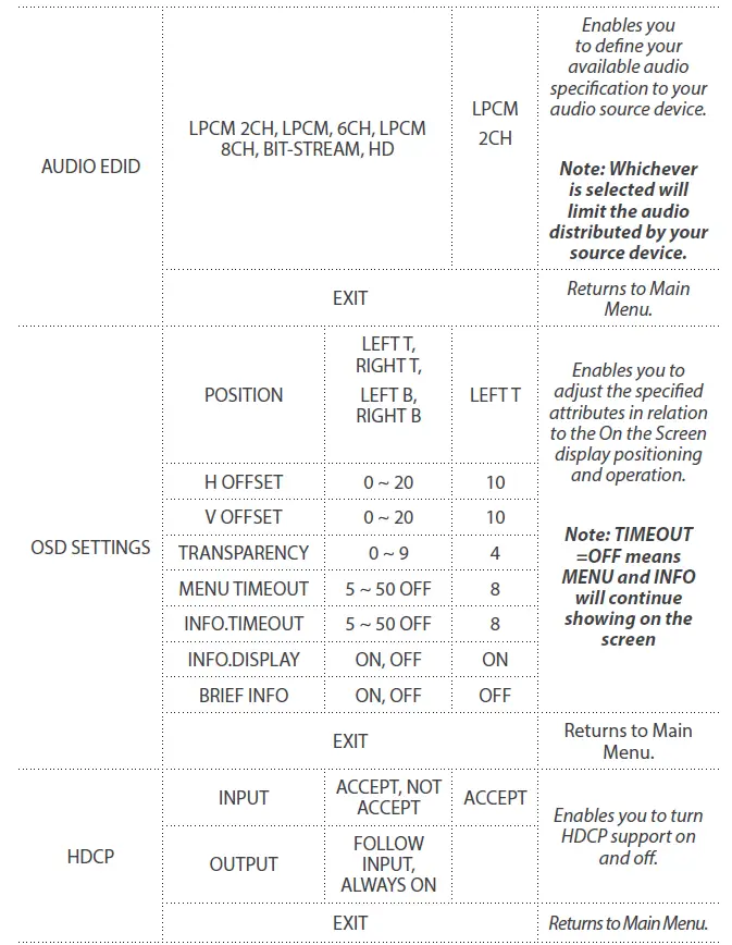
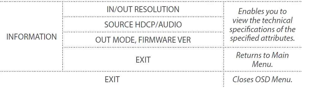
The OSD menu gives you access to advanced functionality. The below table lists each OSD menu option. The description field outlines the functionality of each menu selection.


IR Remote Control Operation
An IR remote control is included with the VS424HDPIP for hassle-free remote operation. Please review the legend below for a detailed description of each remote control function.
- Power: Press this button to switch on the device or press it again to set it to standby mode.
- Info: Press this button to show the device’s firmware version.
- Out A~D and In 1~4: Press out¬put A~D and then press input 1~4 to select display input. For example: press Out A then press In 1, output A will display input 1’s image.
- MATRIX/DUAL/WALL: Press to switch between Matrix mode, Dual mode and TV Wall mode.
- Lock: Press once to lock the keypad and remote control, press 3 seconds again to re¬lease the lock function.
- Mute: Press this button to mute the audio from HDMI output port.
 : Press these buttons to scroll through the OSD selec¬tion and press OK to enter and confirm the setting.
- Exit: Press this button to exit the OSD menu or the OSD settings.
- Menu: Press this button to enter into the OSD menu.
- 1024×768/720p/1080p: Press these hotkeys to switch between each resolution.
- AL/AR/BL/BR: When in Dual mode, press these hot keys to switch the audio channel in the Left or Right side for Dual A and Dual B groups.
- SAVE: To save the customized input and output corresponding settings.
- Press the “Matrix/Dual/Wall” button to select mode status.
- Press each output channel A~D and then press the corresponding input channel 1~4.
- Press “SAVE”, then input 1~4’s LED will illuminate at the same time, then press remote control FAV.1~FAV.4 to save to the system memory.
- FAV.1~FAV.4: Press favorite hotkeys 1~4 to bring up the customized screen save settings.
IR Remote Control Dip Switch
If you’re using multiple switches in the same location you can configure up to three remote controls on different IR addresses to avoid interference with each other. To adjust the remote control, open the Remote control back cover and adjust the dip-switch ON/OFF to match IR address setting in the OSD menu. The factory default setting is 0.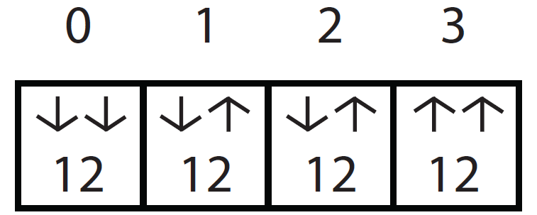
You must then adjust the switch itself using the OSD menu, to the specific number you’ve set your remote control to. To adjust the IR addressing of the switch itself please access the below setting in the OSD menu.
Others -> IR addressing
RS232 Serial Operation
RS232 Pin Assignment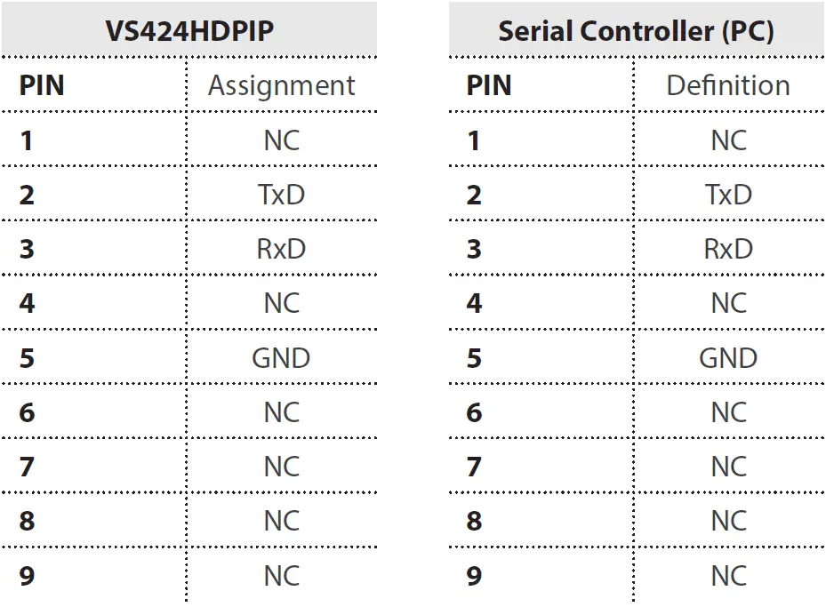
RS232 Protocols
- Baud Rate: 115200bps
- Data Bit: 8 bits
- Parity: None
- Flow Control: None
- Stop Bit: 1
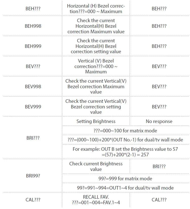
RS232 Telent Commands
Note: All commands will be not executed unless followed with a carriage return (0x0D) and commands are case-sensitive.
IP Operation Using Web Browser
Before you begin:
- Power Status must be set to on, and source status must be unlocked
- Ensure step 5. of hardware Setup has been completed.
- Obtain the IP address of the VS424HDPIP using the OSD menu. Access the following sub-menu:
ETHERNET -> IP
Your IP address will be displayed next to IP.
Note: The switch supports DHCP and it is activated by default. As a result if you connect it to a piece of network equipment that supports DHCP your IP address will automatically change. If your network equipment does not support DHCP your default IP address will be 192.168.5.155
Access IP Operation Web GUI
- Open your web browser.
- In the address bar type the IP address obtained from your OSD menu, and press enter.
- The VS424HDPIP web GUI is now displayed.
Operate your VS424HDPIP using the Web GUI
The web GUI enables you to remotely operate your VS424HDPIP with basic and advanced functionality. The below sections outline the features and navigation of the Web GUI.
Operation Pane
The operation pane gives you a high-level overview as well as access to basic switch operations. The Operation pane is always visible at the top of every page in the Web GUI.
The Information-in and information-out sections gives you an overview of the current connected video source and display devices.
The Status section enables you to power off the device.
The Source section enables you to select your desired mode as well as define which video source devices will be shown on each display.
The Save/Factory section enables you to save and action the customized input and output corresponding settings.
Advanced Menu
The Advanced menu is available on the left hand side of the GUI, and enables you to navigate between advanced sections of operation.
Descriptions outlining navigation as well as the available functionality for each tab are listed below.
Image Adjust
By default, the Image Adjust tab is the first window displayed when the web GUI is opened. If you would like to access the Image Adjust tab, and have navigated away from the Window, click Image Adjust tab from the side menu.
The Image Adjust tab enables you to define the specific attributes listed for optimal picture quality based on the requirements of your application.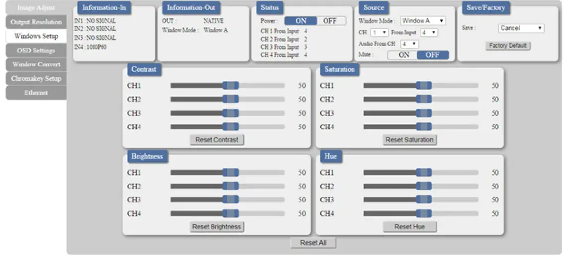
Note: In Matrix mode, all four pictures adjust simultaneously.
In Dual/TV Wall mode, each picture can adjust individually and support the individual last memory feature.
Output Resolution
To access the Output Resolution tab, click Output Resolution on the side menu.
The Output Resolution tab enables you to set your desired output resolution from the available drop-down menu.
Notes:
- 1080i@50/60 are supported in Matrix mode only.
- Selecting NATIVE enables the VS424HDPIP to use EDID to determine the best output resolution automatically.
OSD Settings
To access the OSD settings tab, click OSD Settings on the side menu.
The OSD settings tab enables you to adjust the specified attributes in relation to the On the Screen display positioning and operation.
Note: TIMEOUT =OFF means MENU and INFO will continue showing on the Screen.
Window Convert
To access the Window Convert tab, click Window Convert on the side menu.
The Window Convert tab enables you to implement transition effects while switching between video sources.
Chromakey Setup
To access the Chromakey Setup tab, click Chromakey setup on the side menu.
The Chromakey Setup section enables you to isolate a particular color for chroma keying special effects.
Ethernet
To access the Ethernet tab, click Ethernet on the side menu.
The Ethernet section enables you to define Network communication protocols for remote operation.
Technical Support
StarTech.com’s lifetime technical support is an integral part of our commitment to provide industry-leading solutions. If you ever need help with your product, visit www.startech.com/support and access our comprehensive selection of online tools, documentation, and downloads.
For the latest drivers/software, please visit www.startech.com/downloads
Warranty Information
This product is backed by a two year warranty.
In addition, StarTech.com warrants its products against defects in materials and workmanship for the periods noted, following the initial date of purchase. During this period, the products may be returned for repair, or replacement with equivalent products at our discretion. The warranty covers parts and labor costs only. StarTech.com does not warrant its products from defects or damages arising from misuse, abuse, alteration, or normal wear and tear.
Limitation of Liability
In no event shall the liability of StarTech.com Ltd. and StarTech.com USA LLP (or their officers, directors, employees or agents) for any damages (whether direct or indirect, special, punitive, incidental, consequential, or otherwise), loss of profits, loss of business, or any pecuniary loss, arising out of or related to the use of the product exceed the actual price paid for the product. Some states do not allow the exclusion or limitation of incidental or consequential damages. If such laws apply, the limitations or exclusions contained in this statement may not apply to you.
Hard-to-find made easy. At StarTech.com, that isn’t a slogan. It’s a promise.
StarTech.com is your one-stop source for every connectivity part you need. From the latest technology to legacy products — and all the parts that bridge the old and new — we can help you find the parts that connect your solutions.
We make it easy to locate the parts, and we quickly deliver them wherever they need to go. Just talk to one of our tech advisors or visit our website. You’ll be connected to the products you need in no time.
Visit www.startech.com for complete information on all StarTech.com products and to access exclusive resources and time-saving tools.
StarTech.com is an ISO 9001 Registered manufacturer of connectivity and technology parts. StarTech.com was founded in 1985 and has operations in the United States, Canada, the United Kingdom and Taiwan servicing a worldwide market.
FREQUENTLY ASKED QUESTION
Up to 16 stereo audio sources can play simultaneously to 16 audio outputs with the Control4 Audio Matrix Switch. Individual gain control, as well as separate bass and treble control, can be used to improve each output zone.
Multiple HDMI devices can be connected to numerous monitors, televisions, etc. For a home audio-visual arrangement, having an HDMI multiplex would allow for the connection of many source devices to various screens.
The switch is HDCP 2.2 compliant with your HDMI-enabled devices and supports HDMI 2.0 (4K@60) signals. Additionally, a soundbar or audio receiver with an HDMI ARC connector can be connected via the ARC bypass option (Input-4 & Output).
Multiple source devices can be connected to a single HDMI input using an HDMI switch. A numbered input on the switch is connected to each source device.
Unfortunately, using an HDMI switch will prevent you from simultaneously using several screens. Instead, a switch only toggles between many displays, enabling you to quickly select the one display you want to use with a certain device.
To send audio signals from several sources to various locations or zones, a matrix mixer is employed. When using a matrix mixer, you are able to combine several output signals or buses, such as aux sends, the L/R main mix, subgroups, etc., to create unique mixes.
You need a separate matrix switch if you want your video sources to be accessible on screens around your home or if you have a multi-display room, like this fantastic home media room.
The phrase “matrix device” generally refers to a drug delivery system in which the drug is disseminated inside a polymer network, either as solid drug particles or as molecularly. At least four different sorts of devices can be imagined in this scenario.
Any input can be switched at any time to any output, including multiple outputs, using matrix switchers. A matrix switcher can send DisplayPort, HDMI, DVI, 3G-SDI, HD component, S-video, or composite video signals, together with or without stereo audio, depending on the type.
There aren’t any significant drawbacks to adding an HDMI switch to your device if you choose a higher-quality switch. The signal quality won’t be diminished by HDMI switching. Additionally, there shouldn’t be any additional visual lag. HDMI switches typically enable ARC as well (Audio Return Channel).
In brief, an HDMI switch accepts several sources and enables you to select (switch) between them while connecting just one cable to your TV. We’ll go into more depth later. As you’ve probably already guessed, a splitter divides a single signal among several HDMI wires.
The device whose signal is transmitted to the display is changed by operating the switch using its remote control or manual controls. The output can be switched to the active device automatically with switches that support automatic HDMI switching.
Since there is no need to decide where to run electricity, installing a passive switch may be simpler. A powered switch, however, might be more effective if you require a longer cable run or if a specific HDMI device doesn’t produce a strong signal.
There shouldn’t be any lag as long as you use a decent, active HDMI switch, which are generally more expensive. Unlike passive switches, active switches are powered by an external power source via an AC adapter.
Your power strip should get the power cords. If desired, use a VGA port to connect the first monitor to your computer instead of an HDMI port. Repeat the process with the second monitor.


