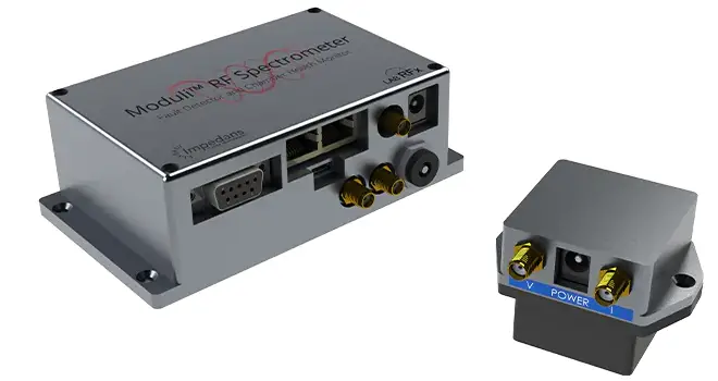
SPECTRA SP42RF Precision Atmel RF Module

Hardware
The RF module works with the Atmel RF transceiver AT86RF233 and the 2.4GHz Front End SE2431L-R from Skyworks. The range on the module PCB that contains the RF transceiver and the connected antenna network is covered with a metal shield. The antenna is a chip Antenna.
Technical Data only for the Atmel AT86RF233 Transceiver itself, not valid for the complete module.
The AT86RF233 is the transceiver of the Atmel RF module. The following list contains the technical data of the Atmel AT86RF233 in combination with the Front End.
- Operating frequency range 2405MHz to 2480MHz
- O-QPSK modulation
- Channel Bandwidth 3.2MHz
- Max output power 24dBm
- Operating temperature range -20°C to +50°C
- Operating voltage range 2V to 3.8V
- 250kbps data rate
- 4 wire SPI
- IEEE802.15.4 compliant DSSDSseband
Atmel RF AMP Module Connection Description
In the following table, the connector pins of the Atmel RF module are listed and described.
| Name | Description |
| VDD | Power supply (1.8…. 3.8V) pin |
| MISO | Master system SPI reception/module/transceiver SPI transmission pin |
| SILK | SPI clock (generated by the master system, max. 5MHz) |
| RESET_n | System reset (inverted) |
| IRAQ | Interrupt request signal output |
| SLP_TR | Controls sleep, deep sleep, transmits start |
| CPS | Front End module select for RF_TX_RX |
| nasal | Module/transceiver chip select pin (inverted) |
| MOST | Master system SPI transmission/module/transceiver SPI reception pin |
| GND | Ground pin |
SPI Interface
The communication with the Atmel RF module transceiver is realized with a 4-wire SPI (CS_N, CLK, SPI_IN, SPI_OUT). The following picture illustrates the SPI timing requirements.

The following table describes the parameters of the picture above.
| Parameter | Description | Min | Typ | Max | Unit |
| t1 | /SEL failing edge to MISO active | 180 | ns | ||
| t2 | SCLK falling edge to MISO out | 25 | ns | ||
| t3 | MOSI setup time | 10 | ns | ||
| t4 | MOSI hold time | 10 | ns |
RF Operation
This section describes the possible RF operations of the AT86RF233 a, and there, with the Atmel RF module.
This device complies with part 15 of the FCC Rules. Operation is subject to the following two conditions:
- This device may not cause harmful interference, and
- this device must accept any interference received, including interference that may cause undesired operation.
Changes or modifications not expressly approved by the party responsible for compliancvoidds the user’s authority to operate this equipment.
Specs
- Operating frequency range 2400MHz to 24835MHz
- O-QPSK modulation
- Channel Bandwith 3.2MHz
- Rated peak power: 4.5 dBm EIRP
- Operating temperature range -20°C to +50°C
- Operating voltage range 2.8V to 3.6V DC
- 250kbps data rate
- 4 wire SPI
- IEEE802.15.4 compliant-DSS baseband
IEEE802.15.4 Frame Format
The communication is based on the physical layer of the IEEE802.15.4 standard, but the AT86RF233 can be configured for handling the MAC layer of the IEEE802.15.4 standard. The following picture illustrates the IEEE802.15.4 frame format, which is supported by the AT86RF233 transceiver.

RF Configuration Options
The following list contains possible configurations that can be set by SPI commands at the AT86RF233 transceiver on the Atmel RF module.
- Rated peak power: 4.5 dBm EIRP
- Output power can only be set by the firmware with SPI commands, so the end-user is not able to change the output power.
- RF Channel Selection (2400 … 24835MHz)
Following the IEEE802.15.4 standard f, the following channels can be selected:
- 2400 … 24835MHz in 5Mhz steps
- (k=1: 2405MHz, k=2: 2410MHz, k=3: 2415Mhz, … , k=15: 2475MHz, k=16: 2480MHz)
- A clear channel assessment is supported that allows a simple listen-before-talk implementation.
RF Operations Modes
The RF module supports different operation modes. Overall,l different power modes are supported, which limits the module in possible operation but allows improvement of power consumption.
The following picture illustrates the different power modes, the transitions between the power modes, and the power consumption of the modes.

Active Operation Modes
In the active mo,e the RF module transceiver can be only in one of the following states.
- Idle
- TX: Transmission (The next frame in the transmission queue is sent out, then Idle or Reception mode (dependent on AT86RF233 configuration). This state is kept only so long, as AT86RF233 is transmitting a frame.
- RX: Reception
The states can be changed with SPI commands. The simplified state table with transition times illustrates the possible operation mode changes.
| State | Command | Condition | Next
State |
Transition
Time |
| Idle | reenable != 0 | RX | 192µs | |
| RX | reenable == 0 | Idle | ||
| RX | STXON | TX | 192µs | |
| RX | SROFF | tractive == 0 | Idle | |
| TX | frame sent && rxenable != 0 | RX | 190µs | |
| TX | frame sent && rxenalbe == 0 | Idle | ||
| TX | SROFF | tractive == 0 | Idle |
Documents / Resources
 |
SPECTRA SP42RF Precision Atmel RF Module [pdf] Instruction Manual 2BDMX-SP42RF, 2BDMXSP42RF, SP42RF Precision Atmel RF Module, SP42RF, Precision Atmel RF Module, Atmel RF Module, RF Module, Module |
