![]() MB41
MB41
AIoT Edge Controller
User Manual
Brief Introduction
MB41 is an AIoT Edge Controller based on S905X4 processor, it has multiple interfaces include HDMI, TF card, 10/100M Ethernet, Wi-Fi (BT integrated), I2C, UART, SPI, GPIO, USB3.0, USB2.0 (OTG), RTC, etc.
Specification
| Feature | MB41 – AIoT Edge Controller |
| PCB Size / Overall Size | 65mm x 40mm |
| Display | 1x HDMI (Type D) |
| Ethernet | 1x Ethernet (10/100) |
| Wi-Fi | 2T2R, IEEE 802.11b/g/n/a/ac |
| BT | 2.1/3.0/4.2/5.0 |
| USB | 1x USB 3.0 Type C 1x USB 2.0 Type C (Can be used as power input port) |
| Serial | 2x UART (TTL 3V3 Power level) |
| I2S | 1x I2S (3.3V Level) |
| I2C | 2x (3.3V Level) |
| GPIO | 11x GPIO (3.3V Level) |
| ADC | 1x (range 0 ~1.8V) |
| RTC | With super capacitor for RTC power supply (over 2 hours) |
| LED | 1x LED (Green): power indication 1x LED (Blue): status indication (controlled by software) |
| Power Requirements | +5VDC Input |
| Operating Temperature | 0°C to +55° |
| Weight | 50g |
| Accessories | N/A |
Interfaces
3.1 Hardware interface 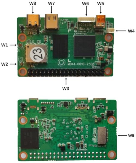
| Label | Name | Description |
| W1 | Wi-Fi with BT ANT | IPEX-1 |
| W2 | Wi-Fi only ANT | IPEX-1 |
| W3 | 40PIN | GPIO, I2C, I2S, UART, ADC |
| W4 | RTC battery Connector | For external RTC battery input |
| W5 | HDMI connector | Type D |
| W6 | Ethernet | 10/100M (need extra transformer) |
| W7 | USB 3.0: 5V/0.9A | Type C |
| W8 | USB 2.0: 5V/0.5A | OTG, power input |
| W9 | TF card | Half size |
3.2 Description
3.2.1 ANT (W1)
IPEX – 1 (Dual Band Wi – Fi and Bluetooth Combo)
Manufacturer:Beijing Huatong Jiaye Technology Co., Ltd
Type/Model: Dual band fan-shaped rubber rod omnidirectional antenna
Bluetooth (BR/EDR/LE):maximum PK gain: 3.09 dBi
2.4G WIFI:Maximum PK gain: 3.09 dBi
5G WIFI: Maximum PK gain: 4.56 dBi
3.2.2 ANT (W2)
IPEX- 1(Dual Band Wi – Fi Only)
Manufacturer:Quectel Wireless Solutions Co., Ltd.
Type/Model: WIFI FPC Antenna
2.4G WIFI:Maximum PK gain: 2.0 dBi
5G WIFI: Maximum PK gain: 5.3 dBi
3.2.3 40PIN (W3)
| Pin | Pin Description | Pin | Pin Description |
| 1 | 3V3 | 2 | 5V |
| 3 | GPIOZ_14 | 4 | 5V |
| 5 | GPIOZ_15 | 6 | GND |
| 7 | GPIOZ_13 | 8 | GPIOD_0 |
| 9 | GND | 10 | GPIOD_1 |
| 11 | GPIOZ_8 | 12 | GPIOZ_7 |
| 13 | GPIOZ_9 | 14 | GND |
| 15 | GPIOZ_3 | 16 | GPIOZ_2 |
| 17 | 3V3 | 18 | GPIOC_7 |
| 19 | GPIOH_4 | 20 | GND |
| 21 | GPIOH_5 | 22 | GPIOZ_12 |
| 23 | GPIOH_7 | 24 | GPIOH_6 |
| 25 | GND | 26 | SARADC_CH0 |
| 27 | GPIOA_14 | 28 | GPIOA_15 |
| 29 | GPIOD_9 | 30 | GND |
| 31 | GPIOZ_11 | 32 | GPIOD_10 |
| 33 | GPIOD_6 | 34 | GND |
| 35 | GPIOZ_6 | 36 | GPIOD_8 |
| 37 | GPIOZ_10 | 38 | GPIOZ_4 |
| 39 | GND | 40 | GPIOZ_5 |
I2C:
PIN3( SDA), PIN 5( SCL)
PIN27( SDA), PIN28( SCL)
UART:
PIN8(TXD ), PIN10(RXD )
PIN36(TXD ), PIN29(RXD )
ADC:
PIN26
SPI:
PIN19( MOSI), PIN21(MISO), PIN23(SCLK), PIN24( CS )
I2S:
PIN12(BCLK), PIN35(LRCK), PIN38(DIN), PIN40(DOUT)
GPIO:
40PIN number (7,11,13,15,16,18,22,31,32,33,37)
PIN18 is Open Drain
3.2.4 RTC Backup Battery (W4)
| Pin | Pin Description | Pin | Pin Description |
| 1 | VCC (3.3V Maximum) | 2 | GND |
3.2.5 HDMI (W5)
| Pin | Pin Description | Pin | Pin Description |
| 1 | HPD | 2 | NC |
| 3 | TM2+ | 4 | GND |
| 5 | TM2- | 6 | TM1+ |
| 7 | GND | 8 | TM1- |
| 9 | TM0+ | 10 | GND |
| 11 | TM0- | 12 | TMC+ |
| 13 | GND | 14 | TMC- |
| 15 | CEC | 16 | GND |
| 17 | SCL | 18 | SDA |
| 19 | +5V |
3.2.6 ETHERNET (W6)
| Pin | Pin Description | Pin | Pin Description |
| 1 | 1.8V | 2 | MDI_TP |
| 3 | MDI_TN | 4 | GND |
| 5 | MDI_RP | 6 | MDI_RN |
| 7 | GND |
3.2.7 USB 3.0 (W7)
| Pin | Pin Description | Pin | Pin Description |
| A1 | GND | B12 | GND |
| A2 | TX1+ | B11 | RX1+ |
| A3 | TX1- | B10 | RX1- |
| A4 | VBUS | B9 | VBUS |
| A5 | CC1 | B8 | NC |
| A6 | USB2.0_P | B7 | CC2 |
| A7 | USB2.0_N | B6 | USB2.0_P |
| A8 | NC | B5 | USB2.0_N |
| A9 | VBUS | B4 | VBUS |
| A10 | RX2- | B3 | TX2- |
| A11 | RX2+ | B2 | TX2+ |
| A12 | GND | B1 | GND |
3.2.8 USB 2.0 (W8)
| Pin | Pin Description | Pin | Pin Description |
| A1 | GND | B12 | GND |
| A4 | VBUS | B9 | VBUS |
| A5 | CC1 | B8 | IR input |
| A6 | USB2.0_P | B7 | CC2 |
| A7 | USB2.0_N | B6 | USB2.0_P |
| A8 | IR input | B5 | USB2.0_N |
| A9 | VBUS | B4 | VBUS |
| A12 | GND | B1 | GND |
3.2.9 TF card (W9)
| Pin | Pin Description | Pin | Pin Description |
| 1 | SDIO_DATA2 | 2 | SDIO_DATA3 |
| 3 | SDIO_CMD | 4 | SDIO_VCC 3. 3V |
| 5 | SD_DET | 6 | SDIO_CLK |
| 7 | GND | 8 | SDIO_DATA0 |
| 9 | SDIO_DATA1 |
Declaration of Conformity
Hereby, Shenzhen SDMC Technology Co., LTD declares that the radio equipment type MB41 is in compliance with Directive 2014/53/EU. The full text of the EU Declaration of Conformity is available upon request.
The WLAN function for this device is restricted to indoor use only when operating in the 5150 to 5350 MHz frequency range.
| AT | BE | BG | CH | CY | CZ | DK | DE | EE | EL | ES | Fl | |
| FR | HR | HU | IE | IS | IT | LI | LT | LU | LV | MT | NL | |
| NO | PL | PT | RO | SE | SI | SK | TR | UK(NI) | ||||
| UK | |
FCC Statements
This device complies with part 15 of the FCC Rules. Operation is subject to the following two conditions:
- This device may not cause harmful interference, and
- this device must accept any interference received, including interference that may cause undesired operation.
Changes or modifications not expressly approved by the party responsible for compliance could void the user’s authority to operate the equipment.
FCC Radiation Exposure Statement
The modular can be installed or integrated in mobile or fix devices only.
This modular cannot be installed in any portable device, for example, USB dongle like transmitters is forbidden.
This modular complies with FCC RF radiation exposure limits set forth for an uncontrolled environment. This transmitter must not be co-located or operating in conjunction with any other antenna or transmitter. This modular must be installed and operated with a minimum distance of 20 cm between the radiator and user body.
If the FCC identification number is not visible when the module is installed inside another device, then the outside of the device into which the module is installed must also display a label referring to the enclosed module. This exterior label can use wording such as the following: “Contains Transmitter Module FCC ID: 2BECT-MB41 Or Contains FCC ID: 2BECT-MB41”
When the module is installed inside another device, the user manual of this device must contain below warning statements:
- This device complies with Part 15 of the FCC Rules. Operation is subject to the following two conditions:
(1) This device may not cause harmful interference, and
(2) This device must accept any interference received, including interference that may cause undesired operation. - Changes or modifications not expressly approved by the party responsible for compliance could void the user’s authority to operate the equipment.
The devices must be installed and used in strict accordance with the manufacturer’s instructions as described in the user documentation that comes with the product.
The host product manufacturer is responsible for compliance to any other FCC rules that apply to the host not covered by the modular transmitter grant of certification. The final host product still requires Part 15 Subpart B compliance testing with the modular transmitter installed.
The end user manual shall include all required regulatory information/warning as shown in this manual, include:
This product must be installed and operated with a minimum distance of 20 cm between the radiator and user body.
Requirement per KDB996369 D03
2.2 List of applicable FCC rules
CFR 47 FCC PART 15 SUBPART C has been investigated. It is applicable to the modular transmitter.
2.3 Summarize the specific operational use conditions
This module is stand-alone modular. If the end product will involve the Multiple simultaneously transmitting condition or different operational conditions for a stand-alone modular transmitter in a host, host manufacturer have to consult with module manufacturer for the installation method in end system.
2.4 Limited module procedures
The module is a single module, not applicable.
2.5 Trace antenna designs
The module has no tracking antenna be used, not applicable.
2.6 RF exposure considerations
This equipment complies with FCC radiation exposure limits set forth for an uncontrolled environment. This equipment should be installed and operated with minimum distance 20cm between the radiator & your body.
2.7 Antennas
This radio transmitter has been approved by Federal Communications Commission to operate with the antenna types listed below, with the maximum permissible gain indicated. FCC ID: 2BECT-MB41 Antenna types not included in this list that have a gain greater than the maximum gain indicated for any type listed are strictly prohibited for use with this device.
| Antenna No. | Type of ANT A: | Type of ANT B: | Gain of the antenna(Max.) | Frequency range |
| Bluetooth | RP-SMA antenna | / | 4 56dBi for RP-SMA antenna; 5dBi for FPC antenna |
2400-2500MHz |
| 2.4GWiFi | RP-SMA | FPC antenna | 2400-2500MHz | |
| 5GWiFi | RP-SMA | FPC antenna | 5000-5900MHz |
2.8 Label and compliance information
The final end product must be labeled in a visible area with the following” Contains FCC ID: 2BECT-MB41″.
2.9 Information on test modes and additional testing requirements
Host manufacturer is strongly recommended to confirm compliance with FCC requirements for the transmitter when the module is installed in the host.
2.10 Additional testing, Part 15 Subpart B disclaimer
Host manufacturer is responsible for compliance of the host system with module installed with all other applicable requirements for the system such as Part 15 B.
Frequency band:
Bluetooth: 2402MHz – 2480MHz
2.4G WIFI: 2412MHz – 2472MHz
5G WIFI: 5150MHz – 5250MHz, 5250MHz – 5350MHz, 5470MHz
– 5725MHz, 5725MHz – 5850MHz,
RF Effective Isotropic Radiated Power,EIRP:
2.4GWIFI: EIRP<20dBm
Bluetooth: EIRP<20dBm
5GWIFI : 5150-5250MHz: EIRP<23dBm
5250–5350MHz: EIRP<20dBm
5470-5725MHz: EIRP<20dBm
5725–5850MHz: EIRP<14dBm
![]() This product bears the selective sorting symbol for Waste electrical and electronic equipment (WEEE). This means that this product must be handled pursuant to European directive 2012/19/EU in order to be recycled or dismantled to minimize its impact on the environment. User has the choice to give his product to a competent recycling organization or to the retailer when he buys a new electrical or electronic equipment.
This product bears the selective sorting symbol for Waste electrical and electronic equipment (WEEE). This means that this product must be handled pursuant to European directive 2012/19/EU in order to be recycled or dismantled to minimize its impact on the environment. User has the choice to give his product to a competent recycling organization or to the retailer when he buys a new electrical or electronic equipment.
IC Statement:
This device contains licence-exempt transmitter(s)/receiver(s) that comply with Innovation, Science and Economic Development Canada’s licence-exempt RSS(s). Operation is subject to the following two conditions:
- This device may not cause interference.
- This device must accept any interference, including interference that may cause undesired operation of the device.
Radiation Exposure Statement:
The device meets the exemption from the routine evaluation limits in section 2.5 of RSS 102 and compliance with RSS-102 RF exposure, users can obtain Canadian information on RF exposure and compliance.
This transmitter must not be co-located or operating in conjunction with any other antenna or transmitter. This equipment should be installed and operated with a minimum distance of 20 centimeters between the radiator and your body.
The device for operation in the band 5150–5250 MHz is only for indoor use to reduce the potential for harmful interference to co-channel mobile satellite systems;
This device complies with RSS 247 of Industry Canada. This Class B device meets all the requirements of the Canadian interference-causing equipment regulations.
For devices with detachable antenna(s), the maximum antenna gain permitted for devices in the bands 5250-5350 MHz and 5470-5725 MHz shall be such that the equipment still complies with the e.i.r.p. limit;
For devices with detachable antenna(s), the maximum antenna gain permitted for devices in the band 5725-5850 MHz shall be such that the equipment still complies with the e.i.r.p. limits specified for point-to-point and non-point-to-point operation as appropriate.
The final end product must be labeled in a visible area with the following” Contains IC: 31883-MB41″.
![]()
Documents / Resources
 |
SMART TECHNOLOGIES MB41 AIoT Edge Controller [pdf] User Manual MB41, MB41 AIoT Edge Controller, AIoT Edge Controller, Edge Controller, Controller |