Simplex 0579159 Digital Analog Audio Controllers

Introduction
Simplex 0579159 Digital Analog Audio Controllers Instruction Manual
- 4100-1210 Analog Audio Controller Board
- 4100-1211 Digital Audio Controller Board (Order for Field Replacement only)
- 4100-1311 Digital Audio Controller Board (Constant Supervision)
These products are compatible with 4100U and 4100ES Fire Alarm Control Panels (FACP).
IMPORTANT: Verify FACP System Programmer, Executive, and Slave Software compatibility when installing, or replacing system components. Refer to the Technical Support Information and Downloads website for compatibility information.
In this Publication
This publication discusses the following topics:
| Topic | See Page |
| Cautions, Warnings, and Regulatory Information | 2 |
| Introduction to the Audio Controllers | 3 |
| Audio Controller Card Specifications | 6 |
| Configuring the Audio Controller Card | 7 |
| Installing the Audio Controller onto the PDI | 9 |
| Audio Controller Field Wiring | 10 |
| Installing the Digital Audio PDI Termination Plug | 20 |
| Troubleshooting | 21 |
Cautions and Warnings READ AND SAVE THESE INSTRUCTIONS- Follow the instructions in this installation manual. These instructions must be followed to avoid damage to this product and associated equipment. Product operation and reliability depend upon proper installation.
 DO NOT INSTALL ANY SIMPLEX® PRODUCT THAT APPEARS DAMAGED– Upon unpacking your Simplex product, inspect the contents of the carton for shipping damage. If damage is apparent, immediately file a claim with the carrier and notify an authorized Simplex product supplier.
 ELECTRICAL HAZARD – Disconnect electrical field power when making any internal adjustments or repairs. All repairs should be performed by a representative or authorized agent of your local Simplex product supplier.
 EYE SAFETY HAZARD – Under certain fiber optic application conditions, the optical output of this device may exceed eye safety limits. Do not use magnification (such as a microscope or other focusing equipment) when viewing the output of this device.
 STATIC HAZARD – Static electricity can damage components. Handle as follows:
- Ground yourself before opening or installing components.
- Prior to installation, keep components wrapped in anti-static material at all times.
FCC RULES AND REGULATIONS – PART 15 – This equipment has been tested and found to comply with the limits for a Class A digital device pursuant to Part 15 of the FCC Rules.
These limits are designed to provide reasonable protection against harmful interference when the equipment is operated in a commercial environment. This equipment generates, uses, and can radiate radio frequency energy and, if not installed and used in accordance with the instruction manual, may cause harmful interference to radio communications. Operation of this equipment in a residential area is likely to cause harmful interference in which case the user will be required to correct the interference at his own expense.
SYSTEM REACCEPTANCE TEST AFTER SOFTWARE CHANGES – To ensure proper system operation, this product must be tested in accordance with NFPA 72® after any programming operation or change in site-specific software. Reacceptance testing is required after any change, addition or deletion of system components, or after any modification, repair or adjustment to system hardware or wiring.
All components, circuits, system operations, or software functions, known to be affected by a change, must be 100% tested. In addition, to ensure that other operations are not inadvertently affected, at least 10% of initiating devices that are not directly affected by the change, up to a maximum of 50 devices, must also be tested and proper system operation verified.
Introduction to the Audio Controllers
Overview
The 4100-1210 Analog Audio Controller, 4100-1211 Digital Audio Controller, 4100-1311 Digital Audio Controller, and their respective option cards make up the audio controller subsystem of the Fire Alarm System. The controller is the head end of the audio system, and is seen by the system CPU as a single slave: only the audio card is visible, while any option cards appear logically as memory-mapped locations on the audio controller.
The main function of the audio controller card is to control system audio inputs and to recreate stored audio messages for distribution throughout the system. Analog audio inputs to the system include local and remote microphones and fire fighter phone option cards, and can be expanded through the use of the 4100-1240 Audio Input Option Card. Pre-recorded messages are stored on the audio controller’s FLASH memory and can be expanded through the use of the 4100- 1241/1242 Message Expansion Card.
While both the analog and digital versions of the controller have the capability to recreate stored digital audio messages, the cards differ in their method of distributing audio throughout the system.
- The 4100-1210 Analog Audio Controller uses analog risers for system distribution and allows 2 channels on 2-wire pairs of digital message reproduction.
- The 4100-1211 or -1311 Digital Audio Controller uses an RS-485-based digital communication means for system distribution. There are up to 8 channels on a single-wire pair of digital message reproduction on this card.
Note: The 4100-1311 DAC is fully backward compatible with previous digital audio systems as long as you set Supervision Jumper P8 to Position 1-2 to silence supervision and have installed 4100U Master Firmware Revision 11.08 or later.
Additional audio controller functionality includes supervision of its inputs and distribution channels (risers), and communication with the system CPU.
Option cards are compatible with either type of Audio Controller Card, as are message files and download software.
LED Functions
For Digital Audio Controller LED functions, refer to Table 1 below.
| Reference | Name | Description |
| LED1 (Applies to both Analog & Digital Controllers) |
COMM_LOSS |
|
| LED2 (4100-1311 Only) (Applies to Digital Controllers Only) |
SECONDARY ENABLE |
|
| *LED3 (4100-1311 Only) (Applies to Digital Controllers Only) |
DAR SOURCE |
|
| *LED4 (4100-1311 Only (Applies to Digital Controllers Only) |
PDI DIRECTION |
|
*When the 4100-1311 Digital Audio Controller replaces the 4100-1211 Digital Audio Controller, LEDs 3 & 4 on the 4100-1311 should always be OFF. In most situations, LEDs 3 & 4 should both be ON or OFF at the same time; only in rare circumstances would these LEDs be in different states (such as when they are user-defined in custom control equations).
Introduction to the Audio Controllers, Continued
Analog Controller Illustration
Figure 1 depicts the analog audio controller.

Digital Controller Illustration
Figure 2 depicts the digital audio controller.

Audio Controller Card Specifications
The analog and digital audio controller both use 24 V card power for riser amps and for microphone supervision. All card logic and low-level analog circuitry is powered from the on-board buck regulator (at 5 V).
The following specifications apply to analog and digital audio controllers.
Minimum input voltage: 19 VDC
Maximum input voltage: 33 VDC
Maximum ripple: 1 VRMS at 120 Hz
Analog current draw:
| At 24 VDC | Maximum Over Range | |
| Current Draw (Quiescent of PCA, no conditions below) | 225 mA | 290 mA |
| Additional Current draw factors (add to above number for total card current draw) | ||
| Local Speaker On – Silence | 50 mA | 50 mA |
| Local Speaker On – Min Volume (Horn Tone, 500Hz Square Wave) | 75 mA | 90 mA |
| Local Speaker On – Half Volume (Horn Tone, 500Hz Square Wave) | 190 mA | 190 mA |
| Local Speaker On – Full Volume (Horn Tone, 500Hz Square Wave) | 330 mA | 330 mA |
| Local or Remote Microphone Enabled (Each) | 30 mA | 40 mA |
Digital current draw:
| At 24 VDC | Maximum Over Range | |
| Current Draw (Quiescent of PCA, no conditions below) | 85 mA | 100 mA |
| Additional Current draw factors (add to above number for total card current draw) | ||
| Local Speaker On – Silence | 50 mA | 50 mA |
| Local Speaker On – Min Volume (Horn Tone, 500Hz Square Wave) | 75 mA | 90 mA |
| Local Speaker On – Half Volume (Horn Tone, 500Hz Square Wave) | 190 mA | 190 mA |
| Local Speaker On – Full Volume (Horn Tone, 500Hz Square Wave) | 330 mA | 330 mA |
| Local or Remote Microphone Enabled (Each) | 30 mA | 40 mA |
The equipment operates normally with ambient temperatures outside the cabinet from 32º to 120º F (0v to 49º C), inclusive.
The equipment operates normally under non-condensing humidity conditions up to 93% relative humidity at 90º F (2v C).
Configuring the Audio Controller Card
| Overview | This section describes how to configure the audio controller card. Configuration is the same for analog and digital audio controllers except where indicated. |
| Configuring the Download Speed | A jumper is used to select the download speed from the FACP programmer. Use jumper P8 on the analog audio controller. Use jumper P7 on the digital audio controller.
|
| Configuring the Supervision Mode (4100-1311 Digital Audio Controller Only) | A jumper is used to configure the Digital Audio Controller for backward compatibility. Use jumper P8 to set the compatibility mode.
|
| Setting the Address | The device address is set via DIP switch SW1, which is a bank of eight switches. From left to right (see Figure 3) these switches are designated as SW1-1 through SW1-8. The function of these switches is as follows: |
|

Table 2. Card Addresses
|
Address |
SW 1-2 | SW 1-3 | SW 1-4 | SW 1-5 | SW 1-6 | SW 1-7 | SW 1-8 |
| 1 | ON | ON | ON | ON | ON | ON |
OFF |
|
2 |
ON | ON | ON | ON | ON | OFF | ON |
| 3 | ON | ON | ON | ON | ON | OFF |
OFF |
|
4 |
ON | ON | ON | ON | OFF | ON | ON |
| 5 | ON | ON | ON | ON | OFF | ON |
OFF |
|
6 |
ON | ON | ON | ON | OFF | OFF | ON |
| 7 | ON | ON | ON | ON | OFF | OFF |
OFF |
|
8 |
ON | ON | ON | OFF | ON | ON | ON |
| 9 | ON | ON | ON | OFF | ON | ON |
OFF |
|
10 |
ON | ON | ON | OFF | ON | OFF | ON |
| 11 | ON | ON | ON | OFF | ON | OFF |
OFF |
|
12 |
ON | ON | ON | OFF | OFF | ON | ON |
| 13 | ON | ON | ON | OFF | OFF | ON |
OFF |
|
14 |
ON | ON | ON | OFF | OFF | OFF | ON |
| 15 | ON | ON | ON | OFF | OFF | OFF |
OFF |
|
16 |
ON | ON | OFF | ON | ON | ON | ON |
| 17 | ON | ON | OFF | ON | ON | ON |
OFF |
|
18 |
ON | ON | OFF | ON | ON | OFF | ON |
| 19 | ON | ON | OFF | ON | ON | OFF |
OFF |
|
20 |
ON | ON | OFF | ON | OFF | ON | ON |
| 21 | ON | ON | OFF | ON | OFF | ON |
OFF |
|
22 |
ON | ON | OFF | ON | OFF | OFF | ON |
| 23 | ON | ON | OFF | ON | OFF | OFF |
OFF |
|
24 |
ON | ON | OFF | OFF | ON | ON | ON |
| 25 | ON | ON | OFF | OFF | ON | ON |
OFF |
|
26 |
ON | ON | OFF | OFF | ON | OFF | ON |
| 27 | ON | ON | OFF | OFF | ON | OFF |
OFF |
|
28 |
ON | ON | OFF | OFF | OFF | ON | ON |
|
29 |
ON | ON | OFF | OFF | OFF | ON |
OFF |
| 30 | ON | ON | OFF | OFF | OFF | OFF |
ON |
|
31 |
ON | ON | OFF | OFF | OFF | OFF | OFF |
| 32 | ON | OFF | ON | ON | ON | ON |
ON |
|
33 |
ON | OFF | ON | ON | ON | ON | OFF |
|
34 |
ON | OFF | ON | ON | ON | OFF | ON |
| 35 | ON | OFF | ON | ON | ON | OFF |
OFF |
|
36 |
ON | OFF | ON | ON | OFF | ON | ON |
| 37 | ON | OFF | ON | ON | OFF | ON |
OFF |
|
38 |
ON | OFF | ON | ON | OFF | OFF | ON |
| 39 | ON | OFF | ON | ON | OFF | OFF |
OFF |
|
40 |
ON | OFF | ON | OFF | ON | ON | ON |
| 41 | ON | OFF | ON | OFF | ON | ON |
OFF |
|
42 |
ON | OFF | ON | OFF | ON | OFF | ON |
| 43 | ON | OFF | ON | OFF | ON | OFF |
OFF |
|
44 |
ON | OFF | ON | OFF | OFF | ON | ON |
| 45 | ON | OFF | ON | OFF | OFF | ON |
OFF |
|
46 |
ON | OFF | ON | OFF | OFF | OFF | ON |
| 47 | ON | OFF | ON | OFF | OFF | OFF |
OFF |
|
48 |
ON | OFF | OFF | ON | ON | ON | ON |
| 49 | ON | OFF | OFF | ON | ON | ON |
OFF |
|
50 |
ON | OFF | OFF | ON | ON | OFF | ON |
| 51 | ON | OFF | OFF | ON | ON | OFF |
OFF |
|
52 |
ON | OFF | OFF | ON | OFF | ON | ON |
| 53 | ON | OFF | OFF | ON | OFF | ON |
OFF |
|
54 |
ON | OFF | OFF | ON | OFF | OFF | ON |
| 55 | ON | OFF | OFF | ON | OFF | OFF |
OFF |
|
56 |
ON | OFF | OFF | OFF | ON | ON | ON |
| 57 | ON | OFF | OFF | OFF | ON | ON |
OFF |
|
58 |
ON | OFF | OFF | OFF | ON | OFF | ON |
| 59 | ON | OFF | OFF | OFF | ON | OFF |
OFF |
|
60 |
ON | OFF | OFF | OFF | OFF | ON | ON |
| 61 | ON | OFF | OFF | OFF | OFF | ON |
OFF |
|
62 |
ON | OFF | OFF | OFF | OFF | OFF | ON |
| 63 | ON | OFF | OFF | OFF | OFF | OFF |
OFF |
|
64 |
OFF | ON | ON | ON | ON | ON | ON |
| 65 | OFF | ON | ON | ON | ON | ON |
OFF |
|
66 |
OFF | ON | ON | ON | ON | OFF | ON |
| 67 | OFF | ON | ON | ON | ON | OFF |
OFF |
|
68 |
OFF | ON | ON | ON | OFF | ON | ON |
| 69 | OFF | ON | ON | ON | OFF | ON |
OFF |
|
70 |
OFF | ON | ON | ON | OFF | OFF | ON |
| 71 | OFF | ON | ON | ON | OFF | OFF |
OFF |
|
72 |
OFF | ON | ON | OFF | ON | ON | ON |
| 73 | OFF | ON | ON | OFF | ON | ON |
OFF |
|
74 |
OFF | ON | ON | OFF | ON | OFF | ON |
| 75 | OFF | ON | ON | OFF | ON | OFF |
OFF |
|
76 |
OFF | ON | ON | OFF | OFF | ON | ON |
| 77 | OFF | ON | ON | OFF | OFF | ON |
OFF |
|
78 |
OFF | ON | ON | OFF | OFF | OFF | ON |
| 79 | OFF | ON | ON | OFF | OFF | OFF |
OFF |
|
80 |
OFF | ON | OFF | ON | ON | ON | ON |
| 81 | OFF | ON | OFF | ON | ON | ON |
OFF |
|
82 |
OFF | ON | OFF | ON | ON | OFF | ON |
| 83 | OFF | ON | OFF | ON | ON | OFF |
OFF |
|
84 |
OFF | ON | OFF | ON | OFF | ON | ON |
| 85 | OFF | ON | OFF | ON | OFF | ON |
OFF |
|
86 |
OFF | ON | OFF | ON | OFF | OFF | ON |
| 87 | OFF | ON | OFF | ON | OFF | OFF |
OFF |
|
88 |
OFF | ON | OFF | OFF | ON | ON | ON |
| 89 | OFF | ON | OFF | OFF | ON | ON |
OFF |
|
90 |
OFF | ON | OFF | OFF | ON | OFF | ON |
| 91 | OFF | ON | OFF | OFF | ON | OFF |
OFF |
|
92 |
OFF | ON | OFF | OFF | OFF | ON | ON |
| 93 | OFF | ON | OFF | OFF | OFF | ON |
OFF |
|
94 |
OFF | ON | OFF | OFF | OFF | OFF | ON |
| 95 | OFF | ON | OFF | OFF | OFF | OFF |
OFF |
|
96 |
OFF | OFF | ON | ON | ON | ON | ON |
| 97 | OFF | OFF | ON | ON | ON | ON |
OFF |
|
98 |
OFF | OFF | ON | ON | ON | OFF | ON |
| 99 | OFF | OFF | ON | ON | ON | OFF |
OFF |
|
100 |
OFF | OFF | ON | ON | OFF | ON | ON |
| 101 | OFF | OFF | ON | ON | OFF | ON |
OFF |
|
102 |
OFF | OFF | ON | ON | OFF | OFF | ON |
| 103 | OFF | OFF | ON | ON | OFF | OFF |
OFF |
|
104 |
OFF | OFF | ON | OFF | ON | ON | ON |
| 105 | OFF | OFF | ON | OFF | ON | ON |
OFF |
|
106 |
OFF | OFF | ON | OFF | ON | OFF | ON |
| 107 | OFF | OFF | ON | OFF | ON | OFF |
OFF |
|
108 |
OFF | OFF | ON | OFF | OFF | ON | ON |
| 109 | OFF | OFF | ON | OFF | OFF | ON |
OFF |
|
110 |
OFF | OFF | ON | OFF | OFF | OFF | ON |
| 111 | OFF | OFF | ON | OFF | OFF | OFF |
OFF |
|
112 |
OFF | OFF | OFF | ON | ON | ON | ON |
| 113 | OFF | OFF | OFF | ON | ON | ON |
OFF |
|
114 |
OFF | OFF | OFF | ON | ON | OFF | ON |
| 115 | OFF | OFF | OFF | ON | ON | OFF |
OFF |
|
116 |
OFF | OFF | OFF | ON | OFF | ON | ON |
| 117 | OFF | OFF | OFF | ON | OFF | ON |
OFF |
|
118 |
OFF | OFF | OFF | ON | OFF | OFF | ON |
|
119 |
OFF | OFF | OFF | ON | OFF | OFF |
OFF |
Installing the Audio Controller onto the PDI
The audio controller assembly is designed to be mounted on the PDI in an FACP expansion bay.
The card should be mounted onto the leftmost side of the PDI.
Use the connector on the back side of the audio controller card to connect to the left side of the bay as shown in Figure 4.

Audio Controller Field Wiring
Overview
This section contains the field wiring drawings for the analog and digital audio controllers. Input
Option Card, Remote Mic, and Line Level wiring diagrams are valid for both the Analog and
Digital Controllers.
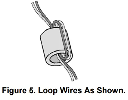
Note: Use supplied ferrite beads with digital audio controllers. Loop wires once through the supplied ferrite bead(s) as shown in Figure 5.
Audio Input Card Interconnections

Note: Refer to the Fire Alarm System Audio Input Card Installation Instructions (579-160) for information on the audio input card.
Analog Interconnections
Figure 7 is an illustration of Class A and Class B wiring from the analog audio controller to analog risers

- Leave the 4.7 K, ½ W resistors (378-056; yellow/violet/red) on the “+” to “-” terminals of unused contacts.
- All wiring is 18 AWG (0.8321 mm2 ) to 14 AWG (2.081 mm2 ), twisted shielded pair.
- Audio wiring is not to be mixed in the same jacket with other wiring (including other audio wiring).
- AC voltage rating: 10 VRMS (maximum)
- DC voltage rating: 2 VDC (maximum)
- Maximum number of analog interface cards per audio riser: 31.
- All wiring that leaves the building requires the 2081-9044 Overvoltage Protector at each entry or exit to the building.
- Maximum wire distance: 10,000 feet (3,048 m).
- Wiring must be free of all grounds.
- Set audio input card jumpers as shown in “Configuring the Audio Input Card.”
- All riser wiring is supervised and power limited
Connecting the Analog Riser to Legacy 4100
The FACP may be connected to the 4100 Legacy Audio Controller via the FACP Audio Riser and the Network input on the Legacy Controller. The FACP uses a 10VRMS Analog Audio riser. In order to interface to a legacy 4100 Audio Controller Network input, an isolation/step-down transformer must be used. This is an existing product, the Audio Isolator Assembly, PN 742-302.
The setup is slightly different from the instructions that are supplied with the module. Following are the modified installation instructions:
- Connect the incoming nominal 10 VRMS FACP Audio Riser wiring to TB1 on the audio isolator. If the installation requires IN and OUT wiring, two wires may be installed under each screw of TB1.
Note: The in and out wiring must be two separate wires. Do not loop the wire around the TB1 screws. - If there is only one audio wire pair coming into the panel, isolate and tape back the shield with high quality electrical tape.
- If the installation requires IN and OUT wiring, install as indicated in Step 1 above, connect the shields of the incoming and outgoing wires together to maintain continuity of the shield. The preferable method is to twist the shields together, solder and cover with a high quality electrical tape.
Documents / Resources
 |
Simplex 0579159 Digital Analog Audio Controllers [pdf] Instruction Manual 0579159 Digital Analog Audio Controllers, 0579159, Digital Analog Audio Controllers, Analog Audio Controllers, Audio Controllers |