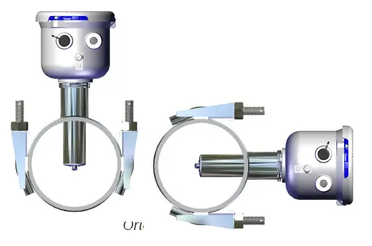
Seametrics EX90-Series Electomagnetic Insertion Flow Sensor

EEX90-SerX90-Seriesies
Electromagnetic Insertiontion Flow Sensor
GENERAL INFORMATION
- The EX90-series battery powered, insertion electromagnetic flow meter is designed for use with conductive fluids in 4”–12” pipe. The EX90’s stainless steel body allows the meter to operate in a wide range of temperatures, pressure, and corrosive or dirty environments.
- The EX90 is highly suitable for difficult applications. With no moving parts, these meters can be used in “dirty water” applications where debris would foul a mechanical meter. If the EX90 meter is used with a programmable controller, the output signal can be fed direct, with no other conditioning required.
- Rate and total units can be set via the front panel touch key pad by the user.
- Bidirectional flow is standard with totals available in forward, reverse, net, batch forward and batch reverse.
- The EX90 is battery powered with an output cable available for transmitting the pulse signal to remote devices. The EX90 can be ordered with a saddle or weld fitting designed to accommodate a wide range of pipe sizes and types while ensuring correct placement in the pipe. In addition, an optional internal data logger allows local storage of flow history.
- The EX90 is also ideal for replacement of mechanical style propeller meters.
Features
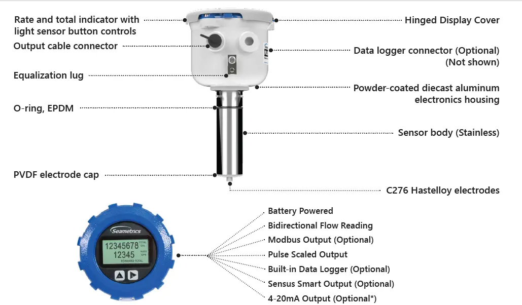
Quickly and easily change Total Volume Units, Flow Rate Units, Pulse Output Scaling, and many other settings using the two light sensor button controls on the display panel.
Flow Rate (4” – 12”)
| Nominal Pipe Size | 4” | 6” | 8” | 10” | 12” |
| Low Flow Cutoff GPM Low Flow Cutoff LPS | 19.3
1.22 |
43.11
2.72 |
77.1
4.86 |
120.5
7.6 |
173.5
10.95 |
| Min GPM Min LPS | 64.3
4.1 |
144.6
9.1 |
257
16.2 |
401.6
25.3 |
578.3
36.5 |
| Max GPM Max LPS | 578
36.5 |
1301
82.1 |
2313
145.9 |
3614
228 |
5204
328.3 |
Specifications* |
||||||
| Pipe Size |
4” to 12” |
|||||
| Materials | Sensor Body | 316 SS | ||||
| Electrodes | Hastelloy | |||||
| Housing | Powder-coated diecast aluminum | |||||
| Electrode Cap | PVDF (Kynar®) | |||||
| O-Ring | EPDM | |||||
| Temperature | Operating | 10˚ to 140˚ F (-12˚ to 60˚ C) | ||||
| Storage | -40˚ to 158˚ F (-40˚ to 70˚ C) | |||||
| Fluid Temp. | 32˚ to 200˚ F (0˚ to 93˚ C) | |||||
| Pressure | 200 psi (14 bar) | |||||
| Flow Rate | 0.5 – 4.5 m/sec (1.64 – 14.8 ft/sec) (Low flow cutoff .15 m/sec; .49 ft/sec) | |||||
| Calibration Accuracy | 0.5 – 4.5 m/s
(1.64-14.76 ft/sec) |
+/- 2% of reading | ||||
| 0.3 – 0.5 m/sec (0.98 – 1.64 ft/sec) | +/- (2% of reading + 0.25% of full scale) | |||||
| Display | Type | 128×64 dot-matrix LCD | ||||
| Digits | 5 Digit Rate | 8 Digit Total | ||||
| Units
Please Note: All meters are factory set for gallons per minute (GPM) rate and acre foot total. If other units are required, they can be set in the field. |
Rate Volume Units | Rate Time Units | Total Volume Units | |||
| Gallons Liters
Barrels (42 gallons) Cubic Feet Cubic Meters Million Gallons1 Mega Liters1 Imperial Gallons Million Imperial Gallons1 |
Second Minute Hour Day | Gallons Gallons x 10
Gallons x 100 Gallons x 1000 Million Gallons Liters Kilo Liters Mega Liters Barrels (42 gallons) Cubic Meters |
Cubic Meters x 1000 Cubic Feet
Cubic Feet x 1000 Million Cubic Feet Imperial Gallons Imperial Gallons x 1000 Million Imperial Gallons Acre Inch Acre Foot Fluid Ounce |
|||
| Bidirectional | Forward Total, Reverse Total, Net Total, Batch Forward Total, Batch Reverse Total2 | |||||
| Power | One lithium 7.2V ‘D’ size battery pack, replaceable.
DC Power available for 4-20mA output meters |
|||||
| Scaled Pulse Output | Signal | Current sinking pulse, isolated, 36 Vdc at 10 mA max | ||||
| Pulse Rates | User-scalable from 0.1 to 99,999.9 volume units/pulse. Pulse width varies with output frequency, 150 pulses/sec max | |||||
| Options | 4-20Ma Current Loop | Isolated, passive, 24Vdc, 650 Ω maximum current loop (External DC powered units only) | ||||
| Serial Communications | Isolated, asynchronous serial RS485, Modbus® RTU protocol | |||||
| Sensus Smart Output | Connects to Sensus SmartPoint | |||||
| Cable | Optional Output Cable | 20ft (6m) standard length polyurethane jacketed cable—for power and outputs.
(Lengths up to 200’ (60 m) available.) |
||||
| Conductivity | >20 microSiemens/cm | |||||
| Empty Pipe Detection | Hardware/software, conductivity-based | |||||
| Environmental | IP67 | |||||
| Modbus is a registered trademark of Schneider Electric.
* Specifications subject to change. Please consult our website for the most current data ( seametrics.com ).
Kynar is a registered trademark of Arkema, Inc. |
||||||
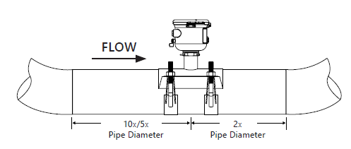
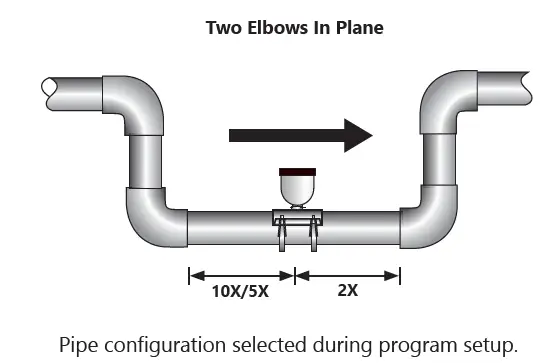
Upstream straight pipe is selected during initial setup. Upstream options are 5X or 10X the diameter and are based on the amount of straight pipe available in either new or propeller meter replacement installation. Downstream straight pipe requirement is 2X the diameter. See programming setup for details.
Dimensions
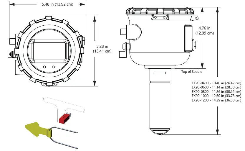
Install security clip and seal during installation if regulations require. Security seal wire threads through hole in security clip.
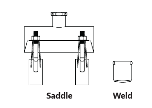
| Saddle Size | Saddle Range | Carbon or 316 SS Weld Fitting |
| 4” | 4.00”- 4.90” | 4” |
| 6” | 6.00”- 6.90” | 6” |
| 8” | 8.00” – 9.05” | 8” |
| 10” | 10.00” – 11.10” | 10” |
| 12” | 12.10” – 13.20” | 12” |
Consult factory if your OD does not match.
Install display security tab during installation if regulations require.

Install display security seal and captive screw security wire during installation if regulations require.

CAUTION: Ensure that the U-clip is installed and never remove the U-clip retainer when the pipe is under pressure. Always remove pressure from the pipe before you attempt to remove the meter. Removal under pressure may result in damage or serious injury.
INSTALLATION
Fitting Installation
EX90-Series meters require special saddles or weldo-o-lets that ensure that the flow sensor is installed to the correct depth. The fitting must be installed in the pipeline before the meter can be installed. For best results, see straight pipe and full pipe information on pages 8 and 9.
If there is not enough straight run to smooth out the turbulence caused by valves, fittings, and changes in direction, some decrease in accuracy may result. This does not mean that the flow meter’s reading is meaningless however. In some applications (control systems, valve operation, chemical addition) a repeatable reading may be more important than a highly accurate one.
Side (3 o’clock), top (12 o’clock) installations are acceptable.

Upstream straight pipe is selected during initial setup. Upstream options are 5X or 10X the diameter and are based on the amount of straight pipe available in either new or propeller meter replacement installation. Downstream straight pipe requirement is 2X the diameter. See programming setup on page 14 for details.
Chemical Injection
When any magmeter, by any manufacturer, is used in a chemical injection application (including fertigation), the chemical injection point must be placed downstream of the magmeter OR far enough upstream for complete mixing to occur before the fluid reaches the meter. When unmixed chemical or fertilizer alternates with water passing through the meter, the rapid changes in conductivity may cause sudden spikes and drops in the meter’s reading, resulting in inaccurate measurement. The magmeter will restabilize, however, with a steady flow of fluid of uniform conductivity.
Meter Installation
After the saddle or weld-o-let is installed in the pipeline, the meter can be installed in the fitting. After noting the direction of the flow arrow, press the meter into the fitting as far as it will go. Retain the meter in place by inserting the U-clip. The pin can be installed from either side. It may be necessary to rotate the probe back and forth slightly to start the pin into the slots on the probe. Slide the pin in as far as it will go.
Caution: In chemical injection applications, install chemical injection point downstream of magmeter, or far enough upstream to allow complete mixing of fluids before the meter.
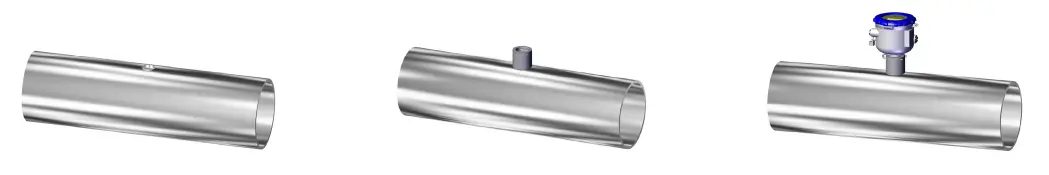
New Saddle Installation
BEFORE INSTALLING measure & record inside diameter (ID) of pipe.
- Clean the mounting surface, remove any roughness from the area and cut a 1.75” hole into pipe. Place gasket centered over pipe opening.
- Place saddle top over gasket.
- Make sure saddle top covers entire gasket.

- Place the saddle clamps under the pipe and align with the clamp guides on the saddle top.
- Place saddle plates over saddle clamp threads. Attach nuts and tighten as shown below. Torque to 75 ft-lb in cross pattern.
- Insert the EX90 sensor into the saddle fitting and secure with mounting clip or attach security clip and seals if required.

Weld-o-let Installation
BEFORE INSTALLING measure & record inside diameter (ID) of pipe.
- Clean the mounting surface, remove any roughness from the area and cut a 1.75” hole into pipe. Place gasket centered over pipe opening.
- Install weld-o-let
- Insert the EX90 sensor into the weld-o-let fitting and secure with mounting clip or attach security clip and seals if required.
Grounding
For All Installations. Although not necessarily required in every circumstance, to aid with the reduction of electrical noise, static, and induced or transient voltages, every EX90 installation will benefit by connecting the ground lug of the meter to a 5/8” x 8’ independent ground rod dedicated to the meter using at least a 10 GA ground wire.
Electronically Noisy Installations. When the EX90 is installed in an electrically noisy system, such as near a VFD etc. an independent ground rod is always recommended to help with the reduction of the electrical noise and to help protect against any large electrical spikes. In electrical noisy installations, always confirm the rest of the equipment is also well grounded. Do not connect VFD ground rods to any other equipment.

Straight Pipe Recommendations (X = diameter)
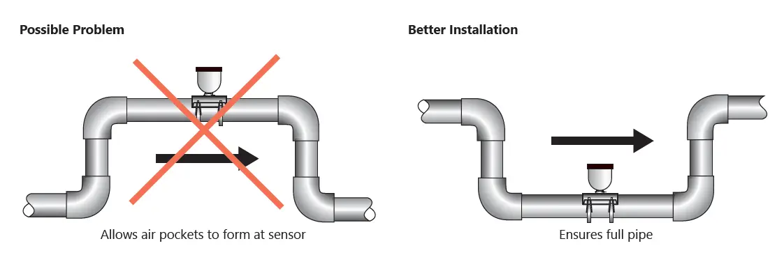
Full Pipe Recommendations


CONNECTIONS
EX90 General Cable Information
The EX90 meter has two power/output cables that can be installed. The 4-pin cable contains the wires for DC power and pulse output. The 8-pin cable contains the wires for DC power and pulse, 4-20 mA or Modbus® output options when ordered. See diagrams below for details.


Option IDs
- O ID POWER SOURCE / OUTPUT(S)
- BXX = BATTERY POWER / PULSE SCALED
- BXS = BATTERY POWER / PULSE SCALED / MODBUS®
- D1L/D2L = DC POWER / PULSE SCALED AND 4-20mA
Cable Shield. In general, the cable shield and its bare drain wire should be left unconnected at the user equipment end of the cable to minimize “ground loop” problems.
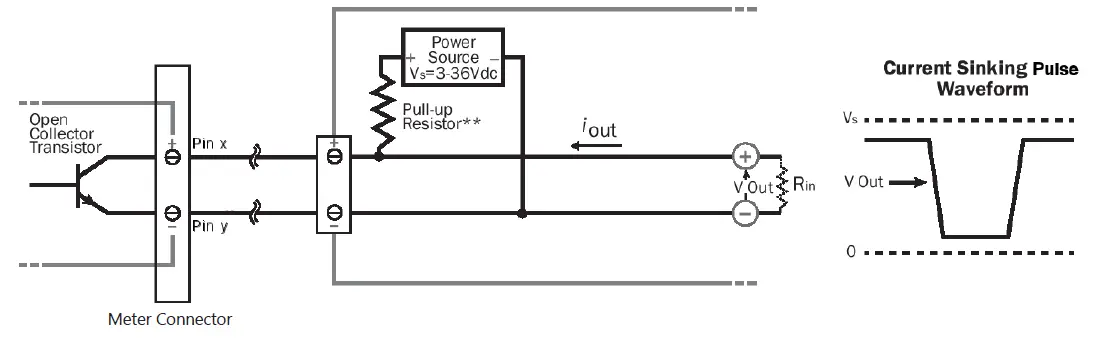
Pulse Output Configuration. A pulse output is standard on all models. Since this is an isolated output, the external equipment must include a DC power source to regenerate the pulse from the open-collector output (transistor equivalent of a contact closure). A pull-up or pull-down resistor may be needed if not included in the user equipment. Both the power source and resistor may be supplied internally in some types of control and monitoring devices. If not, as for most PLC discrete input modules, they must be added externally at the module input terminals. The pulse output rate in volume units/pulse can be set by the user via the SETP tab on the meter’s setup menus.
Because the pulse output of an EX90 meter is set by the user, care must be taken to assure the output pulses do not exceed the maximum frequency of the meter while also ensuring a reasonable resolution.
- K-factor. Remember that SETP is expressed in units totaled per output pulse (G/P if using gallons) while K-factors are expressed in pulses per gallon (P/G.) To determine K-factor from SETP, divide 1 by SETP (if SETP is expressed in gallons.)
- Conversely, 1 divided by the K-factor equals SETP
- EX90 battery powered units have a maximum output frequency of 150 Hz.
- Because all pulse outputs (SETP) are configured in (rate) units totaled per pulse, all sizes of meters can be configured with the same SETP values
- For example, if your rate is chosen as gallons per minute (GPM) the table below applies. If your rate is different, simply use your rate label in place of (GPM.) The numerical values will remain the same.
- Lower frequency output pulses (1 pulse for some particular number of gallons) can also be set.
Any output frequency can be determined by
- Rate (units/minute) ÷ SETP (units/pulse) = pulse/minute
- Hz = pulse/minute ÷ 60 seconds / minutes
| SETP | Flow Rate at 1 Hz
(GPM) |
Flow Rate at 150 Hz (GPM)
Battery Powered Meters |
| 0.1 | 6 | 900 |
| 0.2 | 12 | 1800 |
| 0.3 | 18 | 2700 |
| 0.4 | 24 | 3600 |
| 0.5 | 30 | 4500 |
| 0.6 | 36 | 5400 |
| 0.7 | 42 | 6300 |
| 0.8 | 48 | 7200 |
| 0.9 | 54 | 8100 |
| 1.0 | 60 | 9000 |
- Pulse Units. The units of measure of SETP are independently selectable and are not tied to rate or total. Upon change of the SETP unit, the pulse output may take up to 10 seconds, or the duration of one pulse (whichever is longer) to take effect.
- If Pulse Output is Inconsistent. The DAMP filter may need to be increased.
- Pulse Width Timing. The unit and value of SETP must be chosen to keep the duration between meter pulse outputs to less than 500 seconds.
- Pulse Timing in Battery Powered Units. The output pulse width in battery powered units is short and varies with pulse frequency. (See table)
| Output Pulse Width of Battery Powered Units | ||
| Output Pulse Frequency | Output Pulse Width as a Percentage of the Pulse Period
(Pulse period = 1000 milliseconds/fre- quency) |
|
| Zero to 1 Hz | Multiply the pulse period by 0.01 | = Output Pulse Width (ms) |
| >1 to 20 Hz | Multiply the pulse period by 0.05 | = Output Pulse Width (ms) |
| >20 to 100 Hz | Multiply the pulse period by 0.1 | = Output Pulse Width (ms) |
| >100 to 150 Hz | Multiply the pulse period by 0.15 | = Output Pulse Width (ms) |
Example: If frequency = 20 Hz then the pulse period = 50 milliseconds and pulse width = (.05 x 50 milliseconds) = 2.5 ms
Analog Output (4-20mA) Configuration. (Not available on battery only units.)
- Since the meter’s analog output is isolated and passive, loop power must be supplied externally as shown on next page. (In addition, an external resistor RL will be needed to convert the loop current to voltage for voltage-only input devices.)
- The meter’s loop transmitter minimum voltage drop is 6Vdc which, with wiring resistance and loop power supply voltage, will determine the maximum resistance for RL.
- The flow rates corresponding to 4 and 20mA can be set by the user via the SET 4 and SET20 tabs on the meter’s setup menus.
Note: As configured by the factory, any alarm state will force 22.8mA on the loop.
This can be changed to 3.2mA – see Technical Bulletin: iMAG4700/AG3000: Changing the 4-20mA Alarm’
Modbus® Serial Communication Configuration (factory configured)
- These connections provide a half-duplex, isolated, RS485 serial communications port using the Modbus® messaging protocol. The TXD connection is the transmitted data output from the meter and RXD is the received data input to the meter.
- See Seametric’s Modbus® Interface Description, LT-103393 (available at www.seametrics.com ) for supported Modbus® message protocol and electrical interface specifications.
- A 120-ohm termination resistor is built into the Modbus® option board but is shipped in the unused position. To engage the termination resistor, move the jumper on JP1 from position 3-4 to position 1-2.
CONFIGURATION
Pulse Output Application – Sourcing Mode (Recommended for Rin < 30kΩ)

Pulse Output Application – Sinking Mode (Recommended for Rin > 30kΩ)
Analog (4-20mA Current Loop) Output Application

- Minimum resistor value is (100 x Vs) ohms. Higher resistances maybe used depending on frequency and cable length. Longer cables and high frequencies require lower resistance.
- Resistor RL converts 4-20mA current to voltage for voltage input only devices.
OPERATION
Minimum Flow
As with any other flow sensor, there is a rate below which the EX90-Series sensor cannot read. Check the table below for the minimum flow rate detectable by the sensor for a given pipe size.
| Nominal Pipe Size | 4” | 6” | 8” | 10” | 12” |
| Low Flow Cutoff GPM Low Flow Cutoff LPS | 19.3
1.22 |
43.11
2.72 |
77.1
4.86 |
120.5
7.6 |
173.5
10.95 |
| Min GPM Min LPS | 64.3
4.1 |
144.6
9.1 |
257
16.2 |
401.6
25.3 |
578.3
36.5 |
| Max GPM Max LPS | 578
36.5 |
1301
82.1 |
2313
145.9 |
3614
228 |
5204
328.3 |
Standard Menu Options
- T UNIT
View or change TOTAL volume units - R UNIT
View or change flow RATE units - SET P
View or change pulse output scaling - DAMP
View or change # of samples for rolling average.

- SET 4
View or change flow rate corresponding to 4mA. (Externally powered units only) - SET 20
View or change flow rate corresponding to 20mA. (Externally powered units only) - EXIT
Return to HOME SCREEN or enter SUBMENU

Special SUBMENU for Further Options
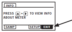
The EXIT tab in the MAIN MENU has a second function. If, instead of using the hold and tap![]() sequence to return to the HOME screen, you tap seven times, you will be redirected to a SUBMENU screen from which you can access several more options.
sequence to return to the HOME screen, you tap seven times, you will be redirected to a SUBMENU screen from which you can access several more options.
Navigation in this SUBMENU is the same as for the MAIN MENU. Whenever you wish, go to the EXIT tab in the SUBMENU and perform the hold and tap sequence to return to the MAIN MENU.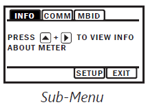
- INFO: Meter model number, serial number, and firmware version.
- COMM: Modbus® baud rate and parity.
- MBID: Modbus® address
- SAMP: Sample rate (Battery powered version only.)
- EXIT: Return to MAIN MENU or enter next submenu.

Initial Setup
INITIAL SETUP OF ID, HOLE, AND PIPE IS REQUIRED FOR THE METER TO OPERATE PROPERLY.
When you remove the meter from the box, it will prompt you to perform initial SETUP of ID, Hole and PIPE before you can proceed to other menu functions or return to the HOME screen.
SETUP Menu Functionality
The SETUP menu works slightly different than other menus inside the EX90. The black square highlighting the left most text is similar to a cursor on a computer. It lets you know where you are within the menu. Press Up 1x and the menu category will change. The categories are as follows:
- ID (Internal Diameter in inches)
- HOLE (Hole Size Cut into Pipe for Inserting Meter)
- PIPE (Piping Configuration Selection)
ID
The Internal Diameter (or I.D.) of the Pipe in which the EX90 is installed is critical to the meter’s performance. The EX90 senses a local velocity around the electrodes and uses that information to extrapolate the flow over the entire pipe section. The ID is also used ‘under the hood’ to scale many critical values such as Low Flow Cutoff, Max Flow Rate, etc. The installer should measure the ID in the most accurate way possible prior to saddle installation.
HOLE
You must change setting from the default N/A to one of the following
SMALL
New Installations will cut a 1.75” hole into the pipe. This is considered a “SMALL” hole. In this type of installation, the meter is flush to the diameter of the hole. This represents an ideal installation condition, because the cross-sectional area at the measurement point is equal to the I.D. of the pipe.
LARGE
Retrofit installations already have a hole cut into the pipe. Typically they are quite large (especially when replacing mechanical meters), although the exact size depends on the pipe size. These are considered “LARGE” holes. In this type of installation, the meter has significant room between it and the hole cut into the pipe. When water flows by the meter, it fills this extra cross sectional area while flowing past the measurement point. This means that unlike the “SMALL” hole case, the cross sectional area at the point of measurement is not equal to the I.D. of the pipe. When this menu is selected, the EX90 will compensate for this condition.
PIPE
The PIPE menu is used to compensate for altered velocity profiles in various piping configurations. When obstructions or disturbances are introduced to straight pipe (particularly upstream of the meter), the velocity profile changes shape. Since the EX90 measures a relatively small cross section of the velocity profile, large distortions of this profile can lead directly to measurement error. The pipe menu has distinct pipe configuration compensation built into the EX90 allowing you to select the closest condition to your actual pipe and allows the EX90 to operate at peak performance.
You must change setting from the default N/A to one of the following
- STRAIGHT
Straight Pipe is a relative term. For this configuration, the EX90 considers the pipe to be straight if there are 15+ diameters of straight pipe upstream from the meter and at least 2 diameters downstream from the meter from any obstruction in the pipe. - 10/2 ELB
This selection represents an install condition in which there exists a single in plane elbow 10 diameters upstream from the meter and 2 diameters downstream from the meter. - 5/2 ELB
This selection represents an install condition in which there exists a single in plane elbow 5 diameters upstream from the meter and 2 diameters downstream from the meter. - ADJ
The adjustment menu is for installers and regulating bodies. This menu allows manual adjustment of the rate (on a % of reading basis) in installations outside of the scope of this document. This menu should be used when a known reference is temporarily (or otherwise) installed into the system and adjustment can be made with high confidence and reliability.
Changing Flow Meter Settings
Home Screen and General Navigation
The HOME Screen displays flow volume, direction of the flow total and flow RATE along with status conditions such as Empty Pipe. Two buttons below the LCD display are used to access menu screens for viewing and changing meter setup parameters. 
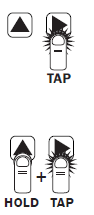
These two buttons are light sensors which can detect when a finger is covering them and operate upon release. Only three button touch actions are needed to control navigation through the menus, settings changes and back to the home screen.
HORIZONTAL SCROLLING
Tap right button to scroll horizontally through menu tabs or move horizontally within a tab dialog when applicable.
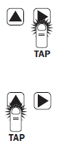
VERTICAL SCROLLING
Tap left button to change a highlighted item within a tab dialog.
SELECT/ENTER/EXIT
Hold left button while tapping right button once to enter or exit a tab dialog or to navigate between the HOME and other menu screens.

Changing Total Direction/Resetting Batch Totalizers
On the Main screen, hold ![]() 7 times to scroll through the total direction options. Release
7 times to scroll through the total direction options. Release ![]() to select a total direction.
to select a total direction.
Once BATCH FORWARD or BATCH REVERSE is selcted, tap ![]() four times to reset batch totalizer.
four times to reset batch totalizer.

To Enter the Menu System perform the hold and tap sequence. The Passcode entry screen will display. The default passcode is 000000. If a different passcode has previously been set, use the ![]() to enter that passcode. In either case, hold and tap again to move into the menu system. (If you enter the wrong passcode, hold and tap again to return to the previous screen. See page 16 for information on how to change a passcode.)
to enter that passcode. In either case, hold and tap again to move into the menu system. (If you enter the wrong passcode, hold and tap again to return to the previous screen. See page 16 for information on how to change a passcode.)
Making Selections
Once in the Menu System, move from tab to tab by tapping the right button. (See the next page for details on the various available tabs.)
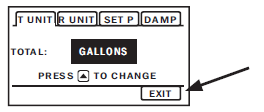
Select the Parameter. In the screen for the highlighted tab you will see the current parameter value for that tab. Tapping the right button, move to the tab for the parameter you want to change.
In this example, the first line indicates that the current unit for the TOTAL is GALLONS. The next two lines tell you what to do next.


If you would like to change the TOTAL units, just perform the hold and tap sequence to bring up a screen to change the setting.

Scroll Through Setting. Select the new setting by scrolling through a list of selections by tapping the left button to find a different TOTAL unit.

Accept Changes. To accept any changes you have made, perform the hold and tap sequence.
When Finished Making Changes. When you are finished making changes, move to the EXIT tab using the right button.
To return to the HOME screen, perform the hold and tap sequence.
Programming Passcode and Tamper Prevention
To prevent tampering or changes to the program, after initial set-up, either enter a security pass-code, or remove the display lid and place a security tab over one of the arrows before installing the housing security seal.
Placing a security tab over either display button will prevent additional changes to the program, while allowing someone to wake the display from sleep mode. Placement over the right button will also allow scrolling through the flow direction feature. Placement over the left button will prevent changes to the flow direction. In either position, non-resettable totals will not be affected.
The EX90 has a passcode system for restricting access to the menus. The EX90 comes from the factory with the passcode set to 000000. When a user attempts to enter the menu system (see details on page 14), the passcode entry screen will be displayed.

The default passcode is 000000. If a different passcode has previously been set, then the user must enter that passcode at this time. After entering the passcode, or leaving it at 000000 if using the default passcode, the user does the hold and tap sequence to move into the menu system.
To change the passcode, you must use the THIRD MENU screen. Access the THIRD MENU screen as follows
Enter the main menu system, as described above
On the main menu, tab over to the EXIT tab and tap the up arrow five times. A SUBMENU screen will display
- On the SUBMENU screen tab over to the EXIT tab and tap the up arrow five times. The THIRD MENU screen will display.

- To set the code, hold and tap SETCD and then use the
 to enter the new code.
 - Hold and tap again to return to the THIRD MENU screen.
- Tab to EXIT, and then hold and tap to return to the SUBMENU.
To change the number of decimal places in the total
- To set the decimal point, hold and tap on SETD and then use the
 to move the decimal point.
 - Hold and tap again to return to the THIRD MENU screen.
- Tab to EXIT, and then hold and tap to return to the SUBMENU.
Power Indicators
- A power indicator is displayed in the lower left of the main display window.
- Any meter powered from an external power source will display a power plug icon when running on external power.
- If the connection to external power is lost, the meter will switch to the backup battery and the power icon will switch to a battery symbol.
- OK on the battery indicator means battery voltage is above 6.4 volts.
- LO on the battery indicator means the battery is low and should be replaced soon.

PDAMP
PDAMP is used to view or change the number of samples for rolling average of pulse output
TEST
TEST allows the user to initiate a fully functional, artificial flow rate for the purpose of testing other connected equipment. When TEST is applied, all features of the meter will function at the stated flow rate (in gallons per second).
For TEST to function, the meter must be filled (not EMPTY PIPE).
To enter a value into the TEST feature, navigate to the TEST tab and enter a flow rate value in the VAL screen (in gallons per second only,) then ![]() to the VAL box and
to the VAL box and ![]() to the ON screen. This will initiate the TEST feature. The next
to the ON screen. This will initiate the TEST feature. The next![]() would bring you to the OFF screen, but you can ‘hold and tap’ the arrows to return you to the sub menu while the feature operates.
would bring you to the OFF screen, but you can ‘hold and tap’ the arrows to return you to the sub menu while the feature operates.
After use, the TEST feature must be turned OFF. If the TEST feature is not turned OFF, the stated static flow rate (in gallons per second) will be shown any time the meter is full or in a flowing condition. Flow values recorded by the meter while the TEST feature is operating are permanently recorded in the displayed TOTAL. It may be useful to note that these values are only written to permanent memory every 15 minutes and cycling all power within this 15 minute time frame will return the meter to its previous total.
Battery Powered Units
- To ‘wake up’ a battery powered meter, you may need to hold the up arrow for 5 seconds and release.
- The EX90 meter comes configured with a 7.2V ‘D’ size lithium battery pack. In this configuration, the only option/output is the scaled pulse output which comes standard. Be sure to set your SETP value such that the meter will function properly over the flow range in your application (see page 11 for details). The sample rate of the meter is user selectable through the SAMP tab in the meter’s sub-menu. Sample periods of 1/5, 1/3, 1, 3, 5, 15, 30, and 60 seconds can be selected.
- (A sample period of 15 seconds – 5.5 year battery life – is the default.)
- Larger sample periods will yield longer battery life but slower response time. Care must be taken to select a sample period that is suitable for your application. See the table below for the expected battery life as a function of sample period.
DAMP/Filtering
The DAMP Filter allows multiple readings to be averaged over time, thus reducing the meters sensitivity to minor changes in flow rate. The DAMP Filter is extremely useful for situations where the flow is not perfectly steady (pulsating flows, turbulent flows, etc.)
The DAMP Filter works differently depending on the SAMP selection
SAMP < 1 second
When the SAMP setting is less than 1 second, the DAMP filter is defined on a “per second” basis. The DAMP filter always utilizes at least 1 second of data for its filter. Then, it adds however many seconds you’ve selected in the DAMP menu setting to that 1 second of data. For instance, if you set the DAMP menu to 7, your EX90 meter will utilize 7+1=8 seconds of data within the filter. This means that the filter will average readings for 8 seconds prior to displaying a reading. After the first reading is displayed, the filter kicks out the oldest 1 second of data, adds the newest 1 second of data, recomputes the average flow rate, and displays it to the screen/output. In this way, it is considered a “running average”.
SAMP > 1 second
When the SAMP menu is set to a number greater than 1 second, the DAMP menu is defined on a “per reading” basis. Again, the DAMP filter must always use at least 1 reading to generate a flow rate, so the filter will add 1 to your selection. For instance, if SAMP is set to 15, and DAMP is set to 7, the DAMP filter will utilize 7+1=8 readings worth of data for the filter. This means that the filter will average 8 readings for the display.
Battery Life/Sample Period
| Sensor sample period(s) (Seconds) | Expected battery life* |
| 1/5 (0.2) | 4.5 Months |
| 1/3 (0.33) | 7 Months |
| 1 | 1.5 years |
| 3 | 3.25 years |
| 5 | 4 years |
| 15 | 5.5 years |
| 30 | 6 years |
| 60 | 6.25 years |
*Based on 85% battery capacity at room temperature.
TROUBLESHOOTING & ERROR MESSAGES
Troubleshooting
| Problem | Probable Causes | Things to try… |
| Blank Display | Battery has not been plugged in Dead battery |
|
| Flow rate reading fluctuates excessively when flow is unchanging | Excessively turbulent or unsteady flow due to partially closed valves or other flow obstructions | Eliminate or minimize causes of flow disturbances or increase meter damping |
| Pipe not full | Provide back pressure or other means to ensure pipe is filled | |
| Pulsing flow due to combining multiple upstream flow sources | Move connection point further upstream | |
| Insufficient mixing of upstream chemicals | Move chemical injection downstream from meter | |
| Low fluid conductivity < 20 µS/cm | Replace with different type of meter | |
Noisy electrical environment
|
|
|
| Flow Rate appears correct but pulse/ frequency output is low, erratic or absent |
|
|
| Flow Rate appears correct but pulse/frequency output is erratic and/or too high | Electrical noise sources interfering with pulse frequency signal | Isolate, remove or reduce noise sources. Move meter control cable away from noise sources. |
| Wrong type of cable | Use only twisted pair cable and ensure both signal wires are on same twisted pair | |
| Grounding problem | Improve or try different grounding method | |
| Flow rate steadily reads
zero when there is flow |
|
|
| Flow rate intermittently
drops when there is flow |
Air in the pipe | Reposition meter for full pipe |
| Jumpy reading |
|
|
Error Messages
Under certain conditions an error message may be displayed.
| Message | Description | Notes |
| INIT | Initialization is occurring during power up. | |
| EMPTY PIPE | Fluid is not detected between the sensing electrodes. | |
| LO in battery icon | Battery is getting low, replace soon. Meter still functions. | Above 6.4V, OK appears in icon |
| BATT END | Battery is very low (approx. 6.1V). Totalizer stops updating. | |
| COIL FAIL | Coil current too high or too low (short or open). | |
| COMM FAIL | Communication between transmitter and sensor board fails. | |
| OVER RANGE | Rate exceeds number of digits that can be displayed. Adjust units. | |
| SET ID | Pipe ID has not been set. | |
| SET HOLE | Installation hole type (small, large) has not been set. | |
| SET PIPE | Pipe setting has not been selected. | |
| INIT FAIL | Initialization has failed. Ribbon cable plugged in AFTER power, or there is no communication between transmitter & sensor board. | Try power reset |
SEAMETRICS LIMITED WARRANTY
The limited warranty set forth below is given by Seametrics, with respect to Seametrics brand products purchased in the United States of America.
Seametrics warrants that products manufactured by Seametrics, when delivered to you in new condition in their original containers and properly installed, shall be free from defects in material and workmanship. Seametrics products are warranted against defects for a minimum period of two (2) years from date of installation, unless otherwise specified, with proof of install date.
If no proof of install date can be provided, warranty period will be two (2) years from date of shipment from Seametrics, as defined on Seametrics’ invoice. Seametrics’ obligation under this warranty shall be limited to replacing or repairing the part or parts, or, at Seametrics’ option, the products, which prove defective in material or workmanship. The following are the terms of Seametrics’ limited warranty
- Buyer must give Seametrics prompt notice of any defect or failure and satisfactory proof thereof.
- Any defective part or parts must be returned to Seametrics’ factory or to an authorized service center for inspection.
- Buyer will prepay all freight charges to return any products to Seametrics’ factory, or another repair facility. as designated by Seametrics.
- Defective products, or parts thereof, which are returned to Seametrics and proved to be defective upon inspection, will be repaired to factory specifications.
- Seametrics will deliver repaired products or replacements for defective products to the buyer (ground freight prepaid) to the destination provided in the original order.
- Products returned to Seametrics for which Seametrics provides replacement under this warranty shall become the property of Seametrics.
- This limited warranty covers all defects encountered in normal use of Seametrics products, and does not apply to the following cases
- Loss of or damage to Seametrics product due to abuse, mishandling, or improper packaging by buyer
- Failure to follow operating, maintenance, or environmental instructions prescribed in Seametrics’ instruction manual
- Products not used for their intended purpose
- Alterations to the product, purposeful or accidental
- Electrical current fluctuations
- Corrosion due to aggressive materials not approved for your specific product
- Mishandling, or misapplication of Seametrics products
- Products or parts that are typically consumed during normal operation
- Use of parts or supplies (other than those sold by Seametrics) which cause damage to the products, or cause abnormally frequent service calls or service problems
- A new warranty period will be established for repaired products, or products replaced during the original warranty period.
- In the event that equipment is altered or repaired by the buyer without prior written approval by Seametrics, all warranties are void. Damage caused by equipment or accessories not manufactured by Seametrics may void the product’s warranty.
- SOFTWARE: The Seller grants the user a non-exclusive license to use Seametrics’ software, according to the following limitations and conditions:
- The user may install the software on one or more desktop or laptop computers.
- All title and intellectual rights to the software are owned by Seametrics.
- No copies may be made or distributed except as described above.
- The user may not modify or reverse-engineer the software.
THE FOREGOING WARRANTY IS IN LIEU OF ALL OTHER WARRANTIES, WHETHER ORAL, WRITTEN, EXPRESSED, IMPLIED OR STATUTORY. NO IMPLIED WARRANTY, INCLUDING ANY IMPLIED WARRANTY OF MERCHANTABILITY OR FITNESS FOR A PARTICULAR PURPOSE, APPLIED TO THE PRODUCTS AFTER THE APPLICABLE PERIOD OF THE EXPRESS LIMITED WARRANTY STATED ABOVE, AND NO OTHER EXPRESS WARRANTY OR GUARANTY, EXCEPT AS MENTIONED ABOVE, GIVEN BY ANY PERSON OR ENTITY WITH RESPECT TO THE PRODUCTS, SHALL BIND SEAMETRICS. SEAMETRICS SHALL NOT BE LIABLE FOR LOSS OF REVENUES, OR PROFITS, OR INCONVENIENCES, EXPENSE FOR SUBSTITUTE EQUIPMENT OR SERVICE, STORAGE CHARGES, LOSS OF DATA, OR ANY OTHER SPECIAL, INCIDENTAL, OR CONSEQUENTIAL DAMAGE CAUSED BY THE USE OR MISUSE OF, OR INABILITY TO USE THE PRODUCTS, REGARDLESS OF THE LEGAL THEORY ON WHICH THE CLAIM IS BASED, AND EVEN IF SEAMETRICS HAS BEEN ADVISED OF THE POSSIBILITY OF SUCH DAMAGES. IN NO EVENT SHALL RECOVERY OF ANY KIND AGAINST SEAMETRICS BE GREATER IN AMOUNT THAN THE PURCHASE PRICE OF THE PRODUCT SOLD BY SEAMETRICS AND CAUSING THE ALLEGED DAMAGE. WITHOUT LIMITING THE FOREGOING, YOU ASSUME ALL RISK OF LIABILITY FOR LOSS, DAMAGE, OR INJURY TO YOU AND YOUR PROPERTY AND TO OTHERS AND THEIR PROPERTY ARISING OUT OF USE OR MISUSE OF, OR INABILITY TO USE THE PRODUCTS NOT CAUSED DIRECTLY BY THE NEGLIGENCE OF SEAMETRICS.
SOME STATES DO NOT ALLOW LIMITATIONS ON THE DURATION OF AN IMPLIED WARRANTY, SO THE ABOVE LIMITATIONS MAY NOT APPLY TO YOU. SIMILARLY, SOME STATES DO NOT ALLOW THE EXCLUSION OR LIMITATIONS OF CONSEQUENTIAL DAMAGE, SO THE ABOVE LIMITATION OR EXCLUSION MAY NOT APPLY TO YOU. THIS LIMITED WARRANTY GIVES YOU SPECIFIC LEGAL RIGHTS; HOWEVER, YOU MAY ALSO HAVE OTHER RIGHTS WHICH MAY VARY FROM STATE TO STATE.
- Seametrics
- 19026 72nd Avenue South
- Kent, Washington 98032
- USA
- (P) 253.872.0284
- (F) 253.872.0285
- 1.800.975.8153
- seametrics.com
Documents / Resources
 |
Seametrics EX90-Series Electomagnetic Insertion Flow Sensor [pdf] Instruction Manual EX90-Series Electomagnetic Insertion Flow Sensor, EX90-Series, Electomagnetic Insertion Flow Sensor, Insertion Flow Sensor, Flow Sensor, Sensor |


