ROLLOMATIC Version 1 Concentricity Pro Instructions

The Rollomatic “V-Block” Concentricity Pro is capable of measuring the run-out on cylindrical components below .00004″ (1 micron) and can ideally be used in the cutting tool, punching, bar-turning, semi-conductor, automotive and aerospace industries.
The combination of a special rotary drive (patent pending) together with the traditional “zero-error” carbide V-block system offers concentricity gaging for use on comparators or as a free-standing unit with dial indicators or laser scanners.
VER. JANUARY 2002
![]()
ROLLOMATIC SA
Z.I. Prés Bugnons, CH-2525 Le Landeron SWITZERLAND
Phone +41 32-752-1700 / Fax +41 32-752-1717 / E-mail info@rollomatic.ch
THE PERFECT CONCENTRICITY GAGING SYSTEM
The Rollomatic Concentricity Pro represents a totally new approach to concentricity gaging and provides guaranteed improvements in accuracy and efficiency. This quality inspection device is available in 3 versions:
Version 1
As a stand-alone unit for comparators and contour projectors
Version 2
Mounted on a surface plate with precision dial indicator and articulated arm
Version 3
Mounted on a surface plate with a high-accuracy laser scanner to measure diameter and concentricity (for measuring “odd – flutes” on cutting tools, a PC program is available – supplied by Rollomatic)

CHAPTER 0. INTRODUCTION
This concentricity measuring instrument was designed to complement the Rollomatic family of products and promote Rollomatic’s image: precision & concentricity in grinding tools.
Several features of the “Concentricity Pro” are being patented.
The “Concentricity Pro” is available as a separate instrument to be mounted on a profile projector, as a stand alone concentricity measuring station or with a steel base and a laser scanner.
CHAPTER 1. CALIBRATION
The Concentricity Pro has been calibrated before shipment. If it becomes necessary to calibrate it, follow the procedure described here:

A. Place the Ø 12.07 mm calibration pin (which comes with the concentricity pro) under the silver colored stopper plate as shown on photo 1.1A, and lock it in place tightly with the stopper lock.
B. Space the “V block pair unit” approximately 25mm (1″) as shown on photo 1.1A and tighten the “V” lock (photo 1.1B).
C. Place the Ø 5 mm blank supplied with the concentricity pro on the “V” guides. Bring the tool rotation arm onto the tool shank. Loosen the screw of the silver colored stopper plate (photo 1.1C) and bring the “precision stopper rod” down until it touches the 5 mm blank. Tighten the screw.
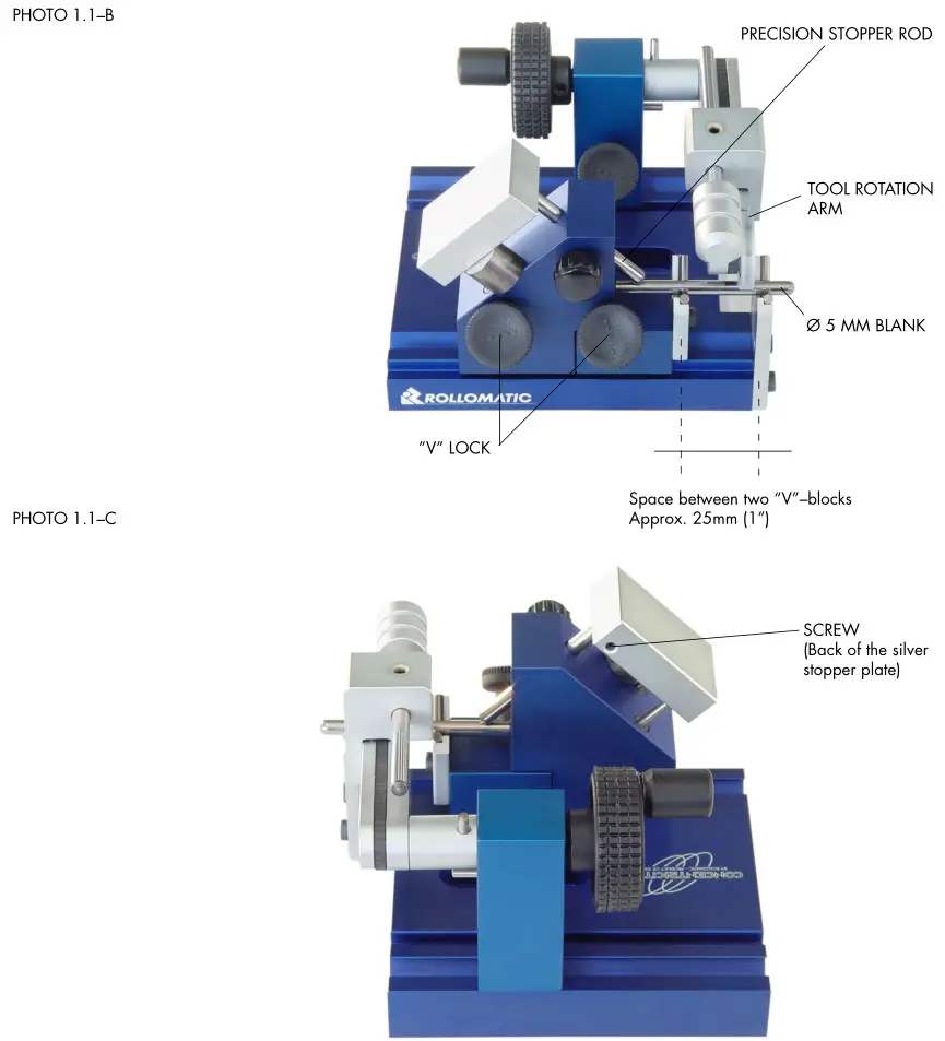
The stopper rod has a ball shape end. The calibration procedure ensures that one point of the ball will touch the exact center of the blank to be measured (if the blank is not cut straight, rotating it will create an axial movement).
NOTE: In case of wear-off of the precision stopper rod rotate the rod.
CHAPTER 2. USING THE CONCENTRICITY PRO
Before using the Concentricity Pro, clean well the tool to be measured.
A. Place the shank of the tool to be measured under the silver colored stopper plate as shown on the photo 2.1A. Slightly press the stopper plate and tighten the stopper lock.

B. Space the “V”block pair unit as desired (they should be spaced as much as possible) and tighten the “V” lock. Put the tool to be measured on the “V” blocks and bring the tool rotation arm onto the tool shank approximately at equal distance from both “V” blocks.
C. Rotate the handle to rotate the tool. Because the tool rotation arm is slightly inclined, turning the handle clockwise will push the tool against the stopper for very accurate tool rotation.
CHAPTER 3. CHANGING THE “V” GUIDES
A. Move the “main” block to the very right, so that the pins of the block reach beyond the guide rail.

B. Fix the main block in position by tightening the “V” lock. Attach the front “V” block by means of the pins, which ensure a perfect positionning of the “V” block. Fix the “V” block with 2 allan screws (see PHOTO 3.1B).

··· NOTE:
The main block must be set back a few millimeters so that the front “V” block rests correctly on the surface plate.
C. Position the main block at the desired distance, attach the back “V” block and tighten the “V” lock. The “V” block is attached to the main block via the pins.

Fix the back “V” block in position by means of an allan screw.
The “V” blocks are now mounted.


Documents / Resources
 |
ROLLOMATIC Version 1 Concentricity Pro [pdf] Instructions Version 1, Version 2, Version 3, Version 1 Concentricity Pro, Version 1, Concentricity Pro, Pro |