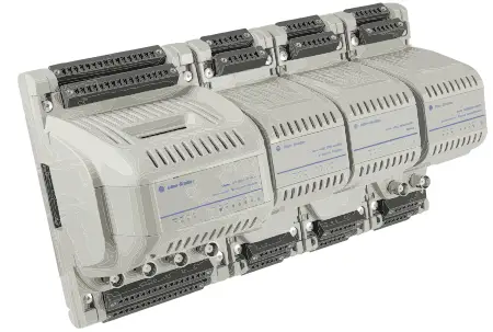
Rockwell Automation Dynamix 1444 Series Monitoring System
Specifications
Technical Data – Dynamix 1444 Series Monitoring System
- Catalog Numbers: 1444-DYN04-01RA, 1444-TSCX02-02RB, 1444-RELX00-04RB, 1444-AOFX00-04RB, 1444-TB-A, 1444-TB-B
- Enclosure type rating: IP20
- Temperature code: T3C
- Voltage range, input: 85-264V AC
- Conformal Coating
- Operating humidity: 5-95% non-condensing
- Vibration resistance: 2g @ 10-500 Hz
- Shock resistance: 15g
- Electromagnetic compatibility: IEC 61000-6-4
- Electrostatic discharge immunity: 6kV contact discharges, 8kV air discharges
Product Usage Instructions
Installation and Setup
- Identify the modules needed for your application based on the machinery being monitored.
- Ensure you have the required terminal bases and interconnect cables for installation.
- Follow the installation instructions provided in the user manual for each module.
- Create a local bus by connecting the modules using the terminal bases and cables.
Operation
- Power on the Dynamix 1444 Series Monitoring System.
- Monitor the machinery condition through the connected modules.
- Refer to the user manual for specific information on interpreting data and alarms.
- Maintain regular checks and calibrations as recommended by the manufacturer.
Maintenance
- Periodically inspect the modules and terminal bases for any signs of damage or wear.
- Clean the modules and connections to ensure proper functioning.
- Follow any specific maintenance procedures outlined in the user manual for each module.
Dynamix 1444 Series Monitoring System Specifications
- Catalog Numbers 1444-DYN04-01RA, 1444-TSCX02-02RB, 1444-RELX00-04RB, 1444-AOFX00-04RB, 1444-TB-A, 1444-TB-B
| Topic | Page |
| Summary of Changes | 2 |
| Dynamix 1444 Series Modules Common Information | 3 |
| Dynamic Measurement Module | 5 |
| Tachometer Signal Conditioner Expansion Module | 13 |
| Relay Expansion Module | 15 |
| Analog Output Expansion Module | 17 |
| Terminal Bases | 18 |
| Software, Connectors, and Cables | 19 |
| Additional Resources | 21 |
- The Dynamix™ 1444 series of intelligent I/O modules provides an integrated, distributed solution to monitor the condition of
critical machinery. The system can monitor and protect motors, pumps, fans, gearboxes, steam and gas turbines, high-speed compressors, and other machines that rotate or reciprocate. - The Dynamix system can measure dynamic signals such as vibration, strain or pressure, and position measures, such as thrust, differential expansion, or rod position. Measurements are made in real time to protect industrial machinery from possible failure, and then processed to calculate critical fault parameters that are used to assess the current and predicted health of the machines.
- Configuration and management of the Dynamix system is accomplished through a Logix controller that is linked via an EtherNet/IP™ network. As part of the Integrated Architecture® system, other components such as controllers, visualization products, other input/output products, and others are easily applied to build a solution to the specific needs of an application.
Summary of Changes
This publication contains the following new or updated information. This list includes substantive updates only and is not intended to reflect all changes.
Dynamix 1444 Series Modules
Common Information
The Dynamix modules monitor the condition of industrial machinery that rotates and reciprocates. Use the modules in combination as is necessary to the application.
| Type | Module | Cat. No. | Page |
|
Module |
Dynamic measurement (main) module | 1444-DYN04-01RA | 5 |
| Tachometer signal conditioner (speed) expansion module | 1444-TSCX02-02RB | 13 | |
| Relay expansion module | 1444-RELX00-04RB | 15 | |
| Analog output (4…20 mA) expansion module | 1444-AOFX00-04RB | 17 | |
| Terminal base(1) | Dynamic measurement module terminal base | 1444-TB-A |
18 |
| Expansion modules terminal base | 1444-TB-B |
- To use and install each module and to create a local bus, a terminal base and the corresponding interconnect cable are required. For more information, see page 18.
All Dynamix modules and terminal bases have the following specifications and certifications in common. For specifications specific to each module and terminal base, see the corresponding sections that are listed in the previous table.
Common Technical Specifications – 1444 Series
| Attribute | 1444-DYN04-01RA, 1444-TSCX02-02RB, 1444-RELX00-04RB,
1444-AOFX00-04RB, 1444-TB-A, 1444-TB-B |
| Enclosure type rating | None (open-style) |
| Temperature code | T4 |
| Voltage range, input | North American: 18…32V, max 8 A, Limited Voltage Source ATEX/IECEx: 18…32V, max 8 A, SELV/PELV Source |
|
Conformal Coating |
All printed circuit boards are conformally coated in accordance with IPC-A-610C and in compliance with:
• IPC-CC-830 B • UL508 |
Common Environmental Specifications – 1444 Series
|
Attribute |
1444-DYN04-01RA,
1444-TSCX02-02RB, 1444-RELX00-04RB, 1444-AOFX00-04RB, 1444-TB-A, 1444-TB-B |
| Temperature, operating
IEC 60068-2-1 (Test Ad, Operating Cold), IEC 60068-2-2 (Test Bd, Operating Dry Heat), IEC 60068-2-14 (Test Nb, Operating Thermal Shock): |
-25…+70 °C (-13…+158 °F) |
| Temperature, surrounding air, max | 70 °C (158 °F) |
| Temperature, nonoperating
IEC 60068-2-1 (Test Ab, Unpackaged nonoperating Cold), IEC 60068-2-2 (Test Bb, Unpackaged nonoperating Dry Heat), IEC 60068-2-14 (Test Na, Unpackaged nonoperating Thermal Shock): |
-40…+85 °C (-40…+185 °F) |
| Relative humidity
IEC 60068-2-30 (Test dB, Unpackaged Damp Heat): |
5…95% noncondensing |
| Vibration
Per IEC 600068-2-6 (Test Fc, Operating): |
2 g @ 10…500 Hz |
| Shock, operating
IEC 60068-2-27 (Test Ea, Unpackaged Shock): |
15 g |
| Shock, nonoperating
IEC 60068-2-27 (Test Ea, Unpackaged Shock): |
30 g |
| Emissions | IEC 61000-6-4 |
| ESD immunity IEC 61000-4-2: | 6 kV contact discharges 8 kV air discharges |
Common Certifications – 1444 Series
| Certification(1) | 1444-DYN04-01RA,
1444-RELX00-04RB |
1444-TSCX02-02RB,
1444-AOFX00-04RB, 1444-TB-A, 1444-TB-B |
|
c-UL-us |
UL Listed Industrial Control Equipment, which is certified for US and Canada. See UL File E65584.
UL Listed for Class I, Division 2 Group A,B,C,D Hazardous Locations, which are certified for U.S. and Canada. See UL File E194810. |
|
|
CE |
European Union 2004/108/EC EMC Directive, compliant with:
• EN 61326-1; Meas./Control/Lab, Industrial Requirements • EN 61000-6-2; Industrial Immunity • EN 61000-6-4; Industrial Emissions • EN 61131-2; Programmable Controllers (Clause 8, Zone A & B) |
|
| European Union 2006/95/EC LVD, compliant with:
EN 61131-2; Programmable Controllers (Clause 11) |
– |
|
| RCM | EN 61000-6-4; Industrial Emissions | |
|
ATEX and UKEX |
UK Statutory Instrument 2016 No. 1107 and European Union 2014/34/EU ATEX Directive, compliant with: | |
| • EN IEC 60079-0:2018; General
requirements • CENELEC EN IEC 60079-7:2015+A1:2018, Explosive Atmospheres, Protection “e” • CENELEC EN IEC 60079-15:2019, Potentially Explosive Atmospheres, Protection “n” • Ex ec nC IIC T4 Gc • DEMKO 14 ATEX 1365X and UL22UKEX2750X |
• EN IEC 60079-0:2018;
General requirements • CENELEC EN IEC 60079-7:2015+A1:2018, Explosive Atmospheres, Protection “e” • Ex ec IIC T4 Gc • DEMKO 14 ATEX 1365X and UL22UKEX2750X |
|
|
IECEx |
IECEx systems compliant with: | |
| • IEC 60079-0:2018; General requirements
• IEC 60079-7:2015+A1:2018, Explosive Atmospheres, Protection “e” • IEC 60079-15:2019, Potentially Explosive Atmospheres, Protection “n” • Ex ec nC IIC T4 Gc • IECEx UL 14.0010X |
• IEC 60079-0:2018;
General requirements • IEC 60079-7:2015+A1:2018, Explosive Atmospheres, Protection “e” • Ex ec IIC T4 Gc • IECEx UL 14.0010X |
|
| KC | Korean Registration of Broadcasting and Communications Equipment, compliant with:
Article 58-2 of the Radio Waves Act, Clause 3 |
|
|
CCC |
CNCA-C23-01
CNCA-C23-01 CCC Implementation Rule Explosion-Proof Electrical Products CCC 2020122309113798 |
|
|
UKCA |
2016 No. 1091 – Electromagnetic Compatibility Regulations
2016 No. 1107 – Equipment and Protective Systems Intended for Use in Potentially Explosive Atmospheres Regulations 2012 No. 3032 – Restriction of the Use of Certain Hazardous Substances in Electrical and Electronic Equipment Regulations |
|
- See the Product Certification link at rok.auto/certifications for Declarations of Conformity, Certificates, and other certification details.
API-670 Compliance
The Dynamix system is designed in accordance with the relevant sections of the 5th Edition of the American Petroleum Institutes (API) standard 670,(a) ‘Machinery Protection Systems’.
- System compliance is based on the components that are provided, the optional elements of the standard that you require, and the configuration of the installed system.
Removal and Insertion Under Power
All Dynamix modules can be removed and replaced while power is applied to its terminal base(a)(b).
WARNING:
- If you insert or remove the module while backplane power is on, an electric arc can occur. This arc could cause an explosion in hazardous location installations. Be sure that power is removed or the area is nonhazardous before proceeding.
- If you connect or disconnect wiring while the field-side power is on, an electric arc can occur. This arc could cause an explosion in hazardous location installations. Be sure that power is removed or the area is nonhazardous before proceeding.
DIN Rail Requirements
- Mount the terminal bases on a 35 x 7.5 mm (1.38 x 0.30 in.) DIN rail according to EN 50022, BS 5584, or DIN 46277-6.
- Dynamix modules do not connect a ground to the DIN rail, therefore you can use both uncoated or coated DIN rail.
Controller Independence
- While the Dynamix system is dependent on a Logix controller for the initial configuration. If communication with the controller is lost, the system continues to measure signals, evaluate alarm conditions, actuate relays, and send data(c).
- Also, the dynamic measurement module maintains the initial configuration in nonvolatile memory. After any subsequent power cycle, the module loads the configuration from the nonvolatile memory and the functions of the system resume.
- If a removed module includes an energized relay, the relay goes to its de-energized state.
- If Ethernet is daisy chained, one module to the next, and DLR is not used, removal of a main module causes the loss of Ethernet communication to all ‘downstream’ main modules.
- Only the host controller can change the configuration of a module. Other processors, such as personal computers, DCS computers, or other controllers, can query the module for data.
Dynamic Measurement Module
1444-DYN04-01RA
 The dynamic measurement module has four channels and uses general-purpose monitoring. The module is used to protect and monitor the condition of industrial machinery. The module supports measurements of dynamic inputs such as vibration and pressure, and static inputs such as thrust, eccentricity, and rod drop.
The module can be used to monitor these conditions:
- Shaft vibration
- Casing vibration
- Pedestal vibration
- Shaft and rod position
- Casing expansion
- Other critical dynamic and position measurements on machines that rotate or reciprocate
To achieve this amount of adaptability, this module contains flexible firmware and a powerful multi-processor hardware platform.
- The dynamic measurement module is designed for integration with Logix 5000® controllers that are connected across an industrial Ethernet network. This design makes the Dynamix system a synergistic member of larger total facility control and information management systems.
Technical Specifications – 1444-DYN04-01RA
| Attribute | 1444-DYN04-01RA |
Channel Inputs (4)
|
Sensor types |
ICP accelerometers (CCS) Dynamic pressure transducers
Dual sensors (acceleration + temperature) Eddy current probe systems (-24V DC) Self-powered sensors Voltage signals |
| Transducer positive power | Constant current: 4 mA @ 24V Voltage regulated: 24V/25 mA |
| Transducer negative power | Voltage regulated: -24V/25 mA |
| Voltage range | ± 24V DC |
| Isolation | Non-isolated, single-ended analog inputs. Sensor signal returns must be isolated from the ground |
| Impedance | >100 kΩ |
| Protection | Reverse polarity |
|
Transducer fault detection |
Bias level high / low limits |
| Current threshold level monitoring, which is implemented in hardware for
-24V supplied sensors. Provides the fastest fault detection possible with excellent reliability. |
| Attribute | 1444-DYN04-01RA |
| Conversion | 24 bit |
| Accuracy | ±0.1% (typical)
See the Dynamix 1444 Series Monitoring System User Manual, publication 1444-UM001 for more information. |
| Resolution | 3 µV (theoretical) |
| Dynamic range | 80 dBfs (0.01% FS), 90 dBfs typical |
| Sample rate | 2 Channels: 93 kS/s
4 Channels: 47 kS/s |
Tachometer Inputs (2)
| Terminal inputs | TTL class with internal pull-up resistor (5V DC) |
| Local bus inputs | Opto-isolated TTL input for signal and TX status |
| Detection threshold | Fixed (-2.5V DC) |
| Transducer status | Only local bus inputs |
| Protection | Reverse polarity |
Digital Inputs (2)
| Connection | Terminal pins |
| Type | TTL class |
| Power | 32V DC, 15 mA max per output |
| Isolation | Non-isolated |
|
Application |
Trip inhibit/bypass Alarm/relay reset
Alarm SPM/gate control 0, 1 Tachometer 0, 1 status |
Digital Outputs (2)
| Connection | Terminal pins |
| Type | Opto-isolated open-collector |
| Power | 32V DC, 15 mA max per output |
|
Application |
Module status Tachometer 0, 1 TTL
Tachometer 0, 1 status Replicate digital input 0, 1 Transducer 0…3 Status Voted alarm 0…12 status |
Buffered Outputs (4)
|
BNC |
For temporary connection to instruments, such as portable data collectors or analysis systems over distances ≤10 m (32 ft).
Resistance: 100 Ω Protection: ESD/EFT |
|
Terminal Pins |
For permanent connections to instruments or over distances that are 10 m…100 m (32 ft…328 ft).
Resistance: 100 Ω Protection: ESD/EFT, Surge |
| Power | To reduce the power requirement and heat load when not required, you can enable or disable with a local switch.
Buffered outputs operating power: ≈0.8 W |
|
Notes |
• All outputs are single-ended and have no isolation.
• Buffered output is not representative of input when no load (sensor) is connected to the associated measurement channel. • Confirm that the connected instrumentation does not provide power, such as if to power an accelerometer, to the buffer output. |
| Attribute | 1444-DYN04-01RA |
Relay (1)
| Contact Arrangement | Single pole double throw (SPDT) change-over contact |
| Contact Material | Surface Material: Gold Plated |
| Resistive Load | AC 250V: 8 A
DC 24V: 5 A @ 40 °C (104 °F), 2 A @ 70 °C (158 °F) |
| Inductive Load | AC 250V: 5 A DC 24V: 3 A |
| Rated Carry Current | 8 A |
| Maximum Rated Voltage | AC 250V |
| DC 24V | |
| Maximum Rated Current | AC 8 A |
| DC 5 A | |
| Maximum Switching Capacity | Resistive Load: AC 2000VA, DC 150 W Inductive Load: AC 1250VA, DC 90 W |
| Minimum Permissible Load | DC 5V: 10 mA |
| Maximum Operating Time | 15 ms @ rated voltage |
| Maximum Releasing Time | 5 ms @ rated voltage |
| Mechanical Life | Operations (Minimum): 10,000,000 |
| Electrical Life | Operations (Minimum): 50,000 |
Indicators
|
Status indicators (16) |
Power
Module status Network status Processor status Processor operating state DSP status DSP operating state Channel status (4) Relay status Ethernet link status (2) Ethernet activity indicator (2) |
Real-time Clock
| Synchronization | Clock is synchronized to controller time per IEEE-1588 V2 / CIP Sync (ODVA) standard |
| Accuracy | Max drift: 100 ms per year |
Communication
|
Ethernet |
Connector (2): RJ45, shielded Speed: 10 MB/100 MB
Modes: half/full duplex Operation: auto-switching – auto negotiation – auto mitigation |
| Communication protocol | ODVA-compliant (conformance tested) EtherNet/IP industrial protocol |
| Supported connectivity protocols | Single Ethernet (IEEE 802.3) Device Level Ring (ODVA) |
|
IP address |
• Set by hardware switch on the terminal base as 192.168.0.xxx (last octet set by switch), or
• Set in configuration with DHCP/BOOTP tools |
| Concurrent access | Controller (owner) and up to 3 (more) sessions |
| Attribute | 1444-DYN04-01RA |
Power
| Connections (2) | Terminal pins |
| Current | 411 mA @ 24V (546…319 mA @ 18…32V) |
| Consumption | 11.5 W |
| Dissipation | 9 W |
| Redundant power | Two 18…32V DC, max 8 A SELV power supply inputs
Higher voltage supply is applied to main and expansion modules |
| PowerMonitor™ | The two power supply voltage levels are monitored. Status is indicated via process operating status indicators and on controller input (I/O). |
|
Isolation voltage |
50V (continuous), basic insulation type between Ethernet, power, ground, and AUX bus
50V (continuous), basic insulation type between signal ports, power, ground, and AUX bus 250V (continuous), basic insulation type between relay ports and system No isolation between signal ports and Ethernet ports No isolation between individual signal ports or Ethernet ports Relay ports type tested at 1500V AC for 60 s All other ports type tested at 707V DC for 60 s |
Environmental
|
EFT/B Immunity IEC 61000-4-4: |
±2 kV at 5 kHz on unshielded power ports
±2 kV at 5 kHz on shielded signal ports ±2 kV at 5 kHz on shielded Ethernet ports ±3 kV at 5 kHz on unshielded relay ports |
| Surge Transient Immunity
IEC 61000-4-5: |
±1 kV line-line (DM) and ±2 kV line-earth (CM) on unshielded power and relay ports
±2 kV line-earth (CM) on shielded signal ports ±2 kV line-earth (CM) on shielded Ethernet ports |
Terminal Base
- Requires terminal base 1444-TB-A
Removable Plug Connector Sets
| Module | Spring: 1444-DYN-RPC-SPR-01 Screw: 1444-DYN-RPC-SCW-01 |
| Terminal base | Spring: 1444-TBA-RPC-SPR-01 Screw: 1444-TBA-RPC-SCW-01 |
Dimensions (H x W x D), approx.
| Without terminal base | 153.8 x 103.1 x 100.5 mm (6.06 x 4.06 x 3.96 in.) |
| With terminal base | 157.9 x 103.5 x 126.4 mm (6.22 x 4.07 x 4.98 in.) |
Weight, approx.
| Without terminal base | 400 g (0.88 lb) |
| With terminal base | 592 g (1.31 lb) |
Wiring
| Wiring category(1) | 2 – on signal ports 2 – on power ports
2 – on communications ports 1 – on relay ports |
| Wire type | Shielded on signal connections Only Shielded on Ethernet ports
Unshielded on power and relay ports |
- Use this Conductor Category information to plan the conductor routing. See Industrial Automation Wiring and Grounding Guidelines, publication 1770-4.1.
Module Personalities
The selected module personality defines the application of the channels and the available sample rates per channel. The module can measure static values such as position from proportional (DC) voltages, but it is designed to make dynamic measurements. Dynamic measurements are typically of vibration but can also be of pressure, strain, or other signals.
- The 40 kHz personality provides high frequency overall and gSE measurements. The maximum possible FFT FMAX available from a 40 kHz personality is 2747 Hz (164.8 CPM).
Supported Engineering Units
| Personality | Channels | Description |
|
Real-time |
4 channel dynamic (4 kHz) or static |
All channels are available. Each channel pair can be defined for either Static (DC) or Dynamic (AC) measurements. Dynamic channels can be configured for an FMAX up to 4578 Hz (274,680 CPM). |
| 4 channel dynamic (4 kHz), dual path | Measurement is the same as “4 channel dynamic (4 kHz) or static”. Inputs are internally connected between channels 0 and 2 and between channels 1 and 3. | |
| 2 channel dynamic
(20 kHz), 2 channel static |
Channels 0 and 1 can be configured for Dynamic (AC) measurements with an FMAX of up to 20.6 kHz (1,236,000 CPM). Channels 2 and 3 are available for Static (DC) measurements. | |
| 2 channel dynamic
(40 kHz) |
Channels 0 and 1 (pair) can be configured for Dynamic (AC) measurements with a measurement span of 40
kHz(1), or as gSE. Channels 2 and 3 are disabled (off). |
|
|
Multiplexed |
4 channel dynamic (40 kHz) or static | Channels can be configured in pairs (0 and 1, 2 and 3) for Dynamic (AC) measurements with a measurement FMAX
of 40 kHz(1), as gSE, as Static (DC) measurements, or off. |
Supported Engineering Units
| Signal Type | Engineering Units |
| Acceleration | m/s², inch/s², g, mm/s², mg, RPM/min |
| Velocity | m/s, inch/s, mm/s |
| Displacement | m, mm, micron, inch, mil |
| Spike energy | gSE |
| Temperature | °K, °C, °F |
| Voltage | V, mV |
| Current | A, mA |
| Power | W, kW, MW, VA, kVA, VAR, kVAR, |
| Pressure | Pa, kPa, MPa, bar, mbar, psi |
| Frequency | Hz, CPM, RPM |
| Flow | l/min, cgm, US g/min, m3/min |
| Other | EU |
Measurement Data Sources
| Meas. Source | Description |
| ADC out | Signal out of the ADC |
| Mid filter | Before high pass filter and integration |
| Post filter | After high pass filter and integration |
| Alternate path | Alternate signal path |
Signal Conditioning
The signal source (input) to dynamic measurements is selectable from up to four points in the signal processing path. Signal sources include the output of the analog to digital converter, before and after the high pass filter within the ‘primary’ signal processing path, and from the output of an entirely independent ‘alternate’ signal processing path.
| Attribute | Description |
| Maximum frequency | 4 Ch. protection: 4 kHz
2 Ch. protection: 20.6 kHz Surveillance: 40 kHz (OA only) |
| Low pass filter | -3 dB corner 10 Hz to 40 kHz |
| -24, -60 dB/octave | |
|
Signal detection |
Peak to peak Peak
RMS Calculated peak to peak Calculated peak |
Primary Path Signal Conditioning
| Sample mode | Asynchronous |
| Bandwidth FMAX | 35 Hz…20.6 kHz |
| High pass filter | -3 dB corner: 0.1 Hz to 1 kHz
-24, -60 dB/octave |
| Integration | None, single or double |
Alternate Path Signal Conditioning
| Sample mode | Asynchronous Synchronous |
| Asynchronous mode FMAX | 30 Hz…4578 Hz |
| Synchronous mode | Tachometer source: 0, 1 Samples per rev: 8…128 Orders: 2.0…31.3 |
Special Dynamic Signal Conditioning
|
Absolute shaft |
Per channel pair
Ch-0/2: displacement Ch-1/3: acceleration or velocity Relative mounting: 0°, 180° |
|
gSE |
2 gSE channels max
Only 2-channel protection or surveillance modes Overall, only TWF/FFT HPF: 200, 500 Hz, 1, 2, 5 kHz FFT FMAX: 100 Hz…5 kHz |
Real-time Measurements
Real-time measurements are made on the Primary Path signal-source data stream. How quickly these measurements update is dependent on the selected module personality.
| Attribute (#) | Description | |
| Personality | Real-time
Update Rate: 40 ms |
|
|
Overall (8) |
Number per channel: 2 | |
| Signal detection | ||
| Data source:
OA 0: post filter (fixed) OA 1: ADC out/mid filter (selectable) |
||
| Time constant | ||
|
Tracking filters (16) |
Number per channel: 4 | |
| Data source: ADC out | ||
| Roll Off: -48 dB/octave | ||
| Per channel | • Signal detection
• Integration: none, single, double • Revolutions (resolution) |
|
| Per filter | • Enable
• Speed reference: 0 or 1 • Order: 0.25…32x |
|
| Measure | • Magnitude
• Phase (integer orders) |
|
| SMAX (2) | Per channel pair | |
| Not 1x (4) | Number per channel: 1 | |
| Bias/gap (4) | Number per channel: 1 | |
| Shaft absolute (2) | Per channel pair | |
| gSE overall (2) | Number per channel: 1 | |
Static (DC) Measurements
The module supports common DC and rod drop measurements. When specified, these measurements are also real-time measures.
| Measurement | Attribute | Description | |
|
DC |
Measurement type |
Proportional voltage | |
| Eccentricity | |||
|
Position |
• Normal (thrust)
• Radial cancel (ramp) differential expansion • Head to head (complimentary) differential expansion |
||
| Rod drop | Trigger source | Speed reference: 0 or 1 | |
Continuous Measurements
- Continuous measurement types include the fast Fourier transform (FFT) band measurements, and the time waveform (TWF) and FFT measurements. Each complex measurement type has its own data source and TWF/FFT attribute definitions.
- TWF measurements can be updated rapidly because they are captured with ‘maximum overlap’. However, as these measures are second in priority to any defined real-time measurements, how fast they update is dependent on the configuration.
FFT Band Measurements
This continuous data measurement is applied uniquely to the FFT band measurements. As the band values are the only use of these complex measurements, the source TWF/FFT measurements are not otherwise available.
| Attribute (#) | Description |
|
Personality |
Data source
Update Rate: Selectable |
| Real-time
Update Rate: 100 ms (typical) |
|
|
FFT (4) |
Number of lines: 600, 1000, 1800 Averaging: exponential
Number of averages(1): 1, 2, 3, 6, 12, 23, 45, 89 or 178 Windows: none, flat top, Hamming, Hann |
|
FFT bands (32) |
Number per channel: 8
Measurement: OA, max peak amp, max peak Hz Domain: Hz, orders Order domain speed ref: 0, 1 |
- If the Time Waveform data source is Alternate Path, and the Alternate Path processing mode is Synchronous, averaging is performed in the time domain.
FFT and TWF Measurements
This continuous data measurement is applied to the TWF and FFT values that are written to the alarm, trend (trend and alarm capture), and dynamic measurement buffers. These measurements are also the TWF and FFT values that are sent to a remote host when the ‘live’ complex measurements are requested.
| Attribute (#) | Description |
| Data format | 32-bit float |
|
Time waveform (4) |
Number per channel: 1 Block size: 256…8,192
Overlap: continuous maximum overlap Data source: selectable |
|
FFT (4) |
Number of lines: 75…1,800 Averaging: exponential
Number of averages: 1, 2, 3, 6, 12, 23, 45, 89 or 178 Windows: none, flat top, Hamming, Hann |
|
gSE FFT (2) |
Number per channel: 1 Number of lines: 100…1,600 Averaging: exponential
Number of averages: 1, 2, 3, 6, 12, 23, 45, 89 or 178 |
Demand Measurements
- Demand measurements are unscheduled data requests from the controller or computers. This data is typically measured from another source, at another resolution, or with another Fmax from the continuous measures.
- Demand data is executed as a background process as time is available, because the real-time and continuous measurements must meet the minimum required update rates for protection applications. Therefore, how fast demand data can be serviced is dependent on module configuration and the modules activity when the request is made.
| Attribute | Update Rate |
|
Personality |
Real-time
Update Rate: 500 ms (typical) |
| Multiplexed
Update Rate: Configuration dependent |
|
| Data source
Update Rate: Selectable – post filter, mid filter, alternate path |
|
| Time waveform | Block size: 256…65,536 Sample rate: ≤Fmax |
| FFT | FMAXSP: Fmax for the signal path of the selected data source FFT Lines: 75…14400 |
Speed Measurements
- The dynamic measurement module includes two speed inputs. The speed time to live (TTL) signal and other speed values are passed to the module on the Input Table.
- The speed values are applied to measurements, not channels. Signal measurements that are applied to any channel can be processed by using speed values.(a)
| Attribute (#) | Description |
|
Speed (2) |
Number per module: 2 Source: Selectable per speed
Local bus: TTL, Transducer status Terminal pins: TTL Input table: RPM, Transducer status Accuracy: ± 3° of speed input for 1/rev up to 20 kHz when configured with a 4 kHZ Module personality. High frequency configurations can reduce speed measurement accuracy and responsiveness. |
| Speed maximum(1) (2) | Number per speed measurement: 1 Reset: Via controller I/O |
| Speed acceleration (2) | Number per speed measurement: 1 Units: RPM/min
Update rate: 1/second |
| Mode | Normal – Two independent speeds
Redundant – Speed 0 = Speed 1 when tach 0 in fault |
- Speed maximum is the maximum speed since reset.
Alarms and Relays
The module offers two types of alarms, measurement and voted alarms. Relays are associated with voted alarms.
Measurement Alarms
- Measurement alarms provide for the customary threshold limits that are applied to selected measurements.
- Alarm threshold limits can be entered into the configuration, normal mode, or can be read from Controller I/O, profile mode. ‘Normal’ mode permits the usual static limits. Profile mode lets the controller determine and send to the module the limit for any given machine state, such as an instance of an alarm ‘profile’ to be applied during a process cycle.
| Attribute | Description |
| Number | 24 |
| Input parameter | Any real-time or discrete continuous measurement |
| Alarm form | • Over/under threshold
• Inside/outside window |
| Deadband | 0…20% of limit |
| Transducer state consideration | • OK required
• Not OK forces an alarm • OK status is not considered |
| Processing mode | • Normal – Static limits that are applied
• Profile – Limits that are read from controller I/O |
| Delay times | 0.10…60.0 s
Separate delay times for alert and danger alarms |
| Sustain time | 1.0 s (fixed) |
|
Setpoint multiplier |
Range: 0.1…100x
Multiply the threshold limits by this value when invoked. The multiplier can be: • Static – Enabled by controller I/O or manual switch • Adaptive – Up to 5 multipliers that are defined for ranges of any third parameter (typically speed) |
- Phase measurements are only valid when the speed is from a TTL source.
Voted Alarms
Voted alarms provide a voted logic solution that is based on the status of up to four measurement alarms.
| Attribute | Description |
| Number | 13 |
|
Input condition |
• Alert
• Danger • Transducer fault |
| Latching | • Non-latching – resets when condition clears
• Latching – after condition clears, resets upon command via controller I/O |
| Fail-safe | If assigned to a relay, when in alarm the relay coil is de-energized |
|
Alarm logic |
1oo1,
1oo2, 2oo2, 1oo3, 2oo3, 3oo3, 1oo4, 2oo4, 3oo4, 4oo4, 1oo2 AND 1oo2. 2oo2 OR 2oo2, 1oo2 AND 2oo2, 2oo2 AND 1oo2 |
| Logic inputs | 1…4 measurement alarms |
| SPM timer | Number of seconds the SPM is applied after the SPM signal is reset. 0…65.5 s in 0.1 s increments |
| SPM control source | Controller I/O SPM control bit 0 or 1/digital input 0 or 1 |
| Speed gating control | Speed reference: 0, 1 Condition: >, <, <>, >< Speed limits: low, high |
| I/O gating control | • Alarm is evaluated when the gate condition is true
• Control on either of two controller output (I/O) bits • Control on either of two digital inputs (hardware) |
| I/O Logix control | • Alarm actuates when the logic control is set
• Control on either of two controller output (I/O) bits • Control on either of two digital inputs (hardware) |
Relays
- Relays are enabled and mapped to a voted alarm and selected faults. All logic that is associated with relay actuation on alarm is included in the voted alarm definition.(a) Logic that is associated with relay activation on a fault is local to the relay.
| Attribute | Description |
| Number | 13 |
| Enable | Enable the relay to assign it to a voted alarm |
| Voted alarm | Assign to any enabled voted alarm (0…12) |
|
Faults |
Main module fault
Main module tachometer fault Expansion module fault Ethernet network fault Expansion bus fault |
| • If associated with a voted alarm that is configured fail-safe, a main module fault is required
• Latching/non-latching |
Event Management
The Dynamix system manages events as follows:
- Optimizes behavior
- Uses alarm gating or adaptive limit multipliers
- Provides tools for recording the occurrence of events and data from an event
Event Log
The dynamic measurement module includes a rolling event log (first-in, first-out), which is saved in the nonvolatile memory and is in compliance with API-670.
| Attribute | Description |
| Event types | • System
• Alarm • Buffer |
| Conditions | 35 logged conditions Categorized by event type |
| Number of entries | 1500 total records
256 records per event type |
| Time stamp resolution | 0.1 ms |
Trend and Alarm Capture
- Comprised of static and dynamic data, the trend feature provides a source for real-time, recent history, and high-density data without the need for continuous updates to an external data historian.
- The alarm feature captures data immediately before and after an alarm or receipt of a trigger from the controller signals an event. The alarm feature includes a copy of the static and dynamic data from the trend capture. The static and dynamic data includes samples from after the trigger, plus a second set of static data that was captured at the maximum rate.
| Attribute | Description |
| Type of data captured | Static data Dynamic data |
| Recorded content | Discrete data: Any number of measurements Dynamic data: TWF and FFT per channel |
Trend Capture
| Static data | Number of records: 640 Sample rate: N x 100 ms |
| Dynamic data | Number of records: 64 Sample rate(1): N x 100 ms |
Alarm Buffer
|
Trigger source |
• Controller output (I/O) control bit
• Any voted alarm (alert condition) • Any voted alarm (danger) • Any voted alarm (TX Fault) |
| Saved trend buffer | 640 static records
64 dynamic records Includes N% records sampled post trigger |
| High-resolution samples | 320 static records Sampled rate: 100 ms |
- How fast dynamic data is written to Trend and Alarm buffers is dependent on the total module configuration. While a 1 second rate is possible, a 100 millisecond is not.
Transient Capture
Comprised of static and dynamic data, the transient feature captures critical data necessary to diagnose machine condition during its run up (start) and run down (stop) events. The transient feature is designed to verify this capture regardless of whether; the event is scheduled or occurs unexpectedly, is a long or short duration event, or if the acceleration or deceleration of the machine is fast, slow, or varied.
| Attribute | Description |
|
Buffers |
• 4 buffers, each contains: 640 discrete records, 64 dynamic records
• Discrete records: User defined, any discrete measures (OA, 1X magnitude, 1x phase, and so on) from any or all channels • Dynamic records: TWF and FFT as defined for complex measurements. • Complex data that is saved to transient buffers is limited to a maximum 2048 TWF samples and 900 FFT lines • Buffer type (assigned per buffer): Startup, Coastdown |
| Overflow | When enabled, allows buffers of up to 2560 discrete and 256 dynamic records |
|
Definition |
• Speed Source: 0.1
• Transient minimum • Transient maximum speed • Startup – speed increases from under to over the maximum speed • Coastdown – speed decreases from over to under the maximum speed |
|
Sample Intervals |
• At delta RPM (off or 1…1000 RPM)
• At delta time (off or ≥ 1 second) • Post startup time • Dynamic records are captured every tenth trigger |
| Latching | When enabled, a buffer latches once it has been filled, so it has no remaining empty records
A latched buffer is not available for update until it is reset |
Time Synchronization
Use CIP Sync™ technology to implement time synchronization on EtherNet/IP. CIP Sync technology is based on and fully compliant with the IEEE-1588 Standard Version 2 for a Precision Clock Synchronization Protocol for Networked Measurement and Control Systems. With CIP Sync technology, you can achieve synchronization between the Dynamix modules and networked controllers down to 100 nanoseconds.
Supported Network Topologies
- When a more fault-tolerant topology is required, the Dynamix system offers two alternatives to the applied network solution. These alternatives include the single-wire Ethernet network and the Device Level Ring network.
Single-wire Ethernet
- By using single-wire Ethernet, as defined by IEEE 802.3, modules are connected in series on a common network. In this architecture, typically, the network is routed through adjacent modules by using one RJ45 connector as its input and the second connector as an output.
Device Level Ring
- Device Level Ring (DLR) is a network topology that lets devices be connected in series, one-to-the-next, and back to the beginning, which forms a ring. Ring topologies offer a far simpler fault-tolerant network design that requires less cabling and can be installed at lower cost, while still providing a resilient, responsive solution.
- Unlike typical ring solutions, DLR is deployed at the end devices, instead of the switches. So, a DLR-enabled device can connect directly to nodes that neighbor each other. A ring topology at the device level greatly reduces the number of wires on the network, and the number of needed industrial Ethernet switches.
Fault Management
If a fault is detected, a dynamic measurement module provides an indication via the status indicators, and communicates the status via the controller I/O data. Also, you can configure the onboard relay to activate if a fault is detected.
| Attribute | Description | |
| Expansion bus link timeout | 100 ms (fixed) | |
|
Fault actions |
Indicated by | Status indicators |
| Controller I/O | Status bits on controller input table | |
|
Relay action |
Select fault on any(1):
• Module(2) • Expansion module • Ethernet • Expansion bus Latching/non-latching on fault |
|
- If a fault action is not defined for the relay, and the voted alarm that is associated with the relay is not configured fail-safe, the relay is held in its current position until the fault condition clears.
- Activates on a module fault if the associated voted alarm is configured as fail-safe.
Controller I/O Data
The dynamic measurement module provides data from its controller input and output assemblies.
Input and Output Assemblies
- The content of the assemblies is configurable, in the module definition.
- At a minimum, the input assembly consists of a fixed record of status information. Also, the input assembly can contain any number of measured values. These values include Real-time Measurements, Static (DC) Measurements, and Continuous Measurements.
- The output assembly includes various control bits, and speed values and alarm limits, when specified.
| Assembly | Control Bits | Data |
|
Input |
Auxiliary processor Trend alarm
Alarm status Relay status DSP processor Transducer Channel setup Expansion module |
– |
|
Output |
Trip inhibit
Setpoint multiplier enable Alarm reset Alarm buffer trigger Alarm buffer reset Alarm gate control |
Speed (2) Alarm limits (16) |
Tachometer Signal Conditioner Expansion Module
1444-TSCX02-02RB

- The tachometer signal conditioner expansion module is a two-channel monitor that converts the signal from speed sensors into a once-per-revolution TTL signal suitable for use by the dynamic measurement module.
- The dynamic measurement module acts as a host to the expansion modules. It provides power and manages configuration.
Specifications – 1444-TSCX02-02RB
| Attribute | 1444-TSCX02-02RB |
Channel Inputs (2)
|
Sensor types |
Voltage signals
Eddy current probe systems TTL NPN proximity switch PNP proximity switch Self-generating magnetic sensors |
| Transducer positive power | Voltage regulated: 24V/25 mA |
| Transducer negative power | Voltage regulated: -24V/25 mA |
| Voltage range | ± 24V |
| Isolation | Non-isolated, single-ended analog inputs. Connected sensors have their signal return isolated from the ground |
| Impedance | >100 kΩ |
| Protection | Reverse polarity |
| Analog to digital converter | 10 bits |
BNC Connectors (2)
| Function | Raw signal output |
| Distance | Limited to wire lengths of 3 m (9.84 ft) |
| Impedance | 680 Ω output impedance
1.5k Ω return resistance for ESD protection of direct discharges to BNC connector shell |
| EMC | ESD/EFT |
| Protection | Short circuit protected |
| Drive Current | ±4 mA |
| Noise | Due to the 1.5k Ω return resistor, negligible noise can be added |
Terminal Pin Connectors (4)
| Function | Conditioned 1/REV and N/REV signal output |
| Distance | Wire lengths up to 30 m (98.43 ft) |
| Impedance | 100 Ω |
| EMC | ESD/EFT/Conducted Immunity |
| Protection | Short circuit protected |
| Drive Current | 5 mA per output |
| Attribute | 1444-TSCX02-02RB |
Local Bus Outputs (2)
| Connection | Integral, via ribbon connector |
| Type | Opto-isolated open-collector |
| Signal | TTL speed (once-per-rev) Tach channel status |
| Capacity | Can serve six dynamic measurement modules (minimum) |
| Power | 5V DC, 5 mA max per output |
Indicators
| Status indicators (4) | Power
Channel status (2) Local bus status |
Power
| Current | 128 mA, 24V (174…104 mA, 18…32V) |
| Consumption | 4 W |
| Dissipation | 3 W |
|
Isolation |
50V (continuous), basic insulation type between signal ports and AUX bus.
No isolation between individual signal ports. Type Tested at 707V DC for 60 s. |
Environmental
| EFT/B immunity IEC 61000-4-4: | ±2 kV at 5 kHz on shielded signal ports |
| Surge transient immunity IEC 61000-4-5: | ±2 kV line-earth (CM) on shielded signal ports |
Terminal Base
- Requires terminal base 1444-TB-B
Removable Plug Connector Sets
| Module | Spring: 1444-TSC-RPC-SPR-01 Screw: 1444-TSC-RPC-SCW-01 |
| Terminal base | Spring: 1444-TBB-RPC-SPR-01 Screw: 1444-TBB-RPC-SCW-01 |
Dimensions (H x W x D), approx.
| Without terminal base | 153.8 x 54.2 x 74.5 mm (6.06 x 2.13 x 2.93 in.) |
| With terminal base | 157.9 x 54.7 x 100.4 mm (6.22 x 2.15 x 3.95 in.) |
Weight, approx.
| Without terminal base | 160 kg (0.35 lb) |
| With terminal base | 270 g (0.60 lb) |
Host Module Dependence
The tachometer signal conditioner expansion module can send speed signals to dynamic measurement modules that are not the host. So, except for configuration services, the tachometer signal conditioner expansion module operates independently of its host module, unlike the other expansion modules. Therefore, after it is configured, the tachometer signal conditioner module continuously sends TTL speed signals regardless of the state or availability of its host module or local bus.
Fault Management
If a self-test or a communication link fails, the tachometer signal conditioner expansion module notifies its host module, if possible, and indicates the condition via the status indicators.
| Attribute | Description | ||
|
Trigger |
Eddy Current Probes |
Auto Threshold(1) | Minimum signal amplitude: 1.5 volts, peak to peak Minimum freq: 6 CPM (0.1 Hz)
Minimum pulse width: 25 µs |
| Manual Threshold | Level: -32…+32V
Minimum freq: 1 cPM (0.017 Hz) |
||
| Self- generating Magnetic Pickups | Auto Threshold(1) | Threshold: 0.4V Hysteresis: 0.8V
Minimum freq: 12 CPM (0.2 Hz) |
|
| Manual Threshold | Level: -32…+32V
Minimum freq: 1 CPM (0.017 Hz) |
||
| TTL, NPN,
and PNP proximity switch |
Auto Threshold | Fixed trigger level dependent on sensor type | |
| Manual Threshold | Not available | ||
| Accuracy | ± 3° of speed input for 1/rev up to 20 kHz | ||
|
Error |
0.0167…4 Hz: ± 0.0033 Hz
4…200 Hz: ± 0.033 Hz 200…340 Hz: ± 0.083 Hz 340…2000 Hz: ± 0.333 Hz 2000…6000 Hz: ± 1.0 Hz 6000…20,000 Hz: ± 2.67 Hz |
||
|
Error |
1…240 RPM: ± 0.2 RPM
240…12k RPM: ±2.0 RPM 12k…20.4k RPM: ±5.0 RPM 20.4k…120k RPM: ±20 RPM 120k…360k RPM: ±60 RPM 360k…1,200k RPM: ±160 RPM |
||
| Fault Detection | Communication link timeout: 1 second (fixed) | ||
| Fault Action | Update the module status indicator | ||
- Auto Threshold requires the 1444-TSCX02-02RB/B (series B) hardware.
Relay Expansion Module
 Specifications – 1444-RELX00-04RB
| Attribute | 1444-RELX00-04RB |
Relay (4)
| Contact Arrangement | Single pole double throw (SPDT) change-over contact |
| Contact Material | Surface Material: Gold Plated |
| Resistive Load | AC 250V: 8 A
DC 24V: 5 A @ 40 °C (104 °F), 2 A @ 70 °C (158 °F) |
| Inductive Load | AC 250V: 5 A DC 24V: 3 A |
| Rated Carry Current | 8 A |
| Maximum Rated Voltage | AC 250V DC 24V |
| Maximum Rated Current | AC 8 A
DC 5 A |
| Maximum Switching Capacity | Resistive Load: AC 2000VA, DC 150 W Inductive Load: AC 1250VA, DC 90 W |
| Minimum Permissible Load | DC 5V: 10 mA |
| Maximum Operating Time | 15 ms @ rated voltage |
| Maximum Releasing Time | 5 ms @ rated voltage |
| Mechanical Life | Operations (Minimum): 10,000,000 |
| Electrical Life | Operations (Minimum): 50,000 |
| Contact Arrangement | Single pole double throw (SPDT) change-over contact |
| Contact Material | Surface Material: Gold Plated |
Indicators
| Status indicators (6) | Power
Relay status (4) Local bus status |
Power
| Current | 56 mA @ 24V (73…48 mA @ 18…32V) |
| Consumption | 1.6 W |
| Dissipation | 2.3 W |
| Isolation voltage | 250V (continuous), basic insulation type between relay ports and system
Type tested at 1500V AC for 60 s |
Terminal Base
- Requires terminal base 1444-TB-B
Environmental
| EFT/B immunity IEC 61000-4-4: | ±3 kV at 5 kHz on unshielded relay ports |
| Surge transient immunity IEC 61000-4-5: | ±1 kV line-line (DM) and ±2 kV line-earth (CM) on unshielded relay ports |
Removable Plug Connector Sets
| Module | Spring: 1444-REL-RPC-SPR-01 Screw: 1444-REL-RPC-SCW-01 |
| Terminal base | Spring: 1444-TBB-RPC-SPR-01 Screw: 1444-TBB-RPC-SCW-01 |
Dimensions (H x W x D), approx.
| Without terminal base | 153.8 x 54.2 x 74.5 mm (6.06 x 2.13 x 2.93 in.) |
| With terminal base | 157.9 x 54.7 x 100.4 mm (6.22 x 2.15 x 3.95 in.) |
Weight, approx.
| Without terminal base | 180 g (0.40 lb) |
| With terminal base | 290 g (0.64 lb) |
Wiring
| Wiring category(1),(2) | 1 – on relay ports |
| Wire type | Unshielded on relay ports |
Host Module Dependence
- The relay expansion module is designed to act as an extension of its host module. Use of the relay expansion module is dependent on the availability of its host.
- The host module and the relay expansion module use handshake communication to verify communication and operation of each module. Failure of this communication causes a Link Failure condition on the relay module and a Module Fault on the host module.
Double-pole Relays
When API-670 compliance or other applications require the use of double pole double throw (DPDT) relays, you can pair two relays.
Fault Management
- If a relay expansion module fails self-tests (module fault) or detects a Link Failure, it activates all relays that are configured as fail-safe in the referenced voted alarm definition, and all relays that are configured to activate on the expansion bus fault.
- Upon re-establishing communication to a relay module, a host module verifies the position of all relays, and commands each to be repositioned based on current alarm status and latching definition.
- For information on fault management in the dynamic measurement module, see page 11.
Analog Output Expansion Module
1444-AOFX00-04RB

- The analog output expansion module is a four-channel module that outputs 4…20 mA analog signals that are proportional to the measured values from the host module.
- The dynamic measurement module acts as a host to the expansion modules. It provides power and manages configuration.
Specifications – 1444-AOFX00-04RB
| Attribute | 1444-AOFX00-04RB |
Channels (4)
| Current output | 20 mA max per output |
| Protection | Insensitive to polarity |
| Accuracy | 1% full-scale |
| Not OK output | Configurable: force low (2.9 mA), force high (>20 mA), hold current level |
Indicators
|
Status indicators (6) |
Power
Channel status (4) Local bus status |
Power
| Current | 18 mA @ 24V (22…8 mA @ 18…32V) |
| Consumption | 0.76 W |
| Dissipation | 3.6 W |
|
Isolation voltage |
50V (continuous), basic insulation type between signal ports and AUX bus.
No isolation between individual signal ports. Type tested at 707V DC for 60 s |
Environmental
| EFT/B immunity IEC 61000-4-4 | ±2 kV at 5 kHz on shielded signal ports |
| Surge transient immunity IEC 61000-4-5 | ±2 kV line-earth (CM) on shielded signal ports |
Terminal Base
- Requires terminal base 1444-TB-B
Removable Plug Connector Sets
| Module | Spring: 1444-AOF-RPC-SPR-01 Screw: 1444-AOF-RPC-SCW-01 |
| Terminal base | Spring: 1444-TBB-RPC-SPR-01 Screw: 1444-TBB-RPC-SCW-01 |
Dimensions (H x W x D), approx.
| Without terminal base | 153.8 x 54.2 x 74.5 mm (6.06 x 2.13 x 2.93 in.) |
| With terminal base | 157.9 x 54.7 x 100.4 mm (6.12 x 2.15 x 3.95 in.) |
Weight, approx.
| Without terminal base | 140 g (0.31 lb) |
| With terminal base | 250 g (0.55 lb) |
Wiring
| Wiring category(1),(2) | 2 – on signal ports |
| Wire type | Shielded on all signal ports |
- Use this Conductor Category information to plan conductor routing. See Industrial Automation Wiring and Grounding Guidelines, publication 1770-4.1.
- Use this Conductor Category information to plan conductor routing as described in the appropriate System Level Installation Manual
Host Module Dependence
The analog output expansion module is designed to act as an extension of its host module. Therefore, operation of the 1444-AOFX00-04RB module is dependent on the availability of its host.
Fault Management
On failure of self-test or on communication link failure, if possible, the 4…20 mA Output module notifies its host module, signals the condition via status indicators and drives its outputs as specified by configuration.
| Attribute | Description | |
| Communication timeout | 1 second (fixed) | |
|
Fault Actions |
Indication | Update the module status indicator |
| Output behavior on fault options | • No action
• Force low (<4 mA) • Force high (>20 mA) |
|
Terminal Bases
Each Dynamix module is installed in a terminal base that, when linked together, serve as the backplane of a Dynamix system.
| Terminal Base | Cat. No. | Use With These Modules |
| Dynamic measurement module terminal base | 1444-TB-A | 1444-DYN04-01RA |
| Expansion modules terminal base | 1444-TB-B | 1444-TSCX02-02RB,
1444-RELX00-04RB, 1444-AOFX00-04RB |
Specifications – 1444 Terminal Bases
| Attribute | 1444-TB-A | 1444-TB-B |
| DIN rail | 35 x 7.5 mm (1.38 x 0.30 in.) according to EN 50022, BS 5584,
or DIN 46277-6 |
|
| Voltage range, input | North American: 18…32V, max 8 A, Limited Voltage Source ATEX/IECEx: 18…32V, max 8 A, SELV/PELV Source | |
| Voltage range, auxiliary bus | 18…32V, 1 A max | |
| Dimensions (H x W x D)(1), approx. | 157.9 x 103.5 x 35.7 mm
(6.22 x 4.07 x 1.41 in.) |
157.9 x 54.7 x 35.7 mm
(6.22 x 2.15 x 1.41 in.) |
| Weight, approx.(1) | 192 g (0.42 lb) | 110 g (0.24 lb) |
| Removable Plug Connector Sets | Spring clamp: 1444-TBA-RPC-SPR-01 Screw clamp: 1444-TBA-RPC-SCW-01 | |
- Dimensions and weight include the terminal base only.
For Specifications and Certifications, see page 3.
- Besides providing connections for common or ‘dirty’ wiring, the terminal bases provide two key capabilities for the system.
Addressing
- Set the MAC ID with DHCP/BOOTP tools, or via the switch on the terminal base. The terminal base switch provides a portable, physical relationship that makes sure that installed modules are set to the address on the base rather than an address that is stored in the memory of the module.
- The expansion module terminal base, 1444-TB-B, also includes an address switch. This switch is only used when a relay module is installed. Addresses for the tachometer signal conditioner expansion module and the analog output expansion module are set automatically so they do not use the switch.
- For more information on how to set the switches, see the Dynamix 1444 Series Monitoring System Product Information, publication 1444-PC001.
Local Bus
The Dynamix modules include a power and communication bus that, like a backplane of a rack-based system, connects a series of modules. The terminal bases include the circuitry and connectors necessary to extend the local bus. A local bus is created with
interconnect ribbon cables that connect one module to the next. (a)
| Attribute | Description |
|
Power |
• Passes power from each host module to its expansion modules.
• Power is not passed between two main modules. • When redundant power supplies are connected to a host module, only the voted power source is distributed to its expansion modules. |
|
TTL signals |
• Dual independent TTL signals, with tachometer sensor status, are passed on the Local Bus
• There can be only one tachometer expansion module on a local bus • The TTL signal can serve up to six main modules |
| Communication | • A digital network that is used between a main module and its expansion modules is implemented on the local bus
• Communication does not link main modules |
- The local bus is not interrupted when a module is removed. Removal or failure of any module does not affect tachometer signals, power, or local bus communication.
Interconnect Cables
- Each terminal base ships with a cable that is the exact length necessary to connect two adjacent modules. Standard length replacement cables are available.
- Extender interconnect cables make it possible to extend the local bus between terminal bases on different DIN rails, or in different areas of a cabinet. Extender interconnect cables are rated to 300V and from -40…+105 °C (-40…+221 °F).
| Interconnect Cable | Cat. No. |
| Local Bus Replacement Cable, qty 4 | 1444-LBIC-04 |
| Local Bus Extender Cable, 30 cm (11.81 in) | 1444-LBXC-0M3-01 |
| Local Bus Extender Cable, 1 m (3.28 ft) | 1444-LBXC-1M0-01 |
Software, Connectors, and Cables
Use the following software, connectors, and cables with the Dynamix modules.
Configuration Software
- The Rockwell Automation Logix controllers send configuration information to the Dynamix modules. After a powerup, or whenever a configuration is changed, the controller automatically pushes the configuration to the module.
- As a part of an Integrated Architecture system, and with the use of a Studio 5000® Add-on Profile, the Dynamix system configuration tools and processes are consistent with all other products in the Studio 5000 Automation Engineering & Design Environment®.
- The Dynamix system is supported in Studio 5000 V24 and later and in some versions of V20 (contact Rockwell Automation for compatible versions). Controller firmware V24.51 and later is required for redundancy.
Controller Memory Requirements
| Module Number | kB, Approx |
| 1 | 50 |
| 2…N | 15 ea |
Condition Monitoring Software
Support for the Dynamix system is included in the Emonitor® Condition Monitoring Software (CMS) from Rockwell Automation.
| Catalog Number | Description |
| 9309-CMS00ENE | Emonitor CMS |
CMS supports the Dynamix system through a suite of three utilities.
| Utility | Description |
|
Real Time Analyzer (RTA) |
A freely deployed application that provides real-time visualization and analysis of TWF and FFT data read from any dynamic measurement module. The RTA is intended to aid system installation and configuration, and to provide a simple tool to view current live data from any module, from anywhere, whenever required. The RTA does not require Emonitor software to be installed on the personal computer, is not licensed separately, and requires only RSLinx® Lite to access network devices. |
| Emonitor Extraction Manager (EEM) | A simple environment that maps data from Dynamix modules to an Emonitor database, and defines schedules for routine data acquisition. The output of the EEM is the input to the DDM. |
|
Data Download Manager (DDM) |
A utility that runs as a Windows® Service, which executes data acquisition from any number of Dynamix modules following any number of schedules as defined by the EEM. Once sampled, the DDM writes the data to standard Emonitor Unload Files. |
Removable Plug Connectors
Use removable plug connectors to wire the Dynamix modules. The connectors are available with either spring or screw-type clamps. They are not shipped with the module, and must be ordered separately.
| Module/Terminal Base | Spring Connector Cat. No. | Screw Connector Cat. No. |
| 1444-DYN04-01RA | 1444-DYN-RPC-SPR-01 | 1444-DYN-RPC-SCW-01 |
| 1444-TSCX02-02RB | 1444-TSC-RPC-SPR-01 | 1444-TSC-RPC-SCW-01 |
| 1444-RELX00-04RB | 1444-REL-RPC-SPR-01 | 1444-REL-RPC-SCW-01 |
| 1444-AOFX00-04RB | 1444-AOF-RPC-SPR-01 | 1444-AOF-RPC-SCW-01 |
| 1444-TB-A | 1444-TBA-RPC-SPR-01 | 1444-TBA-RPC-SCW-01 |
| 1444-TB-B | 1444-TBB-RPC-SPR-01 | 1444-TBB-RPC-SCW-01 |
Wire Requirements
| Attribute | Value | ||
| Conductor wire type | Copper | ||
| Conductor/insulation temperature rating, min | 85 °C (185 °F) | ||
| Operating temperature, max | Screw connector | 115 °C (239 °F) | |
| Spring connector | 105 °C (221 °F) | ||
| Torque (screw connector only) | 0.22…0.25 Nm (2. 2.2 lb•in) | ||
| Insulation-stripping length | 9 mm (0.35 in.) | ||
|
Conductor wire size |
Solid or stranded | 0.14…1.5 mm2 (26…16 AWG) | |
| Stranded with ferrule without plastic sleeve | 0.25…1.5 mm2 (24…16 AWG) | ||
| Stranded with ferrule with plastic sleeve | 0.25…0.5 mm2 (24…20 AWG) | ||
| mm2/AWG | Screw connector | 0.08…1.5 mm2 (28…16 AWG) | |
| Spring connector | 0.14…1.5 mm2 (26…16 AWG) | ||
| UL/cUL mm2/AWG | Screw connector | 0.05…1.5 mm2 (30…16 AWG) | |
| Spring connector | 0.08…1.5 mm2 (28…16 AWG) | ||
Interconnect Cables
For information about the interconnect cables that connect terminal bases, see page 18.
Ethernet Cable
- The Dynamix system is designed to operate in harsh industrial environments and possibly near electrically noisy or high-voltage devices and wiring.
- When a Dynamix system is fully enclosed in a shielded environment (cabinet, metal conduit), unshielded media can be used. Otherwise, shielded, category Cat 5e (or 6), class D (or E) cables are recommended.
- Use the Ethernet cable accessories in the 1585 Series Ethernet media products from Rockwell Automation.
- For cable specifications, see the Ethernet Media Specifications, publication 1585-TD001.(a)(b)
- (a) Only Straight connectors are recommended for use with Dynamix modules.
- (b) The Dynamix system can be installed in environments where the temperature is up to 70 °C (158 °F), be sure that the temperature rating of a selected cable corresponds to the environment.
Additional Resources
These documents contain additional information about related products from Rockwell Automation. You can view or download publications at rok.auto/literature.
| Resource | Description |
| Dynamix 1444 Series Monitoring System Product Information, publication 1444-PC001 | Provides installation information for the Dynamix modules. |
| Dynamix 1444 Series Monitoring System User Manual, publication 1444-UM001 | Describes the configuration, and operation of a Dynamix system. |
| Industrial Automation Wiring and Grounding Guidelines, publication 1770-4.1 | Provides general guidelines for the installation of a Rockwell Automation® industrial system. |
| Product Certifications website, rok.auto/certifications. | Provides declarations of conformity, certificates, and other certification details. |
Rockwell Automation Support
Use these resources to access support information.
| Technical Support Center | Find help with how-to videos, FAQs, chat, user forums, Knowledgebase, and product notification updates. | rok.auto/support |
| Local Technical Support Phone Numbers | Locate the telephone number for your country. | rok.auto/phonesupport |
| Technical Documentation Center | Quickly access and download technical specifications, installation instructions, and user manuals. | rok.auto/techdocs |
| Literature Library | Find installation instructions, manuals, brochures, and technical data publications. | rok.auto/literature |
| Product Compatibility and Download Center (PCDC) | Download firmware, associated files (such as AOP, EDS, and DTM), and access product release notes. | rok.auto/pcdc |
Documentation Feedback
Your comments help us serve your documentation needs better. If you have any suggestions on how to improve our content, complete the form at rok.auto/docfeedback
Allen-Bradley, Dynamix, Emonitor, expanding human possibility, Integrated Architecture, Logix 5000, Rockwell Automation, Studio 5000, and Studio 5000 Automation Engineering & Design Environment are trademarks of Rockwell Automation, Inc.
- EtherNet/IP is a trademark of ODVA, Inc.
- Trademarks not belonging to Rockwell Automation are property of their respective companies.
- Rockwell Automation maintains current product environmental compliance information on its website at rok.auto/pec.
- Rockwell Otomasyon Ticaret A.Ş. Kar Plaza İş Merkezi E Blok Kat:6 34752, İçerenköy, İstanbul, Tel: +90 (216) 5698400 EEE Yönetmeliğine Uygundur
Connect with us.![]()
- rockwellautomation.com expanding human possibility •
- AMERICAS: Rockwell Automation, 1201 South Second Street, Milwaukee, WI 53204-2496 USA, Tel: (1) 414.382.2000, Fax: (1) 414.382.4444
- EUROPE/MIDDLE EAST/AFRICA: Rockwell Automation NV, Pegasus Park, De Kleetlaan 12a, 1831 Diegem, Belgium, Tel: (32) 2 663 0600, Fax: (32)2 663 0640
- ASIA PACIFIC: Rockwell Automation, Level 14, Core F, Cyberport 3, 100 Cyberport Road, Hong Kong, Tel: (852) 2887 4788, Fax: (852) 2508 1846
- UNITED KINGDOM: Rockwell Automation Ltd. Pitfield, Kiln Farm Milton Keynes, MK11 3DR/ United Kingdom Tel: 838-800, Fax: 261-917
- Publication 1444-TDOOIE-EN-P – June 2024
- w-T0001D-EN-P-January2018
- Copyright 0 2024 Rockwell Automation Inc. All rights reserved. Printed in the I-ISA
FAQS
Q: What certifications do the Dynamix 1444 Series modules have?
A: The modules have c-UL-us, CE, RCM, ATEX and UKEX, IECEx, KC certifications ensuring compliance with various international standards.
Q: How do I connect multiple modules together?
A: To connect multiple modules together, use the corresponding terminal bases and interconnect cables as specified in the user manual. Follow the guidelines for creating a local bus.
Q: What is the recommended operating voltage range for the system?
A: The recommended input voltage range for the Dynamix 1444 Series Monitoring System is 85-264V AC.
Documents / Resources
 |
Rockwell Automation Dynamix 1444 Series Monitoring System [pdf] Instruction Manual 1444-DYN04-01RA, 1444-TSCX02-02RB, 1444-RELX00-04RB, 1444-AOFX00-04RB, 1444-TB-A, 1444-TB-B, Dynamix 1444 Series Monitoring System, Dynamix 1444 Series, Monitoring System |


