r-p-r 016SL123 Weather File Communications Unit
Introduction
The WeatherFile Communication Unit (WCU) provides the means of connecting weather sensors via GSM, WiFi or LAN to WeatherFile.com. The WeatherFile data is accessed by any internet connected PC, tablet or smart phone. Data is viewed on WeatherFile.com and is also directly accessible using a LAN connection or over WiFi (where applicable). The WCU has a micro SDHC card for long term storage of data and data backup. By selecting your choice of sensor, the WeatherFile system is easily configured. The electronics are in a tough, weatherproof enclosure with high quality connectors for ease of installation. If at any time the internet connection is lost, the WCU will continue to log data which will be retransmitted when communications are restored ensuring continuous data capture in a ‘fit & forget’ solution. In addition, the WCU controls power to the system elements. Power savings can be made if, for example, a reading is needed just a few times a day or data only required remotely during working hours. To keep your data private (such as commercially sensitive data) or if the data is not applicable to a wider audience, a secure login to a private area on the WeatherFile.com site can be provided.
Features
- Wireless network connection of wind and weather sensors to the internet
- Three data transfer options:
- GSM mobile cellular network *
- Local WiFi
- LAN (ethernet cable)
- Display of weather data on any PC, tablet or smart phone connected to the internet via the WeatherFile.com website using a web browser.
- Local logging of wind and weather data on the WCU
- Viewing live data on the WCU using a web browser on the LAN
- Compatible with sensors from Gill Instruments e.g. WindSonic, WindObserver, WindMaster (LAN WCU), WindUltra, MaxiMet, MetConnect MetPak. Also sensors that output NMEA0183.
- Compact, simple ‘plug and play’ installation
- SIM card not included, please contact us for contract options
Applications
Applications for the WCU include:
- Temporary structures, stages, marquees, festivals, events
- Construction industry, including crane operations
- Health and safety site operations
- Marinas, ports and harbours
- Yacht clubs, golf clubs, resorts
- Wind farm surveying and operations
- Roads, bridges and tunnels
- Agriculture and Horticulture
- Sports and outdoor activities
- Education and research projects
- Site operations in aviation
History
| Release | Date | Comments |
| 1 | Apr-2021 | Initial Release |
| 2 | Mar-2024 | Revised pole mounting details |
Related Collateral
- W50 User Manual, 018SL068 https://r-p-r.co.uk/spacelogger/w50.php
- W100 User Manual 020SL045 https://r-p-r.co.uk/spacelogger/w100.php
- WCU Router Administration Guide, 016SL113 https://r-p-r.co.uk/weatherfile/weatherfile-communication-unit.php
- GSM cellular network and SIM card selection guide, 015SL229 Available upon request from sales@rpr.co.uk
- SpaceLogger Launcher Software (Windows) Downloadable from: https://r-p-r.co.uk/weatherfile/weatherfile-communication-unit.php
Around the WCU
Labels
On the rear of the WCU, and on the inside of the lid of the WCU, there is a label which contains various regulatory information, in addition to the serial number of the WCU.
The serial number will be of the form ###-WCU-YY-SSSS where:
- ### is the specific WCU variant.
- YY is the year of production.
- SSSS is the serial number within the year of production.

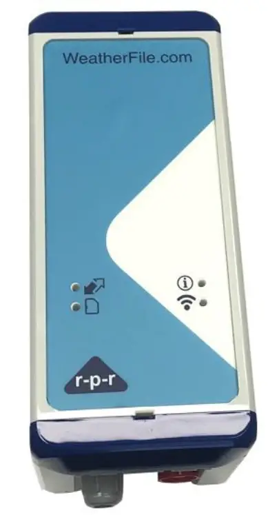
WCU WiFi/Mobile Indicators
Sensor Data
If the WCU is connected to a sensor and is receiving data from the sensor, this LED will be illuminated green.
SD Card
This LED is illuminated green if an SD card is inserted into the datalogger and can be written to.
WiFi
The WiFi LED will be illuminated green if the WCU has connected to an Access point. The following table is provided so that the WiFi credentials in use can be recorded for later reference, if required.
| WiFi Network Name (SSID) | |
| WiFi Key (password) |
Note: When the WCU is supplied with a 4G modem, the SSID will be the same as the WCU serial number (without the variant prefix).
Status
In normal operation, the status LED should not be illuminated. When power is initially connected to the WCU, the status LED may blink every 2 seconds for about 30 seconds until the WCU has acquired the current time, either over the internet or from a GPS source.
WCU LAN Indicators
There are no external indicators on the WCU LAN variant. Please refer to the W100 User Manual for further details of the internal indicators on the W100 SpaceLogger within the WCU. https://r-p-r.co.uk/downloads/spacelogger/020SL045_1_User_Manual.pdf
Connections
Power Connection
Power is connected to the WCU via the red Binder connector. This is a push fit connector; DO NOT twist this connector when either inserting or removing the power connection.
Sensor Connection
The sensor cable egresses the WCU via a 12mm cable gland and is terminated internally within the WCU. This is to facilitate ease of cable routing to the sensor where the cable may need to pass through walls etc as it minimises the size of any hole that may need to be provided. In normal use, the cable gland should be fully tightened to prevent moisture ingress to the WCU. A 17mm spanner should be used to tighten the cable gland.
LAN Connection
The LAN cable passes through a cable gland to minimise the potential for moisture ingress to the WCU. The LAN cable is only provisioned on the WCU-LAN variant of the product. The LAN cable is terminated internally in the WCU as shown in section 3.5.3.
Installing the WCU
To work inside the WCU, the following tools are required:
- 4mm Flat bladed screwdriver
- 2mm Flat bladed screwdriver
- 17mm open spanner for the sensor cable gland
- 30mm open spanner for the LAN cable gland
The main reasons to need to open the WCU are:
- Terminating the sensor cable
- Terminating the LAN cable (where applicable)
- Using WPS mode to connect to a WiFi access point
- Pole mounting the WCU
- Changing the SIM (where applicable)
Opening the WCU
Note: Before opening the WCU it is recommended that power is disconnected from the system.
Using a 4mm flat bladed screwdriver, pop open the lower retention clip of the WCU (nearest the connectors as shown) by pushing vertically down with the screwdriver in the centrally located slot and open the WCU lid, as indicated in Figure 2 below.
Note: Reasonable force can be applied.
Inside the WCU
DataLogger
Depending upon the variant of the WCU supplied, the unit will either contain a W50 SpaceLogger in the lid of the WCU, or a W100 SpaceLogger within the main compartment of the WCU.
Power Control & Management Board
In the base of the WCU is the Power Control and Management board, as shown in the figure below. In general, it should only be necessary to make connections to P6; the other connections will have been pre-configured as necessary prior to shipment.
- JP1: The topmost of the two jumpers, and is used to select the presence of the termination resistor on the RS485 to RS232 converter. Most RS485 sensors are point-to-point and do not support multiple sensors on one cable, and the Power Conditioning and Management Board is almost certainly the end of the chain, so in 99% of cases, the termination resistor will be enabled. Default : Termination Resistor Enabled.
- JP2: The bottom of the two jumpers, and is used to select the transmission protocol the sensor is using. When using an RS485/422/NMEA sensor, JP2 can enable the RS485 to RS232 converter so that the logger can correctly receive data. When using RS232, JP2 can disable the converter and instead allow RS232 passthrough to the logger. Default: RS232

- P4: Pin 3 (bottom terminal) can be used for terminating signal screen.
- P6: Sensor connection terminal, provides connection options for RS232, RS485/422 and NMEA sensors, as well as power. Nominally +12V, the power rail is the filtered and smoothed supply input voltage. The sensor supply can be switched on and off by the PCMB. 12 connections.
- P2: USB power connector
Mobile WiFi Hotspot
The WCU Mobile version of the product will be supplied with a Mobile WiFi hotspot inserted into the P2 connector.
Terminating the Sensor Cable
A 12-pin connector block is provided (P6) that will accept cables of 20 to 24 AWG. To insert a cable into the terminal block, fully depress the button above the relevant position using a small flat bladed screwdriver, insert ~10mm of the bare wire into the terminal block and then release the button.
RS232
For RS232 sensors, the connections to P6 should be made as shown below. The cable colours are shown for a Gill WindSonic WS-1. Cable colours for other sensors may vary. Please refer to the supplied system wiring instructions.

Note: Signal screen can be terminated to P4 pin 3 (if present)
RS422/RS485
For RS485 sensors, the connections to P6 should be made as shown below. The cable colours are shown for an RS485 cable as supplied by RPR Ltd. Cable colours may vary. Please refer to the supplied system wiring instructions. Note that for an RS422/RS485 cable, the pairs should always be twisted. One pair should be used for power (if applicable), and one pair for data.

Note: Signal screen can be terminated to P4 pin 3 (if present).
Terminating the LAN Cable
For the WCU LAN variant, the WCU is supplied with a cable gland through which an unshrouded RJ48 connector will fit. The LAN cable should be fed through the cable gland and then inserted into the appropriate location on the internal datalogger provided.
Connecting to the Internet
For correct operation of the WCU, it should have access to the public internet either via the mobile network, or via a WiFi Access Point, or via a wired ethernet connection to a router.
Mobile Network
The WCU for Mobile Cellular Networks is supplied with a Mobile Router Hotspot. The specific model can be changed as required for regional variations etc.
SIM and APN
Please refer to the WCU Router Administration Guide, 016SL113, for details of how to access the SIM and how to change the APN. This should only be necessary where the SIM has been provided by the customer. Where the SIM has been provided by RPR Ltd it will have been pre-configured to connect to the internet using the appropriate APN for the relevant mobile network operator.
WiFi
The WiFi variant of the WCU should be connected to a WiFi Access Point that has access to the public internet. To connect to the WiFi Access Point, it is recommended to use WiFi Protected Setup mode (WPS). Where this is not possible, the WiFi details can be supplied to the WCU using the SD card. diagram below shows the location of the SD card and WPS button in the lid of the WCU-WiFi variant.

WiFi configuration using WPS Mode
The following steps should be taken to connect the WCU to the WiFi Access Point using WPS.
- Open the WCU and locate the red WPS button in the lid of the WCU.
- Start WPS mode on the WiFi Access Point
- Press and hold the WPS button until the WiFi LED starts to flash. The WCU will also emit a short two tone beep to indicate it is in WPS mode. At this point, release the WPS button.
- The WCU will reset itself and connect to the WiFi Access Point.
- If successful, the WiFi LED will stop flashing, remain illuminated
- If unsuccessful, the WCU will reset again and the WiFi LED will not be illuminated
For further details, please refer to the W50 Users Manual, 018SL068, which can be found on the RPR web site at:
https://r-p-r.co.uk/downloads/spacelogger/018SL068_3_SpaceLogger.W50.Wireless_User_Manual.pdf
WiFi Configuration using the SD card
The following steps should be taken to configure the WCU to connect to a WiFi Access Point if WPS mode cannot be used.
- Obtain the WiFi Access Points Network Name (SSID) and password
- Power down the WCU
- Open the WCU and locate the microSD card in the lid of the WCU
- Remove the microSD card from the WCU
- Create a file in the root directory of the microSD card called SETUP.TXT
- In the SETUP.TXT file, add the two following lines SSID=”WiFi Network Name” WIFI_KEY=”WiFi password”
- Replace the microSD card into the WCU
- Power up the WCU
- If successful, the WiFi LED will be illuminated
- For further details, please refer to the W50 Users Manual, 018SL068, which can be found on the RPR web site at:
https://r-p-r.co.uk/downloads/spacelogger/018SL068_3_SpaceLogger.W50.Wireless_User_Manual.pdf
LAN
The WCU LAN variant should be connected to a router using a CAT5 cable. The router should provide the WCU with an IP address using DHCP, and should provide access to the internet. For further details, please refer to the W100 Users Manual, 020SL045, which can be found on the RPR web site at: https://r-p-r.co.uk/downloads/spacelogger/020SL045_1_User_Manual.pdf
Closing the WCU
To close the WCU, close the lid and shut the lower retention clip fully.
Mounting Options
Wall Mounting
Wall mounting feet are provided so that the WCU can be mounted without needing to open the WCU. The feet should be attached to the WCU using self tapping screws provided. The feet should either project either side of the unit, or top and bottom of the unit.
The fixing centres are:
- 91 x 168mm (feet projecting to the sides)
- 64 x 195mm (feet projecting top and bottom)
No fixings are provided to screw the WCU to the wall, since this will depend upon the material and thickness to which the WCU is being attached e.g. brick, plasterboard, wood, plastic etc. See Appendix A1 for illustrations of the wall mounting options.
Pole Mounting
An optional pole mounting kit is available, to mount the WCU to a pole of up to 50mm diameter. Note that when pole mounting, it is necessary to open the unit to attach the pole mounting plates. See Appendix A2 for illustrations of the pole mounting kit.
Operation
In normal operation there should be no need to access the WCU itself, since the sensor data is sent to the internet and is available on WeatherFile.com.
WeatherFile.com
In most cases, the sensor data will be viewed using WeatherFile.com. Open WeatherFile.com. If the Weather station is private, log in to WeatherFile.com.
Weather Station Data
To view the data from the station using the map view, use the mouse and/or zoom buttons to locate the station on the map. It will be a blue dot showing wind direction and speed.

Click on any dot to show the basic information about any station, and then click on the ‘View live graphs and data’ link to show more detailed data

Alternatively, click on ‘Locations’ in the menu bar and select the desired station from the list of locations presented.

Local Display
The Local Display provides a means to view the data being provided by the sensor to the WCU on a web browser, via the LAN or WiFi network. In this case, it is necessary that the viewing device is connected to the same LAN as the WCU. The Local Display page will automatically adjust to present the range of parameters being provided by the sensor.
Title Bar
The Title bar will display the WCU name, which will typically be the same as the serial number of the WCU. It also displays the current time, as provided by the browser.
Live Wind Direction
The current wind direction is updated approximately every 2 seconds, with the most recent 3 second gusting windspeed. Then wind direction is displayed in the centre of the icon, with a ‘wind sock’ or flag style representation of the direction which rotates around the display.
Live Wind Speed
The current speed is also updated approximately every 2 seconds in the same manner as the wind direction.
Average Data
Below the current readings is a section that will update whenever the average data changes. For wind speed data, this will display the low, average and high wind speed readings. For wind direction data, this will display the backed (anticlockwise), average and veered (clockwise) wind directions. Any further parameters, such as temperature, humidity etc will be displayed below the wind data, if available.
Display Options
The display options allow the wind speed units to be selected as either meters per second, kilometres per hour, miles per hour or knots.
SpaceLogger Launcher
The SpaceLogger Launcher software may be used to find WCUs on the LAN and thus to connect to the Local Display. Note that SpaceLogger Launcher can only find WCUs which are connected to the same LAN as the machine running SpaceLogger Launcher. The SpaceLogger Launcher software is available for Windows only, and can be downloaded from https://r-p-r.co.uk/WeatherFile/WeatherFile-communication-unit.php
Once installed, SpaceLogger Launcher will display a list of the available devices on the LAN. Simply double click on the relevant device, and then click on the link to the Local Display.

Basic Troubleshooting
| Issue | Suggestion |
| No GeoTag on WeatherFile.com | System is Private and only visible if logged in. System does not have an internet connection.
System is currently turned off (may only be on periodically). |
| GeoTag is greyed out | The unit stopped sending data within the last hour. |
| No reported wind direction | The windspeed has dropped below the minimum threshold for the sensor fitted |
| No LEDs visible | WCU-LAN: LEDs are only visible internally. WCU-WiFi/Mobile: No power |
Specifications
| Physical | |
| Enclosure dimensions including connectors | 191mm x 80mm x 90mm |
| Enclosure Material | Polycarbonate UL94VO |
| Connections | Power: Binder 720 Series
Sensor: Screwless Terminal Block via Cable Gland LAN: RJ45 via Cable Gland (LAN Version Only) |
| WCU Weight excluding Mounting and Cables | Mobile Version: 0.42kg WiFi Version: 0.39kg LAN Version: 0.45kg |
| Optional Pole Mounting Brackets | Stainless Steel. Maximum
Pole Diameter 50mm |
| Optional Wall Mounting Brackets | Fixing Centres 91 x 168mm or 64 x 195mm |
| Sensor Input | |
| Sensor types | Gill Instruments: WindSonic, WindObserver, WindMaster (LAN WCU), WindUltra, MaxiMet, MetConnect, & MetPak
NMEA0183 compatible wind sensors.
Please Contact RPR if you wish to use other sensors |
| Transmission standard | RS232 and RS485 compatible, 8 bits and no parity |
| Wireless/network Connectivity | |
| Wi-Fi (1) | Wi-Fi Certified 2.4GHz IEEE 802.11b/g Security WPA2-PSK, WPA |
| Mobile 3G/4G (2) | LTE FDD: Band 1(2100 MHz)/Band 3(1800
MHz)/Band 7(2600MHz)/Band 8(900MHz)/Band 20(800 MHz), |
| LAN (3) | RJ45 connector 10/100 Base-T |
| Data Storage | |
| Data Storage Card | Removable micro SDHC card |
| Data Capacity | 8 GB (standard) |
| Remote Cloud Storage | Data stored on the WeatherFile.com 2 years as standard |
| Environmental | |
| Operating Temperature range | : -10°C to +55°C |
| Storage: | -40°C to +70°C |
| Enclosure Protection | Mobile & WiFi Version IP67 LAN Version IP65 |
| Audible / Visual Indicators | |
| LED indicators, Mobile & WiFi versions | SD card status, Data input status, Wireless connection status |
| Audible beep | Power on, No SD card |
| Power | |
| Power Requirement | 12V DC ± 10% |
| Current @ 12V DC | 300 mA typical |
APPENDICES
A1 Wall Mounting

A2 Pole Mounting

A3 UK DECLARATION OF CONFORMITY
We, Richard Paul Russell Limited of The Lodge
Unit 1 Barnes Farm Business Park
Barnes Lane
Milford-on-Sea
Hampshire SO41 0AP
United Kingdom
Declare under our sole responsibility that the product: WeatherFile Communications Unit
Manufactured by: Richard Paul Russell Limited
to which this declaration relates, is in conformity with the protection requirements of Electromagnetic Compatibility Regulations 2016 on the approximation of the laws relating to electromagnetic compatibility. This Declaration of Conformity is based upon compliance of the product with the following harmonised standards:
| Emissions Radiated emissions
(30 MHz to 6.0 GHz) Conducted emissions |
EN 55032:2015 & ETSI EN 301 489-1:V2.2.0:2017 | CISPR 32:2015 |
| Radiated spurious emissions
(1GHz to 12.75 GHz) |
ETSI EN 300 328:V2.1.1:2016† | ETSI EN 300 328:V2.1.1:2016
Clause 5.4.9† |
| Mains harmonics | EN 61000-3-2:2014 | EN 61000-3-2:2014, Class A |
| Mains voltage flicker
(dmax=4%) |
EN 61000-3-3:2013 | EN 61000-3-3:2013 |
| Immunity Electrostatic Discharge | EN 61000-4-2:2009 | |
| Radiated RF Immunity | EN 61000-4-3:2006 inc A1:2008 & A2:2010 | |
| EN 55035:2017 & ETSI EN 301 489-1:V2.2.0:2017 | ||
| Fast transient Bursts | EN 61000-4-4:2012 | |
| Surge | EN 61000-4-5:2014 | |
| Conducted Immunity | EN 61000-4-6:2014 | |
| Voltage dips & interruptions (PLD) | EN 61000-4-11:2004 inc A1:2017 |
Signed by:
Richard Paul Russell – Director
Date of Issue: 01 January 2021 Place of Issue: The Lodge
Unit 1 Barnes Farm Business Park
Barnes Lane
Milford-on-Sea
Hampshire SO41 0AP
United Kingdom.
A4 CE Declaration of Conformity
EC DECLARATION OF CONFORMITY
ACCORDING TO COUNCIL DIRECTIVE
2014/30/EC.
We, Richard Paul Russell Limited of The Lodge
Unit 1 Barnes Farm Business Park
Barnes Lane
Milford-on-Sea
Hampshire SO41 0AP
United Kingdom.
Declare under our sole responsibility that the product: WeatherFile Communications Unit
Manufactured by: Richard Paul Russell Limited
This Declaration of Conformity is based upon compliance of the product with the following harmonised standards:
| Radiated emissions
(30 MHz to 6.0 GHz) Conducted emissions |
EN 55032:2015 & ETSI EN 301 489-1:V2.2.0:2017 | CISPR 32:2015 |
| Radiated spurious emissions
(1GHz to 12.75 GHz) |
ETSI EN 300
328:V2.1.1:2016† |
ETSI EN 300 328:V2.1.1:2016
Clause 5.4.9† |
| Mains harmonics | EN 61000-3-2:2014 | EN 61000-3-2:2014, Class A |
| Mains voltage flicker
(dmax=4%) |
EN 61000-3-3:2013 | EN 61000-3-3:2013 |
| Electrostatic Discharge | EN 61000-4-2:2009 | |
| Radiated RF Immunity | EN 61000-4-3:2006 inc A1:2008 &
A2:2010 |
|
| EN 55035:2017 & ETSI EN 301
489-1:V2.2.0:2017 |
||
| Fast transient Bursts | EN 61000-4-4:2012 | |
| Surge | EN 61000-4-5:2014 | |
| Conducted Immunity | EN 61000-4-6:2014 | |
| Voltage dips & interruptions (PLD) | EN 61000-4-11:2004 inc A1:2017 |
A5 FCC Declaration of Conformity
WeatherFile Communications Unit has been tested for compliance with FCC standards FCC/CFR 47: Part 15. This device complies with Part 15 of the FCC Rules. Operation is subject to the following two conditions: (1) this device may not cause harmful interference, and (2) this device must accept any interference received, including interference that may cause undesired operation. The user is cautioned that changes or modifications not approved by the responsible party could void the user’s authority to operate the equipment, in line with the FCC guidelines.
This equipment has been tested and found to comply with the limits for a Class B digital device, pursuant to part 15 of the FCC Rules. These limits are designed to provide reasonable protection against harmful interference in a residential installation. This equipment generates, uses and can radiate radio frequency energy, and if not installed and used in accordance with the instructions, may cause harmful interference to radio communications. However, there is no guarantee that interference will not occur in a particular installation. If this equipment does cause harmful interference to radio or television reception, which can be determined by turning the equipment off and on, the user is encouraged to try to correct the interference by one or more of the following measures:
- Reorient or relocate the receiving antenna.
- Increase the separation between the equipment and receiver.
- Connect the equipment into an outlet on a circuit different from that to which the receiver is connected.
- Consult the dealer or an experienced radio/TV technician for help.
To satisfy FCC RF Exposure requirements for mobile and base station transmission devices, a separation distance of 20 cm or more should be maintained between the antenna of this device and persons during operation. To ensure compliance, operation at closer than this distance is not recommended. The antenna(s) used for this transmitter must not be co-located or operating in conjunction with any other antenna or transmitter.
A6 WEEE
The WEEE directive places an obligation on all EU-based manufacturers and importers to take-back electronic products at the end of their useful life. Richard Paul Russell Ltd accepts its responsibility to finance the cost of treatment and recovery of redundant WEEE in accordance with the specific WEEE recycling requirements. This symbol on the product or on its packaging indicates that, within the EU, the product must NOT be disposed of with normal household waste. Instead, it is the end user’s responsibility to dispose of their waste equipment by arranging to return it to a designated collection point for the recycling of WEEE. By separating and recycling waste equipment at the time of disposal, natural resources will be conserved and it will be ensured that the equipment is recycled in a manner that protects human health and the environment. For more information about where you can send your waste equipment for recycling, please contact your local council office or visit our website www.r-p-r.co.uk.
A7 RoHS
(The Restriction of the Use of Certain Hazardous Substances in Electrical and Electronic Equipment Regulations 2006
SpaceLogger.W50 has been designed to comply with EU Directive 2011/65/EU on RoHS regulations. The unit is assembled from compliant components.
RoHS is often referred to as the lead-free directive, but it restricts the use of the following six substances:
- Lead (Pb)
- Mercury (Hg)
- Cadmium (Cd)
- Hexavalent chromium (Cr6+)
- Polybrominated biphenyls (PBB)
- Polybrominated diphenyl ether (PBDE)
- PBB and PBDE are flame retardants used in some plastics.
Guarantee
System components are warranted for a period of 24 months from the original date of purchase, against defective materials and workmanship. In the event that warranty service is required, please contact Richard Paul Russell Ltd.
This warranty is only valid if, when warranty service is required, a full description of the fault is provided and presented with the original invoice, and the serial number(s) on the component has not been defaced. Richard Paul Russell Ltd’s liability is limited to items of its own manufacture, and it does not accept liability for any loss resulting from the operation or interpretation of the results from this equipment.
This warranty does not cover any of the following:
- Periodic check ups, maintenance and repair or replacement of parts due to normal wear and tear.
- Cost relating to transport, removal, or installation of the component.
- Misuse, including failure to use the component for its normal purpose or incorrect installation.
- Damage caused by Lightning, Water, Fire, Acts of God, War, Public Disturbances, incorrect supply voltage or any other cause beyond the control of Richard Paul Russell Ltd.
- Units which have been repaired or units altered by a party other than Richard Paul Russell Ltd’s employees or agents without prior written consent from Richard Paul Russell Ltd
- In no event shall Richard Paul Russell Ltd be liable under any circumstances for any direct, indirect or consequential damages, any financialloss or any lost data contained in any product (including any returned product), regardless of the cause of loss. Richard Paul Russell Ltd products are not warranted to operate without failure. Richard Paul Russell Ltd’s products must not be used in life support systems or other application where failure could threaten injury or life.
- The Customers statutory rights are not affected by this warranty. Unless there is national legislation to the contrary, the rights under this warranty are the customer’s sole rights and Richard Paul Russell Ltd shall not be liable for indirect or consequential loss or damage to any other related equipment or material.
©2021-24 Richard Paul Russell Ltd, The Lodge, Unit 1 Barnes Farm Business Park, Barnes Lane, Milford on Sea SO41 0AP
Tel +44 (0) 1590 641223
e-mail: sales@r-p-r.co.uk
web: www.rpr.co.uk
Documents / Resources
 |
r-p-r 016SL123 Weather File Communications Unit [pdf] User Manual W8, 016SL123, 016SL123 Weather File Communications Unit, 016SL123, Weather File Communications Unit, File Communications Unit, Communications Unit, Unit |


