POWER PROBE DM600MAX High Performance Multimeter User Manual

![]() Read First
Read First
![]() Safety Information
Safety Information
Understand and follow operating instructions carefully.use the meter only as specified in this manual; otherwise,the protection provided by the meter may be impaired.
![]() WARNING
WARNING
This identifies hazardous conditions and actions that could cause BODILY HARM or DEATH. To avoid possible danger, follow below guidelines
- Use the meter only as specified in this manual or the protection by the meter might be impaired.
- Never operate the meter with the cover removed or the case opened.
- To avoid false readings that can lead to electric shock and injury, replace battery as soon as low battery indicator blinks.
- Use caution with voltages above 30VAC rms, 42VAC peak, or ±30VDC. These voltages pose a shock hazard.
- When using test leads or probes, keep your fingers behind the finger guards.
- Remove test lead from meter before opening the battery door or meter case.
- Always use proper terminals, switch position, and range for measurements.
- Do not apply more than the rated voltage, as marked on meter, between terminals or between any terminal and earth ground.
- Do not use the High Frequency Rejection (Low Pass Filter) option to verify the presence of hazardous voltages. Voltages greater than what is indicated may be present. First, make a voltage measurement without the filter to detect the possible presence of hazardous voltage. Then select the filter function.
- To avoid possible electric shock or personal injury, never attempt an in-circuit current measurement where the open circuit reference to earth is greater than 1000V.
- Replace the fuse as soon as the meter shows blown fuse screen.
- Only replace the blown fuse with the proper rating as specified in this manual.
- Do not use the meter around explosive gas, vapor or dust.
- To reduce the risk of fire or electric shock do not expose this product to rain or moisture.
- Do not attempt a current measurement when the open voltage is above the fuse protection rating. Suspected open voltage can be checked with voltage function.
- Never attempt a voltage measurement with the test lead inserted into the A input terminal.
Symbols as marked on the Meter and Instruction manual

Unsafe Voltage
To alert you to the presence of a potentially hazardous voltage, when the Tester detects a voltage ≧ 30 V or a voltage overload (OL) in Voltage mode. The ![]() symbol is displayed.
symbol is displayed.
Maintenance
Do not attempt to repair this Meter. It contains no user service-able parts. Repair or servicing should only be performed by qualified personnel.
Cleaning
Periodically wipe the case with a dry cloth and detergent. Do not use abrasives or solvents.
Introduction
The Meter Description
Front Panel Illustration
- LCD display
- MENU BAR
- F1
- F2/UP
- F3/Enter
- BACK
- Range/DOWN
- HOLD
- Rotary switch
- Input terminal for 0 to 10A current measurement
- Input terminal for 0 to 400mA/μA current measurement
- COM input terminal for ground
- Input terminal for voltage, frequency, resistance, continuity, diode, capacitance and temperature measurements
Attention


Rotary switch


MENU Bar is used to switch the measurement mode and activate functions. Press F1, F2, and F3 to execute the corresponding function or enter the sub-level of MENU Bar.
Pressing BACK button can switch the MENU Bar back to the top level.
1. Mode
The multifunction on the rotary switch can be toggled by pressing the MODE button. In DCV mode, pressing the MODE button allows measurement of the Duty cycle and Pulse Width.

2. SETUP
After entering SETUP mode, use the up and down keys to select the item you want to modify. Press ENTER to enter the item and use the up and down keys to adjust the settings. After making the changes, press ENTER to save. Pressing the BACK button will exit without saving the modified settings.


● APO
If you don’t operate the rotary switch or buttons for a specified time, the meter will turn off automatically to save the power of batteries. The default APO timer is 10 minutes. In setup mode, you can change the APO timer.

When you open this function, the status will be displayed in the top right corner of the screen.
![]()
● Buzzer
The meter equip a 2.7kHz tone buzzer. Valid button press: Beep once. And invalid button press: Beep twice. In setup mode, you can turn on or off the buzzer. But the buzzer in continuity check cannot be turn off.
When you close this function, the status will be displayed in the top right corner of the screen.
![]()
● Display Resolution
This meter have two display resolution: low resolution (3¾-digit mode) and high resolution (4¾-digit mode). The low resolution is set to default. You can setup the resolution in setup mode.
In high resolution function, the status will be displayed on the screen

● Wireless Link
You can connect the meter to Android and iOS device with our App to show the reading remotely and download LOG / MEMORY data.
When you open this function, the status will be displayed in the top right corner of the screen.

App Store: https://apps.apple.com/us/app/powerprobe-link/id6476737385
Google Play: https://play.google.com/store/apps/details?id=com.powerprobe.app.powerprobelink
• Chart
The chart under the screen can be selected.
Bar graph
Before displaying the numerical value, quickly show an approximate value within the range.

Trend graph
Check the stability status of the readings within the range.

3. Function
When you press the FUNCTION key, the MENUBAR will display three options.

• Relative Δ
When measuring, you can use the relative (Δ) mode to subtract the offset.
Pressing the REL key activates the REL function, displaying the Δ symbol at the secondary display. The number following the Δ symbol represents the offset that has been subtracted on the main display. The REL key, once activated, will change color, and pressing it again will deactivate the function.

Even after activating the function, you can still press the BACK key to return to the default MENUBAR state.

• Relative %
When measuring, you can use the relative (%) mode to calculate the relative percent value. The relative percent value is define as below:
![]()
In this mode, meter records the present reading as reference and shows it on the secondary display. The relative (%) mode calculate the relative percent value from each reading, and shows result on the main display.

• Memory

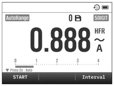
• SAVE/Auto-Saving
SAVE function can let you store the current primary reading into the meter. Press SAVE to store the reading.
You can also operate the Auto-Saving mode to automatically save new reading by long press SAVE. When you use the probes to measure a new stable reading that is higher than the minimum trigger threshold, the meter will automatically save it. OL Reading won’t be saved. You can see the current number of data entries by the number displayed above. When the maximum data storage limit is reached, a “Memory FULL” warning will appear.

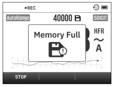
• Data Logger
You can record a lot of reading to memory in a long time, then analyze and plot graph. The meter can store maximum 40,000 data in memory. The recorded data amount shows on the secondary display. When the LOG function starts recording, a ● REC icon will appear in the top left corner of the screen.
In LOG function, You can setup the record rate of logger. Press the INTERVAL button to adjust using the UP and DOWN buttons.The record rate can be set from 1 sec and 600 sec. The error of timer is less than 3 seconds per hour.

You can see the current number of data entries by the number displayed above. When the maximum data storage limit is reached, a “Memory FULL” warning will appear. Press any button to exit.
![]() Warring
Warring
Each time a new log is recorded, the previously saved data will be deleted.

When “Memory FULL” appears, you can enter SETUP to clear data.

• View the records
Press VIEW MEM or VIEW LOG to show the stored data. Long-press UP and DOWN allows for quick screen scrolling. Press F1 allows you to quickly jump to the first data entry, while F3 allows you to quickly jump to the last data entry. Press BACK to exit.

Making Basic Measurements
Preparation and Caution Before Measurement
Observe the ![]() rules Warnings and
rules Warnings and ![]() Cautions.
Cautions.
![]() CAUTION
CAUTION
- When connecting the test leads to the DUT (Device Under Test) connect the common test leads before connecting the live test leads; when removing the test leads, remove the live test leads before removing the common test leads.
Measuring AC Voltage and DC Voltage
This meter have true rms readings, which are accurate for distorted sine waves and other waveforms (with no dc offset) such as square waves, triangle waves, and staircase waves.
The ranges of measuring voltage are 40mV, 400mV, 4V, 40V, 400V and 1000V. To select the mV range, turn the rotary switch to mV position.
For best accuracy when measuring the DCmV, touch the probe tips together and read the DC offset. If necessary, you can use the relative (Δ) mode to automatically subtract this value.
ACV

mV

In AC mode, the frequency may be show dashes if the signal is smaller than the min. sensitivity and trigger level. Please see “Sensitivity and Trigger level” table in the specification section of Frequency.

Measuring Voltage in LoZ Mode
![]() CAUTION
CAUTION
- Do not use the LoZ mode to measure voltages in circuits that could be damaged by this mode’s low impedance.
To eliminate ghost voltages, the meter’s LoZ mode presents a low impedance across the leads to obtain a more accurate measurement. In this mode, meter will automatic measure input signal which is AC or DC and determine range.
To use the LoZ mode, turn the rotary switch to LoZ position

Measuring AC and DC Current
![]() WARNING
WARNING
- Always use proper terminals, switch position, and range for measurements.
- To avoid possible electric shock or personal injury, never attempt an in-circuit current measurement where the open circuit potential to earth is greater than 1000V.
- Only replace the blown fuse with the proper rating as specified in this manual.
![]() CAUTION
CAUTION
- Replace the fuse as soon as the indicator (FUSE) appears.
To measure current, you must break the circuit under test, then place the meter in series with the circuit.
The ranges of measuring current are 40mA, 400mA, 4A and 10A. AC current is displayed as an rms value. Insert the black lead into the COM terminal. For currents less than 400 mA, insert the red lead into the mA/μA terminal. For currents above 400 mA, insert the red lead into the A terminal.
A/mA


A/mA

In AC mode, the frequency may be show dashes if the signal is smaller than the min. sensitivity and trigger level. Please see “Sensitivity and Trigger level” table in the specification section of Frequency.
Plugging 30A probe to measure up to 30A current.

Measuring Frequency
The meter measures the frequency of a voltage or current signal by counting the number of times the signal crosses a threshold level each second.
This function only can be operated in AC voltage and current measurements. The ranges of measuring frequency are 400Hz, 4kHz, 40kHz and 100kHz.
If a reading shows as 0 Hz or is unstable, the input signal may be below or near the trigger level. The detail of frequency trigger level refer to the electrical specifications.
To use the frequency function, press MODE in the AC measurements, and press Hz key, once activated, will change color, and pressing it again will deactivate the function.

Make High Frequency Rejection Measurement (HFR)
![]() WARNING
WARNING
- Do not use the High Frequency Rejection (Low Pass Filter) option to verify the presence of hazardous voltages. Voltages greater than what is indicated may be present. First, make a voltage measurement without the filter to detect the possible presence of hazardous voltage. Then select the filter function.

The High Frequency Rejection mode equip a Low Pass Filter in the AC measurements. The cut-off frequency (-3dB point) of Low Pass Filter is 800Hz.
To use the frequency function, press MODE in the AC measurements, and press HFR key, once activated, will change color, and pressing it again will deactivate the function.

Duty Cycle and Pulse width Measurement
The meter measures the positive half-cycle of a square wave, Display the ratio(%) of the positive half-cycle to the entire period or seconds(ms) as the main readings of Duty Cycle and Pulse Width. The secondary reading show the frequency of the waveform at the same time. If a reading shows as 0% , 0ms or is unstable, the input signal may be below or near the trigger level. The detail of frequency trigger level refer to the electrical specifications.

To use Duty cycle function, turn the rotary switch to the DCV position, then press F1 to change measuring mode.

Measuring Resistance
![]() CAUTION
CAUTION
- To avoid possible damage to the meter or to the equipment under test, disconnect circuit power and discharge all high voltage capacitors before measuring resistance.

The ranges of measuring resistance are 400Ω, 4kΩ, 40kΩ, 400kΩ, 4MΩ, and 40MΩ.
The test leads may be add 0.1Ω to 0.2Ω of error to resistance measurements. To test the leads, touch the probe tips together and read the resistance of the leads. For best accuracy, you can use the relative (Δ) mode to automatically subtract this value.
High-resistance (>10MΩ) readings are susceptible to electrical noise. To smooth out most noisy readings, enter the MAX/MIN recording mode; then step to the average (AVG) reading.
Continuity Check
![]() CAUTION
CAUTION
- To avoid possible damage to the meter or to the equipment under test, disconnect circuit power and discharge all high voltage capacitors before testing continuity.
The continuity check features a buzzer that sounds as long as a circuit is complete. The buzzer allows you to quick continuity checks without watching the display.
When measuring resistance is less than threshold, the buzzer sounds. You can setup the threshold in setup mode.
The continuity threshold is default 30Ω.

To use continuity check, turn the rotary switch to resistance position, then press F1 to change measuring mode.
Testing Diodes

Use the diode test to check diodes, transistors, silicon controlled rectifiers (SCRs), and other semiconductor devices.
For forward-bias readings on any semiconductor component, place the red test lead on the component’s positive terminal and place the black lead on the component’s negative terminal. In a circuit, a good diode should still produce a forward-bias reading of 0.5V to 0.8V.
Measuring Capacitance
![]() CAUTION
CAUTION
- To avoid possible damage to the meter or to the equipment under test, disconnect circuit power and discharge all high-voltage capacitors before measuring capacitance. Use the dc voltage function to confirm that the capacitor is discharged.

To improve the accuracy of measurements less than 1000nF, you can use the relative (Δ) mode to subtract the residual capacitance of the leads.
To use capacitance, turn the rotary switch to diode position, then press F1 to change measuring mode.
Measuring Temperature
![]() CAUTION
CAUTION
The accuracy specifications are only applicable under lowest brightness within 15-minute operation time when the temperature is stable within ±1°C and the instrument has been left for more than 2 hours in OFF state.
The meter measures the temperature of a K-Type thermocouple. Readings outside of these ranges show “OL” on the display. When there is no thermocouple connected, the display also shows “OL”

To use temperature measurement, turn the rotary switch to mV position, then press MODE to select measuring mode.
HOLD
When you press the HOLD key, the MENUBAR will display three options.
In the normal measurement mode, you can press the HOLD button to freeze the value on the screen.

• Auto-HOLD
When measuring, in the HOLD function, you can press F3 to start the Auto-Hold mode. In this mode, the meter holds reading and shows it on the secondary display.
If the difference between new reading and hold reading is bigger than 5d (3¾-digit mode), and new reading is also stable, then meter automatically holds a new reading on the secondary display.
When reading is smaller than Auto-Hold limit, or reading is OL, the Auto-Hold mode is not working.

To exit Auto-Hold mode, press F3 again. When Auto-Hold mode is disable, the hold mode is not update any new reading.

• Peak-HOLD
The Peak-Hold mode records wave peak maximum and minimum input values.

To use the Peak-Hold mode, in the HOLD function press the PeakHOLD button to enable the Peak-Hold mode in the AC or DC measurements. In this mode, you can see both peak MAX or MIN value. Each time the maximum or minimum value is exceeded, the value at the bottom will be updated.
You can press ⏸️ the Freeze button to pause updating the values at the bottom; an icon will appear in the top left corner.

Pressing the Restart button will update the values at the bottom to the latest readings.
To exit Peak-Hold mode, press cancel.
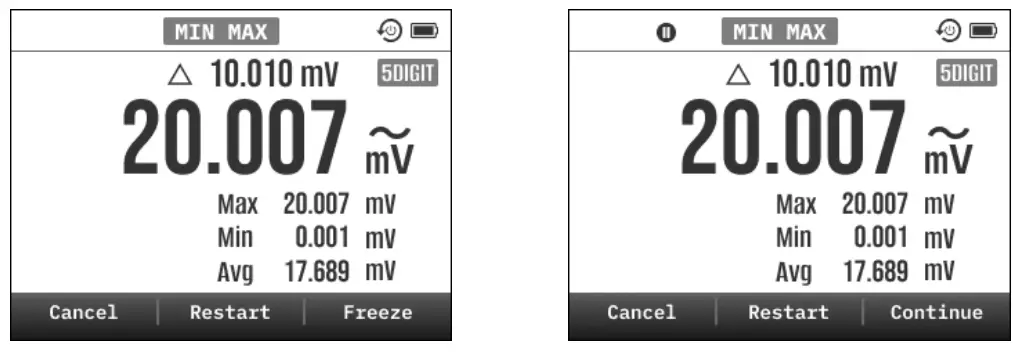
• Maximum / Minimum
When measuring, you can record the maximum, minimum and average value of reading.
In the HOLD function and press MIN MAX to use maximum / minimum mode. In this mode, the meter records each data to compare the maximum and minimum value. Also, meter calculates the average of reading.
When maximum / minimum record mode running, if you wants to pause recording, press the Freeze button. Press again to continue.
To exit maximum / minimum record mode, press the CANCEL button.
Fuse Replacement

Low Battery and Battery Replacement
Replace the battery as soon as the low battery indicator appears, to avoid false reading. Refer to the following figure to replace the batteries

![]() CAUTION
CAUTION
- Remove test leads from Meter before opening the battery cover or Meter case
Accessories (standard)
- Alligator clip set
- Test lead set – CAT III 1000V, CAT IV 600V, 10A, 120cm cable length
- K Type Thermocouple
Accessories (option)
- 30A Test Probe with alligator clip and built-in 30A Fuse
CAT III 1000V, CAT IV 600V, 30A
30A 1000V Fast-acting fuse.
120cm cable length - RPM Trigger Pickup (inductive)
Environmental Conditions
- The accuracy specification is given as ± (% of reading + counts of least significant digit) at 23°C ± 5°C, with relative humidity less than 80% R.H., and is specified for 1 year after calibration.
- Temperature Coefficient: 0.1 * (Specified accuracy) / °C, < 18°C, > 28°C
- Operating Temperature: -10°C to 30 °C (≤ 80% R.H.)
30°C to 40 °C (≤ 75% R.H.)
40°C to 50 °C (≤ 45% R.H.) - Storage Temperature: -20°C to 60 °C (≤ 80% R.H., no batteries)
- Operating Altitude: 2000m (6562 ft)
- Shock: 4 feet drop per EN 61010-1
- Vibration: Random Vibration per MIL-PRF-28800F Class 2
- For indoor use
- Ingress Protection Ratings: IP67
Specification
For the 40000 digits (High resolution) mode, multiply the number of least significant digit (counts) by 10.
Additional Specifications of AC Function
- ACV and ACA specifications are ac coupled, true RMS.
- For non-sinusoidal waveforms: Add 1.0% for C.F. 1.0 to 2.0
Add 2.5% for C.F. 2.0 to 2.5
Add 4.0% for C.F. 2.5 to 3.0 - Max. Crest Factor of Input Signal: 3.0 @ full scale.
- Accuracy of AC function is valid from 2% to 100% of the range.
- Accuracy of Frequency Response is specified for sine waveform only.
Voltage Measurement
• DC mode

• AC mode

- Below 10% of range of AC mode, add 2D to the accuracy.
- Below 5% of range of AC mode and the frequency is higher than 1kHz, the accuracy is unspecified.
- Input Impedance: 10MΩ, < 100pF
- CMRR / NMRR (Common / Normal Mode Rejection Ratio):
VAC: CMRR > 60dB at DC, 50Hz / 60Hz
VDC: CMRR > 100dB at DC, 50Hz / 60Hz
The reading may deviate more than 0.04mV due to the heat of the backlight. The accuracy specifications of 40mV and 400mV range are applicable after REL function is used.
LoZ Voltage Measurement

1. Input Impedance: Approx. 3.5kΩ.
Current Measurement
• DC mode

• AC mode

- Below 10% of range of AC mode, add 2D to the accuracy.
- Max. Continuous Measuring Time
• No limit @ mA input terminal.
• Max. 1 minutes for 10A measurement with 10 minutes rest time @ 10A input terminal. - Overload Protection: Fast-acting fuse 440mA/1000V @ mA inputs
Fast-acting fuse 11A/1000V @ 10A inputs
30A Current Measurement with 30A Probe Accessory

- 4000 digits (Low Resolution) mode only.
- Frequency Response: 40Hz to 1kHz, DC
- Accuracy specification includes the accuracy of 30A probe accessory.
- Max. Measurement Time: 1 minute with 10 minutes rest time. (30A)
- Overload Protection: Fast-acting fuse 30A/1000V in the 30A probe accessory.
HFR Measurement
- Below < 200Hz, add 1% to AC accuracy.
- When > 200Hz, HFR accuracy is unspecified.
- Cut-off Frequency (-3dB): about 800Hz.
Peak Hold Measurement
- Add 3% + 200D to AC accuracy.
- For capture > 500μs repetitive peak signal.
- Peak Hold accuracy is unspecified for < 1ms non-repetitive peak.
Frequency Measurement

- Minimum Frequency: 0.5Hz.
- Sensitivity and Trigger Levels

Duty Measurement

- 4000 digits (Low Resolution) mode only.
- Frequency Range: 3Hz to 100kHz.
- The accuracy specification is applicable for the signal with rise time < 1μs and pulse width > 5μs.
- Trigger Levels: > 1V.
Pulse Width Measurement

- Frequency Range: 3Hz to 100kHz.
- The accuracy specification is applicable for the signal with rise time < 1μs and pulse width > 5μs.
- Trigger Levels: > 1V.
Resistance Measurement and Continuity Test

- The accuracy specifications are applicable only when the offset is compensated by REL function.
- 40.00MΩ range is always in Low Resolution (4000 digits) mode.
- Max. Open Circuit Voltage: -1.3V @ 400.0Ω, -0.5V @ other ranges.
- Max. Short Test Current: Approx. 0.1mA
- Continuity Threshold: Adjustable from 10 to 50 Ω, default < 30Ω
- Continuity Indicator: 2.7kHz Buzzer
Diode Measurement

- Low Resolution mode only.
- Maximum Open Circuit Voltage: Approx. 2.5V
- Maximum Short Test Current: Approx. ±1mA
Capacitance Measurement

- Low Resolution (4000 digits) mode only.
- The accuracy specifications are applicable only when the offset is compensated by REL function.
Temperature Measurement

- The accuracy specifications are only applicable under lowest brightness within 15-minute operation time when the temperature is stable within ±1°C and the instrument has been left for more than 2 hours in OFF state.
- The accuracy specifications don’t include the error of the thermocouple probe.
- Low resolution mode only.
Power Source
- Battery
Battery Type: AA LR6 1.5 X 4
Low Battery Voltage: Approx. 4.8V
OFF indication Voltage: Approx. 4.5V
Battery Life: 50 hours typical with alkaline - Auto Power Off
The instrument automatically turns off if the rotary switch is not dialed or a button is not pressed for 10 minutes (Default value. The time is adjustable in SETUP mode).
The current consumption in APO mode is < 15μA
Safety and Standard
- Safety Standards
IEC / EN 61010-1, IEC / EN 61010-2-033, CAT. III 1000V CAT. IV 600V, Pollution Degree 2 - Electromagnetic Compatibility Standards (EMC)
EN61326-1
Limited Warranty
This meter is warranted to the original purchaser against defects in material and workmanship for 2 year from the date of purchase. During this warranty period, Manufacturer will, at its option, replace or repair the defective unit, subject to verification of the defect or malfunction.
This warranty does not cover fuses, disposable batteries, or damage from abuse, neglect, accident, unauthorized repair, alteration, contamination, or abnormal conditions of operation or handling.
Any implied warranties arising out of the sale of this product, including but not limited to implied warranties of merchantability and fitness for a particular purpose, are limited to the above. The manufacturer shall not be liable for loss of use of the instrument or other incidental or consequential damages, expenses, or economic loss, or for any claim or claims for such damage, expense or economic loss. Some states or countries laws vary, so the above limitations or exclusions may not apply to you.
![]()
USA
Power Probe Group, Inc.
![]() info.na@powerprobe.com
info.na@powerprobe.com
6509 Northpark Blvd Unit 400,
Charlotte, NC 28216 USA
UNITED KINGDOM
Power Probe Group Limited
![]() info.uk@powerprobe.com
info.uk@powerprobe.com
![]()
700031412 JUN 2024 V1
©2022 MGL International Group Limited. All rights reserved
Specifications are subject to change without notification.
SKU Number : PPDM600MAXCBINT
Documents / Resources
 |
POWER PROBE DM600MAX High Performance Multimeter [pdf] User Manual DM600MAX, DM600MAX High Performance Multimeter, High Performance Multimeter, Performance Multimeter, Multimeter |