 Powering the world’s leading growers
User manual
Phytech irrigation control system 
Introduction
Phytech irrigation system (smart) controls pumps and hydraulic valves in the agricultural industry. Farmers can control the irrigation system remotely from a cellphone or office computer.
System Components
2.1 Main Components
- Gateway (GW) Automation controller, the controller has 2 parts:
- The communication control unit (CCU)- CCU controls the radio and cellular communication of the GW and is hard-wired to the CBU.
 Figure 1 CCU unit
- Control box unit (CBU) – CBU controls pump operation and can directly collect data from the sensor’s pump area.

Figure 2 CBU unit
- Valve control unit (VCU) – VCU controls the operation of valves in the fields, the VCU communicates with the GW through UF radio.
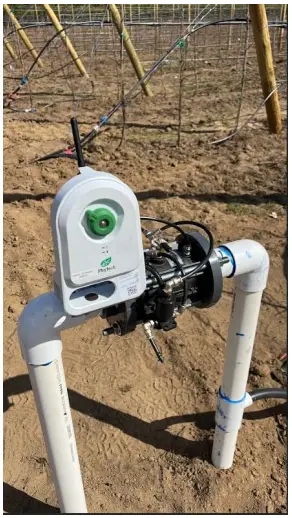 Figure 3 VCU
1.1 Additional materials
- Metal pole – 4-6 m
- PVC 1” riser , 1m length
- 18 V solar panel
- 12 V rechargeable battery
- 12V 2A DC power supply
Installation
Note: High-current electrical installation shall be done only by certified personnel
2.2 GW HW installation
- Thread the cable through the PVC pipe
- Connect the PVC pipe to the CCU.
- Mount PVC pipe to long metal pole
- Mount CCU on pole
- Mount CBU on metal pole
- Mount solar panel (optional) on pole 2-3 m above ground level, facing south.
2.3 CCU-CBU wiring and power
2.3.1 CCU-CBU wiring
Connect the wires from the CCU to the CBU according to Figure 1 port index J12

2.3.2 Power wiring
Connect solar panel/ DC power cable to J1 board connector accordingly (Figure 2)
 2.3.3 Back up battery connection
Connect Back up battery to J3 (Figure 3)

2.3.4 Basic system tests
- Press the system reset button
- Wait for all 3 LED’s on the CBU board of the “ CCU status” to turn on (Figure 4)

Check the phytech App for additional CBU parameter information
The gateway is now connected to the Phytech network and is available for pairing remote VCU’s (for installation of VCU refer to section 4)
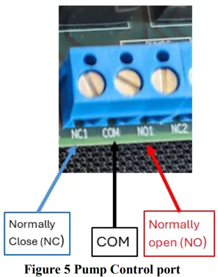
2.4 Pump and Sensor wiring
2.4.1 Pump control wiring
Connect the control pump relay to the J9 port up to 2 pumps (Figure 5).
2.4.2 Dry contact input
Connect dry contact for pump status to port J7 (Figure 6).

2.4.3 Mainline solenoid
The main line solenoid is to be connected to J14 according to Figure 7.
Solenoid specification: Latch/ pulse solenoid 9-12 V range.

2.4.4 Analogue sensors wiring
Analog 4-20 mA sensors can be ired to ports J4 ,J5,J6,J15 and J16 according to Figure 8
 2.4.5 Pulse counter input
Flowmeter with a pulse output can be wired to J8 port up to 2 probes.
For the flowmeter without power connect according to Figure 9
 Flowmeters that require 12V Power can be connected according to Figure 10

VCU installation
Phytech VCU should be installed after the Phytech GWA has been already installed in the field.
- Mount phytech VCU near the field valve
- Connect the built in solenoid to the field valve,
- Turn on the VCU
- Red blinking – searching for Phytech Gateway
- Red light constant – connected to phytech Gateway

FCC Statements
This device complies with Part 15 of the FCC Rules. Operation is subject to the following two conditions:
(1) This device may not cause harmful interference, and (2) This device must accept any interference received, including interference that may cause undesired operation.
Changes or modifications not expressly approved by the party responsible for compliance could void the user’s authority to operate this equipment.
Note: This equipment has been tested and found to comply with the limits for a Class B digital device, pursuant to part 15 of the FCC Rules. These limits are designed to provide reasonable protection against harmful interference in a residential installation. This equipment generates, uses and can radiate radio frequency energy and, if not installed and used in accordance with the instructions, may cause harmful interference to radio communications. However, there is no guarantee that interference will not occur in a particular installation. If this equipment does cause harmful interference to radio or television reception, which can be determined by turning the equipment off and on, the user is encouraged to try to correct the interference by one or more of the following measures:
— Reorient or relocate the receiving antenna.
— Increase the separation between the equipment and receiver.
— Connect the equipment into an outlet on a circuit different from that to which the receiver is connected.
— Consult the dealer or an experienced radio/TV technician for help.
WARNING – RF EXPOSURE COMPLIANCE: This equipment should be installed and operated with a minimum distance 20cm
between the radiator and your body.
-This Class B digital apparatus complies with Canadian ICES-003.
-Cet appareil numerique de la classe B est conforme a la norme NMB-003 du Canada.
♦ IC Statements
This device contains licence-exempt transmitter(s)/receiver(s) that comply with Innovation, Science and Economic Development
Canada’s licence-exempt RSS(s). Operation is subject to the following two conditions:
- This device may not cause interference.
- This device must accept any interference, including interference that may cause undesired operation of the device.
Documents / Resources
 |
Phytech Phytech Irrigation Control System [pdf] User Manual VCU, GW, CCU, Phytech Irrigation Control System, Irrigation Control System, Control System, System |