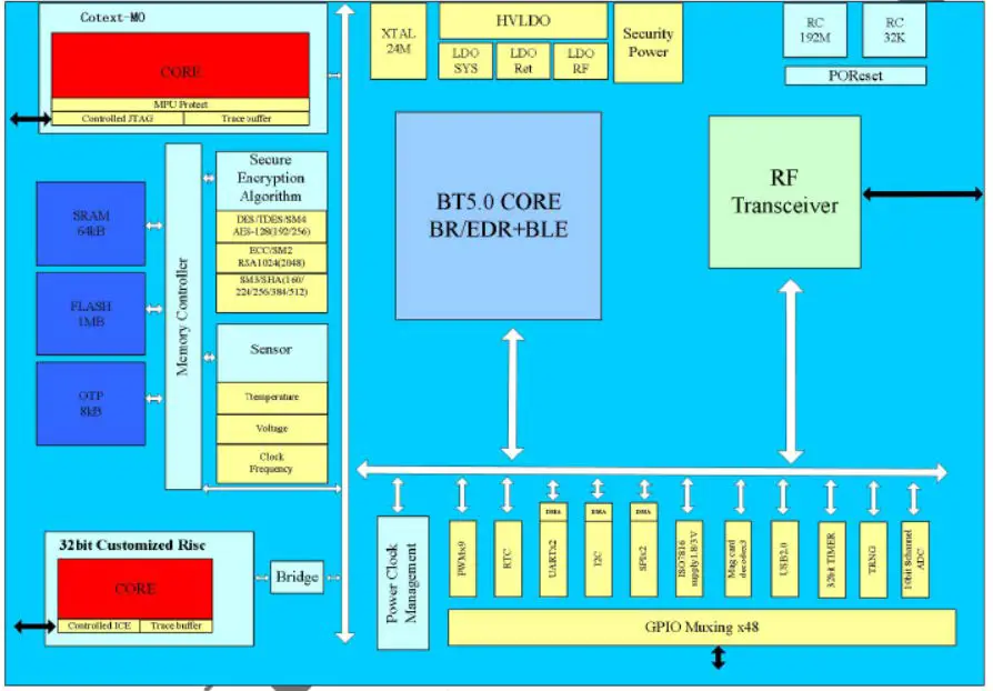
niu C21 Embeds Flash Module

Specifications
- Model: C21 V1.0
- Manufacturer: Beijing Niu Technology Co., Ltd.
Key features
General features
- Single-end RFIO
- -93dBm in BLE mode
- support 250kbps, 1/2/3Mbps data rates
- Tx Power upto +6dBm
- frequency band:2400MHz-2483.5MHz
- Operating temperature:-20~75C
Flash features
C21 module embeds Flash with features below:
- 64K SRAM
- 1MB Flash
- 8KB OTP
Pin layout

BOTTOM view
Pin functions
| No | Pin Name | Description | Multiple Function |
| 1 | GPIO21 | max driver current 20mA | IIC, UART0~1, SPI0~1, PWM0~8 |
| 2 | GPIO22 | max driver current 20mA | IIC, UART0~1, SPI0~1, PWM0~8 |
| 3 | GPIO26 | max driver current 20mA | IIC, UART0~1, SPI0~1, PWM0~8 |
| 4 | GPIO27 | max driver current 20mA | IIC, UART0~1, SPI0~1, PWM0~8 |
| 5 | GPIO28 | max driver current 20mA | IIC, UART0~1, SPI0~1, PWM0~8 |
| 6 | GPIO30 | max driver current 20mA | IIC, UART0~1, SPI0~1, PWM0~8 |
| 7 | GPIO32 | max driver current 100mA | IIC, UART0~1, SPI0~1, PWM0~8 |
| 8 | GPIO33 | ICE default, max driver current 100mA | IIC, UART0~1, SPI0~1, PWM0~8 |
| 9 | GPIO35 | max driver current 100mA | IIC, UART0~1, SPI0~1, PWM0~8 |
| 10 | GPIO36 | max driver current 100mA | IIC, UART0~1, SPI0~1, PWM0~8 |
| 11 | GPIO37 | max driver current 100mA,
adc_channel1 |
IIC, UART0~1, SPI0~1, PWM0~8 |
| 12 | GPIO38 | max driver current 100mA,
adc_channel2 |
IIC, UART0~1, SPI0~1, PWM0~8 |
| 13 | GPIO39 | max driver current 100mA,
adc_channel3 |
IIC, UART0~1, SPI0~1, PWM0~8 |
| 14 | GPIO40 | max driver current 100mA,
adc_channel4 |
IIC, UART0~1, SPI0~1, PWM0~8 |
| 15 | GPIO41 | max driver current 100mA,
adc_channel5 |
IIC, UART0~1, SPI0~1, PWM0~8 |
| 16 | GPIO43 | max driver current 100mA,
adc_channel7 |
IIC, UART0~1, SPI0~1, PWM0~8 |
| 17 | RST | RESET | |
| 18 | BT_3.3V | Input power | |
| 19 | GND | ||
| 20 | RF | RF port | |
| 21 | GND | ||
| 22 | URX | URX | |
| 23 | UTX | UTX | |
| 24 | GPIO2 | max driver current 100mA | IIC, UART0~1, SPI0~1, PWM0~8 |
| 25 | GPIO4 | max driver current 100mA | IIC, UART0~1, SPI0~1, PWM0~8 |
| 26 | GPIO5 | max driver current 100mA | IIC, UART0~1, SPI0~1, PWM0~8 |
| 27 | GPIO6 | max driver current 100mA | IIC, UART0~1, SPI0~1, PWM0~8 |
| 28 | GPIO7 | max driver current 100mA | IIC, UART0~1, SPI0~1, PWM0~8 |
| 29 | GPIO8 | max driver current 20mA | IIC, UART0~1, SPI0~1, PWM0~8 |
| 30 | GPIO9 | max driver current 20mA | IIC, UART0~1, SPI0~1, PWM0~8 |
| 31 | GPIO11 | max driver current 20mA | IIC, UART0~1, SPI0~1, PWM0~8 |
| 32 | GPIO12 | max driver current 20mA | IIC, UART0~1, SPI0~1, PWM0~8 |
| 33 | GPIO13 | max driver current 20mA | IIC, UART0~1, SPI0~1, PWM0~8 |
| 34 | 3.3V | Internal 3.3V | |
| 35 | GPIO14 | max driver current 20mA | IIC, UART0~1, SPI0~1, PWM0~8 |
| 36 | GPIO15 | max driver current 20mA | IIC, UART0~1, SPI0~1, PWM0~8 |
| 37 | GPIO18 | max driver current 20mA | IIC, UART0~1, SPI0~1, PWM0~8 |
| 38 | GPIO17 | max driver current 20mA | IIC, UART0~1, SPI0~1, PWM0~8 |
| 39 | GPIO16 | max driver current 20mA | IIC, UART0~1, SPI0~1, PWM0~8 |
| 40 | GPIO10 | max driver current 20mA | IIC, UART0~1, SPI0~1, PWM0~8 |
| 41 | GND | ||
| 42 | GPIO31 | max driver current 20mA | IIC, UART0~1, SPI0~1, PWM0~8 |
| 43 | GPIO29 | max driver current 20mA | IIC, UART0~1, SPI0~1, PWM0~8 |
| 44 | GND | ||
| 45 | GPIO3 | max driver current 100mA | IIC, UART0~1, SPI0~1, PWM0~8 |
| 46 | BT_3.3V | Input power | |
| 47 | GPIO34 | max driver current 100mA | IIC, UART0~1, SPI0~1, PWM0~8 |
| 48 | GPIO42 | max driver current 100mA,
adc_channel6 |
IIC, UART0~1, SPI0~1, PWM0~8 |
| 49 | GPIO44 | max driver current 100mA,
adc_channel8 |
IIC, UART0~1, SPI0~1, PWM0~8 |
| 50 | GND | ||
| 51 | GND |
Schematic

Size
16(mm)*14(mm)*2.8(mm)
Antenna requirements
The antenna gain is no more than 0.55 dBi.
FCC CAUTION
FCC MODULAR APPROVAL INFORMATION EXAMPLES for Manual
This device complies with Part 15 of the FCC Rules. Operation is subject to the following two conditions:
- This device may not cause harmful interference.
- This device must accept any interference received, including interference that may cause undesired operation.
CAUTION: Changes or modifications not expressly approved by the party responsible for compliance could void the user’s authority to operate the equipment.
NOTE: This equipment has been tested and found to comply with the limits for a Class B digital device, pursuant to Part 15 of the FCC Rules. These limits are designed to provide reasonable protection against harmful interference in a residential installation. This equipment generates uses and can radiate radio frequency energy and, if not installed and used in accordance with the instructions, may cause harmful interference to radio communications. However, there is no guarantee that interference will not occur in a particular installation. If this equipment does cause harmful interference to radio or television reception, which can be determined by turning the equipment off and on, the user is encouraged to try to correct the interference by one or more of the following measures:
- Reorient or relocate the receiving antenna.
- Increase the separation between the equipment and receiver.
- Connect the equipment into an outlet on a circuit different from that to which the receiver is connected.
- Consult the dealer or an experienced radio/TV technician for help.
FCC Radiation Exposure Statement:
This equipment complies with FCC radiation exposure limits set forth for an uncontrolled environment. This equipment should be installed and operated with minimum distance 20cm between the radiator & your body.
OEM INTEGRATION INSTRUCTIONS:
This device is intended only for OEM integrators under the following conditions: The module must be installed in the host equipment such that 20 cm is maintained between the antenna and users, and the transmitter module may not be co-located with any other transmitter or antenna. The module shall be only used with the internal on-board antenna that has been originally tested and certified with this module. External antennas are not supported. As long as these 3 conditions above are met, further transmitter test will not be required.
However, the OEM integrator is still responsible for testing their end-product for any additional compliance requirements required with this module installed (for example, digital device emissions, PC peripheral requirements, etc.). The end-product may need Verification testing, Declaration of Conformity testing, a Permissive Class II Change or new Certification. Please involve a FCC certification specialist in order to determine what will be exactly applicable for the end-product.
Validity of using the module certification:
In the event that these conditions cannot be met (for example certain laptop configurations or co-location with another transmitter), then the FCC authorization for this module in combination with the host equipment is no longer considered valid and the FCC ID of the module cannot be used on the final product. In these circumstances, the OEM integrator will be responsible for re-evaluating the end product (including the transmitter) and obtaining a separate FCC authorization. In such cases, please involve a FCC certification specialist in order to determine if a Permissive Class II Change or new Certification is required.
Upgrade Firmware:
The software provided for firmware upgrade will not be capable to affect any RF parameters as certified for the FCC for this module, in order to prevent compliance issues.
End product labeling:
This transmitter module is authorized only for use in device where the antenna may be installed such that 20 cm may be maintained between the antenna and users. The final end product must be labeled in a visible area with the following: “Contains FCC ID: 2AZ6G-C21”.
Information that must be placed in the end user manual:
The OEM integrator has to be aware not to provide information to the end user regarding how to install or remove this RF module in the user’s manual of the end product which integrates this module. The end user manual shall include all required regulatory information/warning as show in this manual.
“CAUTION: Exposure to Radio Frequency Radiation.
Antenna shall be mounted in such a manner to minimize the potential for human contact during normal operation. The antenna should not be contacted during operation to avoid the possibility of exceeding the FCC radio frequency exposure limit.
Frequently Asked Questions (FAQ)
- Q: What is the operating temperature range of the C21 module?
A: The operating temperature range of the C21 module is -20 to 75 degrees Celsius. - Q: What is the flash capacity of the C21 module?
A: The C21 module embeds a flash with a capacity of 1MB.
Documents / Resources
 |
niu C21 Embeds Flash Module [pdf] Owner's Manual 2AZ6G-C21, 2AZ6GC21, C21 Embeds Flash Module, C21, Embeds Flash Module, Flash Module, Module |


