MuRata LBEE5XV2EA Wi-Fi Plus Bluetooth Module
Specifications
- Design Name: Type 2EA
- P/N: LBEE5XV2EA-802
- Chipset: Infineon CYW55573
- Wireless Standards: 802.11a/b/g/n/ac/ax 2×2 MIMO + Bluetooth 5.3
- Host Interfaces: PCIe 3.0 Gen2, SDIO 3.0 for WLAN; HCI UART, PCM, I2S for Bluetooth
About This Document
Murata’s Type 2EA is a small and high-performance module based on Infineon’s CYW55573 combo chipset, supporting IEEE 802.11a/b/g/n/ac/ax 2×2 MIMO + Bluetooth 5.3 BR/EDR/LE. This application note provides RF and hardware design guidance. Refer to Type 2EA Datasheet for module specification.
Audience & Purpose
Intended audience includes any customer looking to integrate this module into their product. In particular, RF, hardware, systems, and software engineers.
Document Conventions
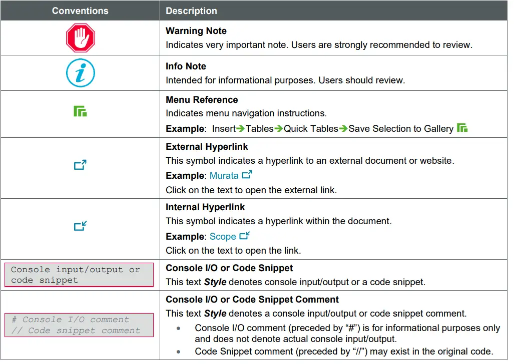
Table 1 describes the document conventions.
Table 1: Document Conventions
Scope
This application note provides detailed information on schematic/layout design, and references RF performance benchmarks. Refer to Type 2EA Datasheet for module specification.
Module Introduction
Type 2EA is a small and high-performance module based on Infineon CYW55573 combo chipset which supports IEEE 802.11a/b/g/n/ac/ax 2×2 MIMO + Bluetooth 5.3 up to 1.2 Gbps PHY data rate on Wi-Fi and 3 Mbps PHY data rate on Bluetooth.
The WLAN section supports PCIe 3.0 Gen2 interface, with optional support for SDIO 3.0. The Bluetooth section supports high-speed 4-wire UART interface and PCM for audio data.
The CYW55573 implements sophisticated enhanced collaborative coexistence hardware mechanisms and algorithms, which ensure that WLAN and Bluetooth is optimized for maximum performance.
In IEEE 802.11ax mode, the WLAN operation supports rates of MCS0 – MCS11 in 20 MHz and 40 MHz and 80 MHz channels for data rate up to 1.2 Gbps.
Features
- WLAN 802.11a/b/g/n/ac/ax 2×2 MIMO + Bluetooth Classic and Low Energy (Version 5.3) combo SMD module with Infineon CYW55573
- Small size LGA package with resin molding and metal shielding.
- Host interfaces: PCIe 3.0 Gen2 and SDIO 3.0 for WLAN; HCI UART, PCM, and I2S for Bluetooth.
- WLAN MAC address and BD address are stored in OTP
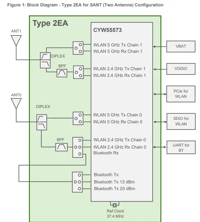
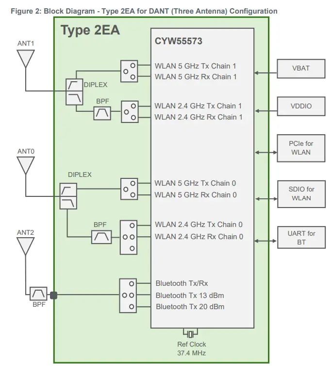
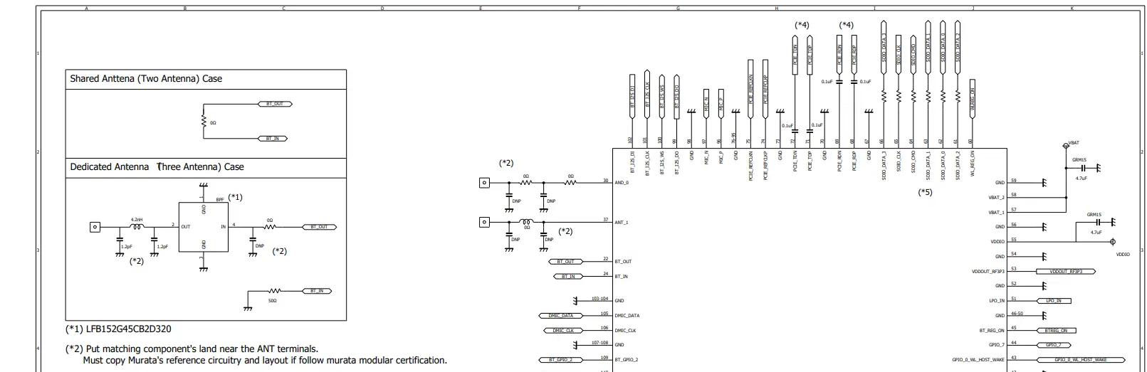
Hardware Block Diagrams
This section shows the difference between the shared-antenna configuration and the dedicated-antenna configuration modules. The key difference is shown in Figure 2. The dedicated-antenna configuration has a dedicated Bluetooth antenna “ANT2”. WLAN has its dedicated antenna “ANT0”. By comparison, the shared-antenna configuration has a single shared WLAN-Bluetooth antenna” ANT0”.
Reference Design
This section details reference schematics which the end user can leverage for designing their own hardware. You can find a detail description of each module pin in module data sheet.
Reference Circuit
Figure 3 shows the u.FL/MHF I connector for Type 2EA module.
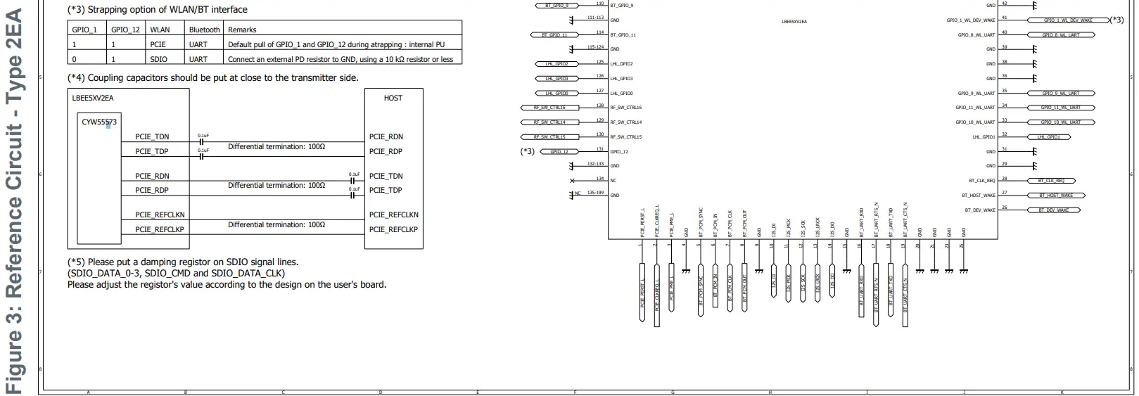
Requirement for High-Speed Digital Signals
- SDIO: SDIO traces should be isometric zero delay routing with 50 Ω impedance.
- Pull-ups in the 10 kΩ to 100 kΩ range are required on the four DATA lines and the CMD line. This requirement must be met during all operating states either through the use of external pull-up resistors or through proper programming of the SDIO host’s internal pull-ups.
- PCIe: TxP/N, RxP/N and CLKP/N signals should be differential 100 Ω impedance. DC blockers are necessary on TxP/N and RxP/N (these should be located very close to the transmission point).
Requirements for Unused Signals
If these signals are not used, no pull-up/down is necessary (floating) for all of GPIOs
3.4 Module Footprint Design
Refer to dimensions in the Type 2EA Datasheet![]() . The DXF File
. The DXF File![]() of module footprint is provided via website.
of module footprint is provided via website.
Recommended Antenna
To use Murata’s regulatory certification, any user must follow below instructions. The DXF File ![]() of the trace is provided via website.
of the trace is provided via website.
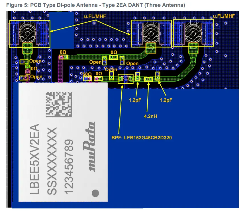
PCB Type Di-pole Antenna with the Co-axial Connector
Users must use recommended antennas. However, user can use any equivalent type of antenna with less antenna gain than antenna gain of recommended antennas for US and EU under approval of Class I Permissive Change by Murata.
Table 2: Cable Options for Antenna Gains
| P/N | Vendor | Form factor | Type | 2.4 GHz Gain | 5 GHz
Gain |
6 GHz
Gain |
Cable Options |
| 219611 | Molex | u.FL/PCB | Di-pole | 2.5 dBi | 3.1 dBi | 3.9dBi | 050, 100, 150, 200, 250 and 300 |
| WT32D1-KX | Unictron | MHF I/PCB | Di-pole | 3.0 dBi | 4.0 dBi | 4.0dBi | 119 |
| W24P-U | Inventek | u.FL/PCB | Di-pole | 3.2 dBi | N/A | N/A | 90 |
If using an antenna vendor that is not listed (Antenova, Pulse, Taoglas, TE, etc.) with the Class I Permissive Change, please evaluate the antenna complies with the technical rules of the FCC KDB 178919 Permissive Change Policy ![]() .
.
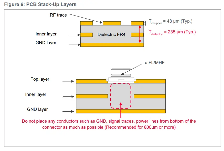
- Users must copy RF trace to u.FL/MHF I connector from the trace layout file provided by Murata in adherence to the guidelines on:
- Trace width accuracy within +/- 0.25 mm.
- Stack height between GND layer and RF trace of 230 ~ 240 µm (Exclude inaccuracy of PCB).
- Passive component location matching Murata design.
- Necessary “Keep out” area around u.FL/MHF I connector.
Figure 4 and Figure 5 shows the PCB type di-pole antennas for Type 2EA module.
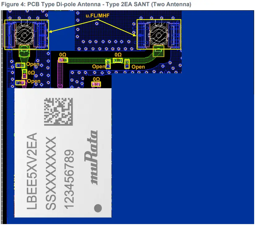
Size: 0603 LQP03 / GRM03 / Resistor
PCB Stack-Up
Figure 6 shows the PCB stack-up layers.
 Setup Configuration Files
To enable Murata’s regulatory certification, below configuration file shall be loaded initially. The transmit power files are hosted at Murata GitHub for Linux .
WLAN Configuration Files for Linux
The files listed in Table 3 shall be used to satisfy regulatory requirements if user wants to use Murata regulatory certification. For more regulatory information, refer to Section 11 of Linux User Guide .
Table 3: WLAN Configuration Files – Linux
| Names | Category | Configuration Files |
| WLAN configuration file | TBD | TBD |
|
WLAN regulatory configuration file |
STA Indoor | cyfmac55572-pcie.clm_blob_STAIndoor |
| STA Outdoor | cyfmac55572-pcie.clm_blob_STAOutdoor | |
| AP Indoor | cyfmac55572-pcie.clm_blob_APIndoor | |
| AP Outdoor | cyfmac55572-pcie.clm_blob_APOutdoor |
The following country codes are defined in “WLAN regulatory configuration file “
• US: United States of America
• CA: Canada
• DE: Europe
• JP: Japan
When you use these fille, please rename them as below.
– WLAN configuration file : “cyfmac55572-pcie.txt” or “cyfmac55572-sdio.txt”
– WLAN regulatory configuration file : “cyfmac55572-pcie.clm_blob” or ““cyfmac55572-sdio.clm_blob”
Bluetooth Configuration Files for Linux
Bluetooth Tx power configuration script files shall be loaded after Bluetooth device initialization. The files listed in Table 4 shall be used to satisfy regulatory requirements if user wants to use Murata regulatory certification.
Table 4: Bluetooth Configuration Files – Linux
| Country | Category | Configuration Files |
| USA / Canada | Shared Bluetooth Antenna | CYW55560A1_001.002.087.0269.0100.FCC.2EA.sAnt.hcd |
| USA / Canada | Dedicated Bluetooth Antenna | CYW55560A1_001.002.087.0269.0103.FCC.2EA.dAnt.hcd |
| Europe / Japan | Shared Bluetooth Antenna | CYW55560A1_001.002.087.0269.0106.EU.JP.2EA.sAnt.hcd |
| Europe / Japan | Dedicated Bluetooth Antenna | CYW55560A1_001.002.087.0269.0107.EU.JP.2EA.dAnt.hcd |
Reference Performance Data
This section describes the reference performance data.
Typical Rx Minimum Sensitivity Level at Module Antenna port
This section describes the Typical Rx Minimum Sensitivity Level at module antenna port for WLAN and Bluetooth.
WLAN
- Conditions
- VBAT = 3.3V, VDDIO = 1.8V
- FW version: 18.53.157.2
Table 5 describe the typical Rx minimum sensitivity level at module antenna port for WLAN at 2.4 GHz for 20 MHz bandwidth. Table 6, Table 7 and Table 8 describe the typical Rx minimum sensitivity level at module antenna port for WLAN at 5 GHz for 20 MHz, 40 MHz and 80 MHz bandwidth. Table 9, Table 10 and Table 11 describe the typical Rx minimum sensitivity level at module antenna port for WLAN 6GHz for 20 MHz, 40 MHz and 80 MHz bandwidth.
Table 5: Rx Minimum Sensitivity Level – WLAN at 2.4 GHz (20 MHz)
|
Frequency |
Rx Minimum Sensitivity Level [dBm] | |||||||
| in MHz | 11b | 11g | 11n (HT 20) | 11ax (HE 20) | ||||
| 1 Mbps | 11 Mbps | 6 Mbps | 54 Mbps | MCS0 | MCS7 | MCS0 | MCS11 | |
| 2412 | -97 | -89 | -94 | -76 | -93 | -75 | -93 | -63 |
| 2442 | -97 | -89 | -94 | -76 | -93 | -75 | -93 | -63 |
| 2472 | -97 | -89 | -94 | -76 | -93 | -75 | -93 | -63 |
Table 6: Rx Minimum Sensitivity Level – WLAN at 5 GHz (20 MHz)
|
Frequency in MHz |
Rx Minimum Sensitivity Level [dBm] | |||||||
| 11a | 11n (HT 20) | 11ac (VHT 20) | 11ax (HE 20) | |||||
| 6 Mbps | 54 Mbps | MCS0 | MCS7 | MCS0 | MCS8 | MCS0 | MCS11 | |
| 5180 | -93 | -75 | -93 | -73 | -93 | -69 | -93 | -62 |
| 5500 | -93 | -75 | -93 | -73 | -93 | -69 | -93 | -62 |
| 5825 | -93 | -75 | -93 | -73 | -93 | -69 | -93 | -62 |
Table 7: Rx Minimum Sensitivity Level – WLAN at 5 GHz (40 MHz)
|
Frequency in MHz |
Rx Minimum Sensitivity Level [dBm] | |||||
| 11n (HT 40) | 11ac (VHT 40) | 11ax (HE 40) | ||||
| MCS0 | MCS7 | MCS0 | MCS9 | MCS0 | MCS11 | |
| 5190 | -90 | -70 | -90 | -64 | -91 | -59 |
| 5510 | -90 | -70 | -90 | -64 | -91 | -59 |
| 5795 | -90 | -70 | -90 | -64 | -91 | -59 |
Table 8: Rx Minimum Sensitivity Level – WLAN at 5 GHz (80 MHz)
|
Frequency in MHz |
Rx Minimum Sensitivity Level [dBm] | |||
| 11ac (VHT 80) | 11ax (HE 80) | |||
| MCS0 | MCS9 | MCS0 | MCS11 | |
| 5210 | -87 | -62 | -88 | -56 |
| 5530 | -87 | -62 | -88 | -56 |
| 5775 | -87 | -62 | -88 | -56 |
Table 9: Rx Minimum Sensitivity Level – WLAN at 6 GHz (20MHz)
|
Frequency in MHz |
Rx Minimum Sensitivity Level [dBm] | |||
| 11a | 11ax (HE 20) | |||
| 6 Mbps | MCS0 | MCS11 | ||
| 5955 | -94 | -94 | -62 | |
| 6515 | -92 | -92 | -61 | |
| 7115 | -90 | -90 | -59 | |
|
Table 10: Rx |
Minimum Sensitivity Level – WLAN at 6 GHz (40MHz) |
|||
|
Frequency in MHz |
Rx Minimum Sensitivity Level [dBm] | |||
| 11ax (HE 40) | ||||
| MCS0 | MCS11 | |||
| 5965 | -92 | -59 | ||
| 6525 | -90 | -57 | ||
| 7085 | -89 | -56 | ||
|
Table 11: Rx |
Minimum Sensitivity Level – WLAN at 6 GHz (80MHz) |
|||
|
Frequency in MHz |
Rx Minimum Sensitivity Level [dBm] | |||
| 11ax (HE 80) | ||||
| MCS0 | MCS11 | |||
| 5985 | -89 | -57 | ||
| 6545 | -87 | -55 | ||
| 7025 | -86 | -54 | ||
Bluetooth
- Conditions
- VBAT = 3.3V, VDDIO = 1.8V
- Hcd file: CYW55560A1_001.002.087.0159.0008_wlcsp_iPA_sLNA.hcd
Table 12 describes the typical Rx minimum sensitivity level for Bluetooth.
Table 12: Rx Minimum Sensitivity Level – Bluetooth
| Frequency in MHz | Rx Minimum Sensitivity Level[dBm] | ||||||
| DH5 | 2DH5 | 3DH5 | LE 125K | LE 500K | LE 1M | LE 2M | |
| 2402 | -91 | -94 | -88 | -108 | -102 | -96 | -93 |
| 2441 | -91 | -94 | -88 | -108 | -102 | -96 | -93 |
| 2480 | -91 | -94 | -88 | -108 | -102 | -96 | -93 |
Typical Tx/Rx Current Consumption
This section describes the typical Tx/Rx current consumption for WLAN and Bluetooth.
WLAN
- Conditions
- VBAT = 3.3V, VDDIO = 1.8V
- FW version: 18.53.157.2
- Current definition
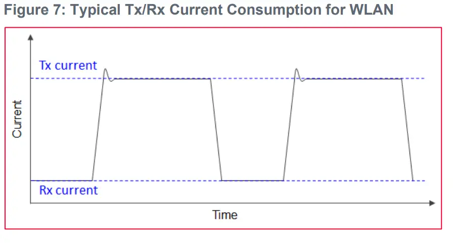
Table 13: Typical Tx/Rx Current Consumption – WLAN at 2.4 GHz (1SS)
| Mode | Data Rate | Setting Tx Power [dBm] | Current [mA] | |
| Tx | Rx | |||
| VBAT | VBAT | |||
| 11b | 1 Mbps | 18 | 290 | 40 |
| 11g | 6 Mbps | 17 | 280 | 40 |
| 11n (HT20) | MCS0 | 17 | 280 | 40 |
| 11ax (HE20) | MCS0 | 14 | 230 | 40 |
Table 14: Typical Tx/Rx Current Consumption – WLAN at 2.4 GHz (2SS)
| Mode | Data Rate | Setting Tx Power [dBm] | Current [mA] | |
| Tx | Rx | |||
| VBAT | VBAT | |||
| 11n (HT20) | MCS8 | 13 | 370 | 55 |
| 11ax (HE20) | MCS0 | 11 | 330 | 55 |
Table 15 and Table 16 describes the typical Tx/Rx current consumption for WLAN at 5 GHz.
Table 15: Typical Tx/Rx Current Consumption – WLAN at 5 GHz (1SS)
| Mode | Data Rate | Setting Tx Power [dBm] | Current [mA] | |
| Tx | Rx | |||
| VBAT | VBAT | |||
| 11a | 6 Mbps | 16 | 400 | 50 |
| 11n (HT20) | MCS0 | 14 | 360 | 50 |
| 11ac (VHT20) | MCS0 | 14 | 360 | 50 |
| 11ax (HE20) | MCS0 | 12 | 330 | 50 |
| 11n (HT40) | MCS0 | 14 | 380 | 55 |
| 11ac (VHT40) | MCS0 | 14 | 380 | 55 |
| 11ax (HE40) | MCS0 | 12 | 340 | 55 |
| 11ac (VHT80) | MCS0 | 14 | 390 | 65 |
| 11ax (HE80) | MCS0 | 12 | 370 | 65 |
Table 16: Typical Tx/Rx Current Consumption – WLAN at 5 GHz (2SS)
| Mode | Data Rate | Setting Tx Power [dBm] | Current [mA] | |
| Tx | Rx | |||
| VBAT | VBAT | |||
| 11n (HT20) | MCS8 | 11 | 580 | 65 |
| 11ac (VHT20) | MCS0 | 11 | 580 | 65 |
| 11ax (HE20) | MCS0 | 9 | 520 | 65 |
| 11n (HT40) | MCS8 | 11 | 600 | 75 |
| 11ac (VHT40) | MCS0 | 11 | 560 | 75 |
| 11ax (HE40) | MCS0 | 9 | 540 | 75 |
| 11ac (VHT80) | MCS0 | 11 | 620 | 90 |
| 11ax (HE80) | MCS0 | 9 | 570 | 90 |
Table 17 and Table 18 describes the typical Tx/Rx current consumption for WLAN at 6 GHz.
Table 17: Typical Tx/Rx Current Consumption – WLAN at 6 GHz (1SS)
| Mode | Data Rate | Setting Tx Power [dBm] | Current [mA] | |
| Tx | Rx | |||
| VBAT | VBAT | |||
| 11a | 6Mbps | 12 | 240 | 45 |
| 11ax (HE20) | MCS0 | 12 | 350 | 45 |
| 11ax (HE40) | MCS0 | 12 | 350 | 55 |
| 11ax (HE80) | MCS0 | 12 | 360 | 60 |
Table 18: Typical Tx/Rx Current Consumption – WLAN at 6 GHz (2SS)
| Mode | Data Rate | Setting Tx Power [dBm] | Current [mA] | |
| Tx | Rx | |||
| VBAT | VBAT | |||
| 11ax (HE20) | MCS0 | 9 | 530 | 65 |
| 11ax (HE40) | MCS0 | 9 | 540 | 80 |
| 11ax (HE80) | MCS0 | 9 | 550 | 90 |
Bluetooth
- Conditions
- VBAT = 3.3V, VDDIO = 1.8V
- Hcd file: CYW55560A1_001.002.087.0159.0008_wlcsp_iPA_sLNA.hcd
- Current definition
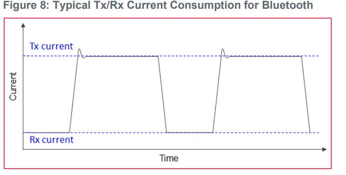
Table 19 describes the typical Tx/Rx current consumption for Bluetooth.
Table 19: Typical Tx/Rx Current Consumption – Bluetooth at 2.4 GHz
| Mode | Setting Tx Power [dBm] | Current [mA] | |
| Tx | Rx | ||
| VBAT | VBAT | ||
| BR (1DH5) | 8 | 25 | 11 |
| EDR (3DH5) | 4 | 25 | 11 |
| LE 125K | 8 | 25 | 11 |
| LE 500K | 8 | 25 | 11 |
| LE 1M | 8 | 25 | 11 |
| LE 2M | 8 | 25 | 11 |
Typical Sleep Current Consumption
This section describes the typical sleep current consumption for Wi-Fi and Bluetooth.
WLAN
- Conditions
- VBAT = 3.3V, VDDIO = 1.8V
- WL_REG_ON: ON, BT_REG_ON: OFF
- Platform: BRIX
- Combo FW: 18.53.180.7
- WLAN I/F: PCIe
- Beacon Interval = 100 ms
Table 20 describes the typical sleep current consumption for WLAN.
Table 20: Typical Sleep Current Consumption – WLAN
| Band | Mode | Current consumption VBAT [mA] |
| – | Chip deep sleep (L1.2) | 0.1 |
| 2.4 GHz | IEEE Power Save: DTIM1 | 2.28 |
| IEEE Power Save: DTIM3 | 0.85 | |
| IEEE Power Save: DTIM5 | 0.55 | |
| 5 GHz | IEEE Power Save: DTIM1 | 1.15 |
| IEEE Power Save: DTIM3 | 0.45 | |
| IEEE Power Save: DTIM5 | 0.31 | |
| 6 GHz | IEEE Power Save: DTIM1 | 1.15 |
| IEEE Power Save: DTIM3 | 0.44 | |
| IEEE Power Save: DTIM5 | 0.30 |
Bluetooth
- Conditions
- VBAT = 3.3V, VDDIO = 1.8V
- WL_REG_ON: OFF, BT_REG_ON: ON
- Platform: Windows PC/CyBluetool
- Hcd file: CYW55560A1_001.002.087.0159.0017_wlcsp_iPA_dLNA_Murata_Type2EA.hcd
- Bluetooth I/F: UART
Table 21 describes the typical sleep current consumption for Bluetooth.
Table 21: Typical Sleep Current Consumption – Bluetooth
| Mode | Current consumption VBAT [uA] |
| Deep Sleep (BT Only) | 37 |
| BT Page Scan 1.28 s | 112 |
| BT Page & Inquiry Scan 1.28 s | 146 |
| BT Master Sniff mode 500 ms | 70 |
| Advertise 1.28 s | 45 |
| BLE Scan 1.28 s | 108 |
| LE Link Master 1 s | 58 |
Throughput
This section describes the typical and concurrent throughput communications.
Typical Throughput PCIe Interface
The typical throughput test configurations are:
- VBAT = 3.3V, VDDIO = 1.8V
- Platform: Embedded Artists iMX8M Mini uCOM
- Combo FW: 18.53.212.8
- WLAN I/F: PCIe
- Access Point: AXE11000 (NETGEAR)
- Distance between Access Point and the Target is around 3 ft.
- UDP commands︓Bit rate was set at more than 20% of observed corresponding TCP throughput.
Sample UDP command:
- iperf3 <server-ip-addr> -u -b <20%-of-TCP>M -P1 -t 60
Table 22 shows the typical throughput data for the modules.
Table 22: WLAN Typical Throughput Data – PCIe
| Mode | TCP Throughput in Mbps | UDP Throughput in Mbps | ||
| Tx | Rx | Tx | Rx | |
| 2.4 GHz 11ax HE20 MIMO | 237 | 235 | 250 | 251 |
| 5 GHz 11ax HE80 MIMO | 787 | 638 | 800 | 919 |
| 6 GHz 11ax HE80 MIMO | 747 | 600 | 836 | 891 |
Typical Throughput SDIO Interface
The typical throughput test configurations are:
- VBAT = 3.3V, VDDIO = 1.8V
- Platform: NXP IMX8M-EVKB
- Combo FW: 18.53.212.8
- WLAN I/F: SDIO
- Access Point: AXE11000 (NETGEAR)
- Distance between Access Point and the Target is around 3 ft.
- UDP commands︓Bit rate was set at more than 20% of observed corresponding TCP throughput.
Sample UDP command:
iperf3 <server-ip-addr> -u -b <20%-of-TCP>M -P1 -t 60
Table 23 shows the typical throughput data for the modules.
Table 23: WLAN Typical Throughput Data – SDIO
| Mode | TCP Throughput in Mbps | UDP Throughput in Mbps | ||
| Tx | Rx | Tx | Rx | |
| 2.4 GHz 11ax HE20 MIMO | 227 | 218 | 236 | 235 |
| 5 GHz 11ax HE80 MIMO | 389 | 366 | 493 | 503 |
| 6 GHz 11ax HE80 MIMO | 389 | 370 | 493 | 500 |
References
Table 24 reviews all the key reference documents that the user may like to refer to.
Table 24: Reference Table
| Support Site | Notes |
| Murata Type 2EA Module Datasheet | Murata Type 2EA module datasheet (TYPE2EA.pdf) |
| Murata Type 2EA Module Footprint | Murata Type 2EA module footprint (type2ea-module-footprint- topview.dxf) |
| Murata Type 2EA PCB Type Di-pole Antenna | Murata Type 2EA module trace antenna (type2EA_Di-pole-and- Trace-Antenna.dxf) |
| Linux WLAN Configuration | Murata GitHub link for Linux NVRAM file for 2EA |
| Linux WLAN Regulatory Configuration | Murata GitHub link for Linux CLM_BLOB file for 2EA |
| Linux Bluetooth Configuration | Murata GitHub link for Linux HCD files for 2EA |
| Linux User Guide | Murata Linux User Guide for Infineon modules (Murata Wi-Fi & BT (IFX) Solution for i.MX Linux User Guide.pdf). Murata website to be updated soon. |
In case Murata website does not have the updated document, please refer to the Connectivity Module page on the Murata Community Forum. This contains a pinned post with all the updated documents.
Technical Support Contacts
Table 25 lists all the support resources available for the Murata Wi-Fi/BT solution.
Table 25: List of Support Resources
| Support Site | Notes |
| Murata Community Forum | Primary support point for technical queries. This is an open forum for all customers. Registration is required. |
| Murata i.MX Landing Page | No login credentials required. Murata documentation covering hardware, software, testing, etc. is provided here. |
| Landing page for uSD-M.2 Adapter. In conjunction with Murata i.MX Landing Page, this should provide the user with comprehensive getting started documentation. | |
| Murata Module Landing Page | No login credentials required. Murata documentation covering all Infineon-based Wi-Fi/BT modules is provided here. |
Revision History
| Revision | Date | Change | Change Description |
| 1.0 | Jul 26, 2023 | First Issue | |
| 2.0 | Mar 27, 2025 | 3.1 Reference Circuit | Added a damping resistor on SDIO lines. |
| 3.5.1 PCB Type Di-pole Antenna with the Co- axial Connector | Modified Table2 Form factor Removed 206994
Added 50ohm on BT_IN line at Figure 5 |
||
| 3.5.3 PCB Stack-Up | Modify the wording: Underneath of u.FL/MHF connector. | ||
| 4.1 WLAN Configuration Files for Linux | Added WLAN regulatory configuration file | ||
| 4.2 Bluetooth configuration files | Added Bluetooth configuration files. | ||
| 6. Reference | Added a link for module footprint / Antenna / Configuration files / Linux / Linux User Guide |
Copyright © Murata Manufacturing Co., Ltd. All rights reserved. The information and content in this document are provided “as-is” with no warranties of any kind and are for informational purpose only. Data and information have been carefully checked and are believed to be accurate; however, no liability or responsibility for any errors, omissions, or inaccuracies is assumed.
The Bluetooth® word mark and logos are registered trademarks owned by Bluetooth SIG, Inc. Other brand and product names are trademarks or registered trademarks of their respective owners.
Specifications are subject to change without notice.
©2023 by Murata Manufacturing Co., Ltd.
- Mar 27, 2025
- E2B-09-1413
- Rev. 2.0
- www.murata.com
FAQ
- Q: What is the purpose of the Type 2EA module?
A: The Type 2EA module is designed for customers looking to integrate Wi-Fi and Bluetooth connectivity into their products. - Q: What are the host interfaces supported by the module?
A: The module supports PCIe 3.0 Gen2, SDIO 3.0 for WLAN; HCI UART, PCM, and I2S for Bluetooth.
Documents / Resources
 |
MuRata LBEE5XV2EA Wi-Fi Plus Bluetooth Module [pdf] User Guide LBEE5XV2EA Wi-Fi Plus Bluetooth Module, LBEE5XV2EA, Wi-Fi Plus Bluetooth Module, Plus Bluetooth Module, Bluetooth Module |