MOXA 4510 Series Advanced Controllers

Introduction
Package Checklist
- 1 x ioThinx 4510 Series product
- 1 x quick installation guide (printed)
- 2 x side cover plate
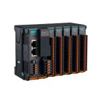
Appearance

Installation
Connecting the System Power
Wire Range: 12 to 16 AWG (ferrule diameter: 2.053 to 1.291 mm)
Wire Strip Length: 10 mm
Connect your 12 to 48 VDC power source to the terminal block SP+ and SP- terminals on the ioThinx 4510. The ground connector of the system is on the back of the unit, which will connect to the DIN rail when the product is attached to it.

![]() WARNING
WARNING
- Cables rated at minimum 120°C must be used for the power supply terminal.
- Terminal blocks should not have more than one conductor connected per clamping point.
Connecting Field Power
Wire Range: 12 to 16 AWG (ferrule diameter: 2.053 to 1.291 mm)
Wire Strip Length: 10 mm
The ioThinx 4510 can receive field power through a 12/24 VDC power input. Field power can be used to supply power for some I/O modules, such as digital input and analog output modules.

Connecting the Field Power Ground
Wire Range: AWG 12 to 18 (ferrule diameter 2.053 to 1.024 mm)
Wire Strip Length: 10 mm
The iothinx 4510 has a field power ground and two ground pins on the back of the device.
For surge protection, connect the Field Ground pin (![]() ) to your field power ground and connect the DIN rail to the earth ground.
) to your field power ground and connect the DIN rail to the earth ground.

Connecting To The Network
Ethernet Communication
The ioThinx 4510 is equipped with dual unmanaged LAN ports (RJ45).
Connect a network Ethernet cable to either port to provide an Ethernet connection to the unit.
Serial Communication
The ioThinx 4510 is equipped with a 3-in-1 serial interface, which supports 1 RS-232 port, or 1 RS-422 port, or 2 RS-485 ports. Refer to the pin assignment table below to set up serial connections to the unit.

| PIN | RS-232 (P1) | RS-422 (P1) | RS-485 (P1/P2) |
| 1 | TXD | TXD+ | DATA 1+ |
| 2 | RXD | TXD- | DATA 1- |
| 3 | RTS | RXD+ | DATA 2+ |
| 4 | CTS | RXD- | DATA 2- |
| 5 | GND | GND | GND |
Wire Range: AWG 16 to 28 (ferrule diameter: 1.291 to 0.321 mm),
Wire Strip Length: 10 mm
45M Module Wiring
For detailed 45M module wiring, refer to the ioThinx 4510 User’s Manual on Moxa’s official website.
Installing the System on a DIN Rail
Step 1: Hook the mounting clip of the unit onto the DIN rail and lower the clip onto the DIN rail. Reserve at least 5.5 cm of space above the DIN rail to ensure that there is enough room to install the unit.

Step 2: Push the unit toward the DIN rail until the mounting clip snaps in place.

Installing a 45M Module on a DIN Rail
Step 1: Align the 45M module side by side with the head/CPU module, making sure that the upper and lower rails are hooked together.

Step 2: Align the 45M module side by side with the head/CPU module and then push the 45M module until it touches the DIN rail. Next, apply more force until the module clips on to the DIN rail.

NOTE
After the module is firmly attached to the DIN rail, the module connections to the internal bus will be established.
NOTE
The maximum number installing on the ioThinx 4510 for 45MR modules is 32 pcs and that does not support 45ML modules.
For information on the use of the 45MR module with ioThinx 4533, please refer to this website (https://iothinxcalculator.moxa.com/). If the website is invalid, be sure to contact MOXA to confirm product installation.
Removing a 45M Module from a DIN Rail
Step 1: Use your finger to lift the release tab on the lower part of the module.

Step 2: Push the top of the release tab to latch it, and then pull the module out.

NOTE
Electrical connections for the internal bus will be disconnected when removing the 45M module.
![]() WARNING
WARNING
Be sure the power is off before removing modules to avoid damaging the equipment.
Installing the Covers on the First and Last Module
Attach the covers to the first and last module to cover the modules’ contacts.

![]() NOTICE
NOTICE
Be sure to attach the covers to provide electrostatic discharge protection.
Horizontal Installation
Before installing the device, make sure there is enough space between the device and nearby items (walls and other devices/equipment) to ensure proper heat dissipation.
To ensure that the device works properly, we suggest reserving the amount of space indicated in the adjacent figure.

![]() CAUTION
CAUTION
DO NOT install the device vertically. If the device is installed vertically, the fanless heat dissipation design will not perform as intended.
LED Indicators
| Name | Indication | LED Qty | Description |
| SP | System Power | 1 | On: Power on Off: Power off |
| FP | Field Power | 1 | On: Power on Off: Power off |
| RDY | System (Kernel) Ready | 1 | Green: System ready Green Slow Blinking: Booting up Red: System error Red Slow Blinking: Loading Factory Default Recovery/Upgrading firmware/Backup mode Red Fast Blinking: Safe mode Off: Power off |
| LAN | Ethernet Connection | 1 for each port | Green: 100Mb connection Amber: 10Mb connection Blinking: Data transmitting Off: Disconnected |
| Px | Serial Connection | 1 for each port | Green: Tx Amber: Rx Non-simultaneous Blinking: Data transmitting Off: Disconnected |
System Configuration
- Configuration via Web Console
Main configuration of the unit is done through the web console.- Default IP Address: 192.168.127.254
- Subnet Mask: 255.255.255.0
NOTE Be sure to configure the host PC’s IP address to use the same subnet as the unit. For example, 192.168.127.253
- IOxpress Utility
IOxpress is a utility that helps users with mass deployment of, searching for, and locating units on the local network. This utility can be downloaded from Moxa’s website. - Loading the Factory Default Settings
There are three ways to restore the unit to the factory default settings:
a. Hold the Reset button inside the front door of the unit for 10 seconds while it is powered on.
b. Select the unit from the IOxpress utility’s Device Library page, and then choose Load Factory Default.
c. Go to the System tab on the unit’s web console and choose Load Factory Default in the Configuration section.
NOTE Please refer to the user’s manual for information on detailed configuration and settings.
Downloading Software Packages
Related software packages can be downloaded from the Moxa website.
Step 1: Go to the following address: https://www.moxa.com/en/support
Step 2: Type the model name in the search box or select a product from the drop-down box and then click Search. The ioThinx 4500 Series is used for the examples below.

Step 3: Go to the Software page to download the latest software for the product.

Specifications
| Input Current | System Power: 0.8 A @ 12 VDC Field Power: 2 A (max.) |
| Input Voltage | 12 to 48 VDC Field Power: 12/24 VDC |
| Operating Temperature | Standard Models: -20 to 60°C (-4 to 140°F) Wide Temp. Models: -40 to 75°C (-40 to 167°F) |
| Storage Temperature | -40 to 85°C (-40 to 185°F) |
Hazardous Locations Information
![]() II 3G Ex ec IIC T4 Gc UL 20 ATEX 2412X
II 3G Ex ec IIC T4 Gc UL 20 ATEX 2412X
Standards Covered:
EN IEC 60079-0:2018
EN IEC 60079-7:2015 + A1:2018
Conductors suitable for rated cable temperature ≥ 120°C
Ambient Range:
-40°C ≤ Tamb ≤ 75°C (-T models)
-20°C ≤ Tamb ≤ 60°C (standard models)
Rated Cable Temp ≥ 120°C
Address of the Manufacturer:
Moxa Inc.
No. 1111, Heping Rd., Bade Dist., Taoyuan City 334004, Taiwan
![]() ATTENTION
ATTENTION
These devices are open-type devices that are to be installed in an enclosure only accessible with the use of a tool, suitable for the environment.
This equipment is suitable for use in Class I, Division 2, Groups A, B, C, and D or nonhazardous locations only.
![]() WARNING—EXPLOSION HAZARD
WARNING—EXPLOSION HAZARD
Do not disconnect the equipment unless the power has been removed or the area is known to be nonhazardous. Substitution of any components may impair suitability for Class I, Division 2.
![]() WARNING
WARNING
The Debug port and Console port are FOR MAINTENANCE ONLY; NOT FOR USE IN HAZARDOUS LOCATIONS
Conditions for Safe Use
- This device is only for indoor use in environments with pollution degree 2, as defined in EN IEC 60664-1.
- The equipment shall be installed in an enclosure that provides a minimum ingress protection of IP54, in accordance with EN IEC 60079-0.
- If the equipment is used in a manner not specified by the manufacturer, the protection provided by the equipment may be impaired. The manufacturer is not responsible for accidents caused by improper use of the equipment.
![]()
Documents / Resources
 |
MOXA 4510 Series Advanced Controllers [pdf] Installation Guide 4510 Series Advanced Controllers, 4510 Series, Advanced Controllers, Controllers |