Milesight EM400-MUD Multi Functional Ultrasonic Distance Sensor

Specifications
- Product Name: Multifunctional Ultrasonic Distance Sensor
- Model: EM400-MUD
- Waterproof Rating: IP67
- Operating Modes: Standard, Trash Bin, Parking Lot
- Additional Sensors: 3-axis accelerometer, temperature sensor
- Communication: Milesight IoT Cloud compatible
Product Usage Instructions
Safety Precautions
It is essential to follow the safety precautions to ensure proper operation and longevity of the device:
- Do not disassemble or remodel the device.
- Change the default password (123456) for security purposes during initial configuration.
- Avoid placing the device near naked flames or in extreme temperatures.
- Ensure both batteries are new when installing to maximize battery life.
- Avoid subjecting the device to shocks or impacts.
Declaration of Conformity
The EM400-MUD complies with CE, FCC, and RoHS requirements. Any unauthorized copying of information in this guide is prohibited.
Contact Information
For technical support, contact Milesight at:
- Email: iot.support@milesight.com
- Support Portal: support.milesight-iot.com
- Telephone: 86-592-5085280
Revision History
Refer to the revision history for updates and version information.
Frequently Asked Questions (FAQ)
- Q: Can the EM400-MUD be used indoors?
- A: While the device is suitable for outdoor applications, it can also be used indoors depending on the specific use case.
- Q: How do I change the operating mode of the sensor?
- A: To change the operating mode, refer to the Operation Guide section in the user manual for detailed instructions on selecting between standard, trash bin, and parking lot modes.
Multifunctional Ultrasonic
Distance Sensor
EM400-MUD
User Guide
Safety Precautions
Milesight will not shoulder responsibility for any loss or damage resulting from not following the instructions of this operating guide.
- The device must not be disassembled or remodeled in any way.
- In order to protect the security of the device, please change the device password when first configuration. Default password is 123456.
- The device is not intended to be used as a reference sensor, and Milesight won’t should responsibility for any damage which may result from inaccurate readings.
- Do not place the device close to objects with naked flames.
- Do not place the device in where the temperature is below/above the operating range.
- Make sure both batteries are newest when install, or battery life will be reduced.
- The device must never be subjected to shocks or impacts.
Declaration of Conformity
EM400-MUD is in conformity with the essential requirements and other relevant provisions of the CE, FCC, and RoHS.

Copyright © 2011-2023 Milesight. All rights reserved.
All information in this guide is protected by copyright law. Whereby, no organization or individual shall copy or reproduce the whole or part of this user guide by any means without written authorization from Xiamen Milesight IoT Co., Ltd.

For assistance, please contact
Milesight technical support
- Email: iot.support@milesight.com
- Support Portal: support.milesight-iot.com
- Tel: 86-592-5085280
- Fax: 86-592-5023065
- Address: Building C09, Software Park III, Xiamen 361024, China
Revision History
| Date | Doc Version | Description |
| March 30, 2023 | V 1.0 | Initial version |
| June 15, 2023 | V 1.1 | Add EM400-MUD NB/Cat M Version |
Product Introduction
Overview
EM400-MUD is a multifunctional ultrasonic distance sensor with small blind spot. Besides a wide measuring rage, EM400-MUD is equipped with three pre-set modes including standard mode, trash bin mode, and parking lot mode for different applications.
With IP67 waterproof rating and internal damp-proof coating, it is suitable for outdoor applications. Besides, EM400-MUD is equipped with a 3-axis accelerometer and temperature sensor to detect the tilt status of devices. Compliant with Milesight IoT Cloud, users know the container status and fill-in level in real-time via browser and mobile App remotely.
Features
- 3-450 cm wide detection range with small blind zone
- Equipped with three pre-set modes for different applications
- Equipped with NTC thermistor for the detection and alarm of trash burning
- Built-in 3-axis accelerometer sensor to monitor device tilt status
- Damp-proof coating inside and IP67 waterproof enclosure for outdoor applications
- Built-in two 9000 mAh replaceable batteries and work for 10 years without replacement
- Equipped with NFC for one touch configuration, support card emulation mode
- Equipped with GNSS positioning (NB version only)
- Function well with standard LoRaWAN® gateways and network servers (LoRaWAN® version only)
- Compatible with Milesight IoT Cloud (LoRaWAN® version only)
Hardware Introduction
Packing List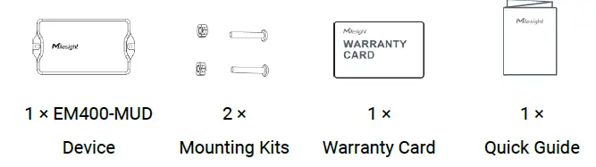
If any of the above items is missing or damaged, please contact your sales representative.
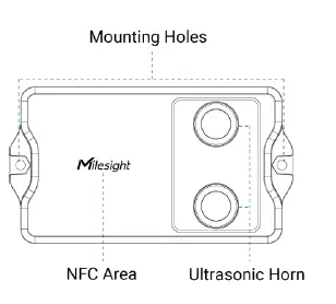
Hardware Overview
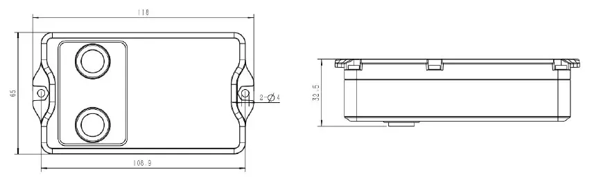
Dimensions (mm)
Power Button
EM400-MUD can be switched on/off via NFC. Besides, users can use power button to switch on/off and reset the device manually.
| Function | Action | LED Indication |
| Switch On | Press and hold the button for more than 3 seconds. | Off → On |
| Switch Off | Press and hold the button for more than 3 seconds. | On → Off |
| Reset | Press and hold the button for more than 10 seconds. | Quickly Blinks |
| Check
On/Off Status |
Quickly press the power button. | Light On: Device is on |
| Light Off: Device is off |
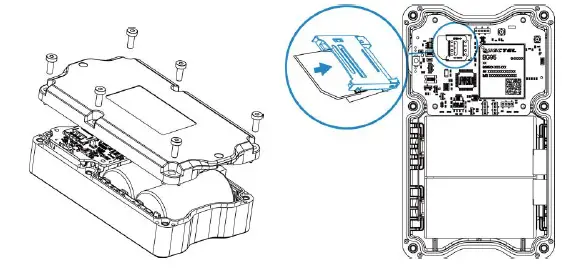
SIM Installation (NB Version Only)
Release the screws and back cover, insert the SIM card (3FF), then replace the back cover to the device and fix the screws.
Note
- PSM (Power Saving Mode) is required for the SIM card.
- The device does not support hot plugging (also called hot swapping), please reboot the device after inserting the SIM card.
- When a new SIM card is inserted to the device for the first time, it will take about 2 minutes to register to network; next time the registration time will be shorten to 30s.
- When the device does not send data, the device will go to sleep mode and the network status will be unregistered.
Operation Guide
NFC Configuration
EM400-MUD can be configured via NFC.
- Download and install “Milesight ToolBox” App from Google Play or App Store.
- Enable NFC on the smartphone and open “Milesight ToolBox” App.
- Attach the smartphone with NFC area to the device to read the basic information.
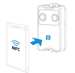
- Basic information and settings of devices will be shown on ToolBox if it’s recognized successfully. You can switch on/off, read and write the device by tapping the button on the Apps. In order to protect the security of devices, password validation is required when configuring via unused phone. Default password is 123456.

Note
- Ensure the location of smartphone NFC area and it’s recommended to take off phone case.
- If the smartphone fails to read/write configurations via NFC, keep the phone away and back to try again.
- EM400-MUD can also be configured by dedicated NFC reader provided by Milesight IoT.
Basic Settings
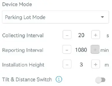
Go to Device > Setting > General Settings of ToolBox App to change the reporting interval, etc.
| Parameters | Description |
| Device Mode | Select from Standard Mode, Bin Mode or Parking Lot Mode. |
| Reporting Interval | Reporting interval of transmitting data to server.
LoRaWAN® Version
|
| occupancy status change, it will report immediately.
NB Version Standard Mode/Bin Mode: 30 minutes as default, range: 1~1440 minutes. |
|
|
Collecting Interval |
Collecting interval of measuring distance on Parking Lot Mode. Default:
20s; Range: 1~600s |
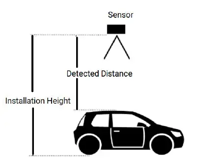
| Installation Height | Set the installation height between device and ground when in Parking Lot Mode. Default: 3m; Range: 0.030~4.500m
Threshold Distance Value (Δ) is 1m as default, triggering logic is as below:
|
| Tilt & Distance
Switch |
When detecting that the offset angle is greater than 20 degrees, turn off the distance sensor. |
| Change Password | Change the password for the ToolBox App or software to access this device. |
| NB Version Only | |
| Cumulative
Numbers |
Store this number of periodic packets to report together. |
| Positioning
Settings |
Enable GNSS positioning. When the device is on motion status, it will only upload positioning data instead of distance data. |
| The duration of
Motion |
When device is detected to move beyond this duration, it will upload a GNSS data packet. |
| The duration of
stationary |
When device is detected to stop moving beyond this duration, it will upload a GNSS data packet. |
| Motion Report
Interval/Min |
The interval to report GNSS data during the motion. |
Communication Settings
LoRaWAN Settings (LoRaWAN® Version Only)
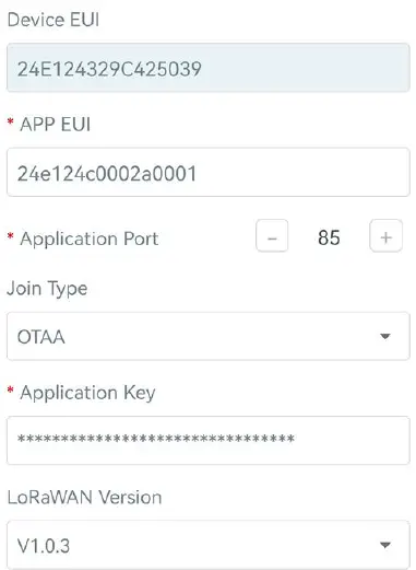
Go to Device > Setting > LoRaWAN Settings of ToolBox App to configure join type, App EUI, App Key and other information. You can also keep all settings by default.
| Parameters | Description |
| Device EUI | Unique ID of the device which can also be found on the label. |
| App EUI | Default App EUI is 24E124C0002A0001. |
| Application Port | The port used for sending and receiving data, default port is 85. |
| Join Type | OTAA and ABP mode are available. |
| Application Key | Appkey for OTAA mode, default is 5572404C696E6B4C6F52613230313823. |
| Device Address | DevAddr for ABP mode, default is the 5th to 12th digits of SN. |
| Network Session
Key |
Nwkskey for ABP mode, default is 5572404C696E6B4C6F52613230313823. |
| Application
Session Key |
Appskey for ABP mode, default is 5572404C696E6B4C6F52613230313823. |
| LoRaWAN Version | V1.0.2, V1.0.3 are available. |
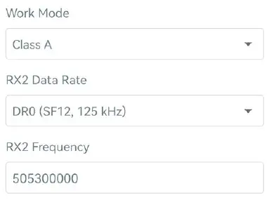
| Work Mode | It’s fixed as Class A. |
| RX2 Data Rate | RX2 data rate to receive downlinks. |
| RX2 Frequency | RX2 frequency to receive downlinks. Unit: Hz |
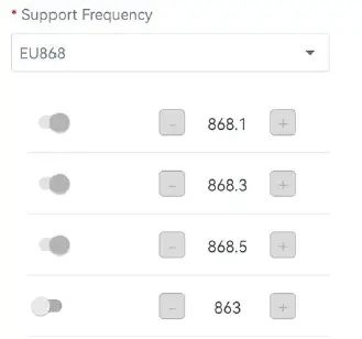
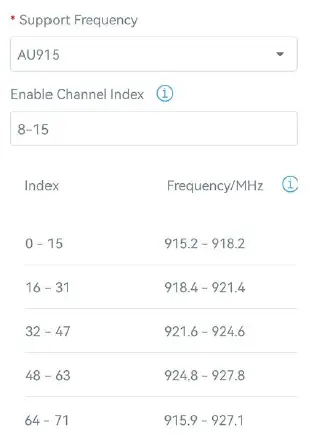
| Channel | Enable or disable the frequency to send uplinks. |
If frequency is one of CN470/AU915/US915, enter the index of the channel that you want to enable and make them separated by commas. Examples
|
|
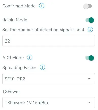
| Spread Factor | If ADR is disabled, the device will send data via this spread factor. |
| Confirmed Mode | If the device does not receive ACK packet from network server, it will resend data once. |
| Rejoin Mode | Reporting interval ≤ 35 mins: the device will send a specific number of LinkCheckReq MAC packets to the network server every reporting interval or 2*reporting interval to validate connectivity; If there is no response, the device will re-join the network.
Reporting interval > 35 mins: the device will send a specific number of |
| LinkCheckReq MAC packets to the network server every reporting interval to
validate connectivity; If there is no response, the device will re-join the network. |
|
| Set the number of
packets sent |
When rejoin mode is enabled, set the number of LinkCheckReq packets sent.
Note: the actual sending number is Set the number of packets sent + 1. |
| ADR Mode | Allow network server to adjust datarate of the device. |
| Tx Power | Transmit power of device. |
Note
- Please contact sales for device EUI list if there are many units.
- Please contact sales if you need random App keys before purchase.
- Select OTAA mode if you use Milesight IoT cloud to manage devices.
- Only OTAA mode supports rejoin mode.
Application Mode Settings (NB Version Only)
Go to Device > Setting > Application Mode Settings of ToolBox App to configure the application mode and server information.
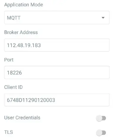
| Parameters | Description |
| Application Mode | Select from AWS, TCP, UDP, and MQTT. |
| AWS | |
| Server Address | Fill in the AWS server domain name which the data sends to. |
| CA File | Import the CA.crt file. |
| Client Certificate | Import the client certificate. |
| Client Key | Import the client key. |
| TCP/UDP | |
| Server Address | Fill in the TCP/UDP server address (IP/domain name). |
| Server Port | Fill in the TCP/UDP server port. Range: 1-65535. |
| MQTT | |
| Broker Address | Fill in MQTT broker address to receive data. |
| Port | Fill in MQTT broker port to receive data. |
| Client ID | Client ID is the unique identity of the client to the server, it must be unique
when all clients are connected to the same server. |
User Credentials
| Enable | Enable user credentials. |
| Username | The username used for connecting to MQTT broker. |
| Password | The password used for connecting to MQTT broker. |
TLS
| Enable | Enable the TLS encryption in MQTT communication. |
| Protocol | It’s fixed as TLS v1.2. |
| CA File | Import the CA.crt file. |
| Client Certificate | Import the client certificate. |
| Client Key | Import the client key. |
Advanced Settings
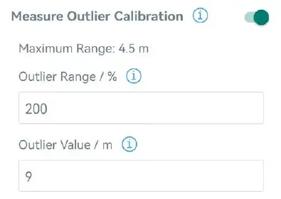
Calibration Settings
Go to Device > Setting > Calibration Settings to enable calibration. EM400-MUD supports two calibration types.
- Numerical Calibration: users can define calibration value to correct every distance.

- Measure Outlier Calibration: users can define either outlier range or value When the device distance value exceeds the outlier range (or range) comparing to last value, the device will measure the distance again.
Threshold Settings
Go to Device > Setting > Threshold Settings to enable the threshold settings and input the distance threshold. EM400-MUD will detect whether the distance reaches the threshold according to collecting interval. If threshold is triggered, it uploads the current data once instantly.
Note: threshold setting is only for bin mode and standard mode.

| Parameters | Description |
| Collecting Interval | Collecting interval to detect distance, this should be smaller than or equal to reporting interval. |
| Threshold Dismiss Report | When the collected value changes from outside the threshold to within the threshold, a threshold release packet will be reported. |
Maintenance
Upgrade
- Download firmware from Milesight website to your smartphone.
- Open Toolbox App, go to Device > Maintenance and click Browse to import firmware and upgrade the device.
Note
- Operation on ToolBox is not supported during a firmware upgrade.
- Only Android version ToolBox supports the upgrade feature.

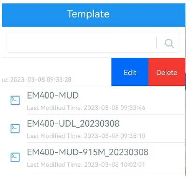
Backup
EM400-MUD supports configuration backup for easy and quick device configuration in bulk. Backup is allowed only for devices with the same model and frequency band.
- Go to Template page on the App and save current settings as a template. You can also edit the template file.
- Select one template file which saved in the smartphone and click Write, then attach to another device to write configuration.

Note: Slide the template item left to edit or delete the template. Click the template to edit the configurations.
Reset to Factory Default
Please select one of following methods to reset device:
- Via Hardware: Hold on power button (internal) for more than 10s.
- Via ToolBox App: Go to Device > Maintenance to click Reset, then attach smartphone with NFC area to device to complete reset.


Installation
- Drill two holes on the container cover according to the location of device mounting holes.
- Put the device under container cover and align the holes in order to perfectly screw the bolts into the holes from the other side of the cover.

Besides, the device can also be fixed by two M4 mounting screws and wall plugs.

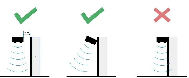
Installation location
- In order to provide the best data transmission, please ensure the device is deployed within the signal range of the LoRaWAN® gateway or base station and keep it away from metal objects and obstacles.
- The device must be placed in a horizontal position above the detected object so that it has a clear path to the object.
- The device should be installed at least 30cm away from the side-wall without obstructions blocking the ultrasonic signal. If the device needs to be installed on the side wall, please ensure the ultrasonic horn is away from the side wall.
- When EM400-MUD is in waste bin mode, place the device in the center of waste bin mode and here are some recommended sizes of waste bins: when the height is 88cm, the minimum radius should be 24cm.
Communication Protocol
For decoder examples please find files on https://github.com/Milesight-IoT/SensorDecoders .
LoRaWAN® Version
All data are based on following format (HEX), the Data field should follow little-endian
| Channel1 | Type1 | Data1 | Channel2 | Type2 | Data2 | Channel 3 | … |
| 1 Byte | 1 Byte | N Bytes | 1 Byte | 1 Byte | M Bytes | 1 Byte | … |
Uplink Data
| Channel | Type | Description |
| ff | 01(Protocol Version) | 01=>V1 |
| 09 (Hardware Version) | 01 40 => V1.4 | |
| 0a (Software Version) | 01 14 => V1.14 | |
| 0b (Power On) | Device is on | |
| 0f (Device Type) | 00: Class A, 01: Class B, 02: Class C | |
| 16 (Device SN) | 16 digits | |
| 01 | 75(Battery Level) | UINT8, Unit: % |
| 03 | 67 (Temperature) | INT16, Unit: °C |
| 04 | 82 (Distance) | INT16, Unit: mm |
| 05 | 00 (Device Position) | 00: Normal (horizontal offset angle < 20°) 01: Tilt (horizontal offset angle ≥ 20°) |
| 83 | 67(Temperature) | Temperature (2 Bytes) + Alarm Status(1 Byte)
Temperature: unit — °C Alarm Status:
|
| 84 | 82(Distance) | Distance (2 Bytes) + Alarm Status (1 Byte) Distance: unit — mm
Alarm Status
|
Examples
Device information: report once whenever join the network.
| ff0bff ff0101 ff166329c42503920003 ff090100 ff0a0101 ff0f00 | |||||
| Channel | Type | Value | Channel | Type | Value |
| ff | 0b
(Power On) |
ff
(Reserved) |
ff | 01
(Protocol Version) |
01 (V1) |
| Channel | Type | Value | Channel | Type | Value |
| ff | 16
(Device SN) |
6329c425
03920003 |
ff | 09
(Hardware version) |
0100
(V1.0) |
| Channel | Type | Value | Channel | Type | Value |
| ff | 0a(Software
version) |
0101
(V1.1) |
ff | 0f
(Device Type) |
00
(Class A) |
Periodic uplink: report according to reporting interval.
| 017564 0367f800 04820101 050000 | |||||
| Channel | Type | Value | Channel | Type | Value |
| 01 | 75
(Battery) |
64 => 100% | 03 | 67
(Temperature) |
f8 00 => 00 f8
= 248 * 0.1 =24.8 °C |
| Channel | Type | Value | Channel | Type | Value |
| 04 | 82
(Distance) |
01 01 =>
01 01 =257mm =0.257m |
05 | 00
(Device Position) |
00=Normal |
Distance Threshold: report when distance reaches the threshold or returns back to normal value.
| 8482330701 | ||
| Channel | Type | Value |
| 84 | 82
(Distance) |
Distance: 33 07 =>07 33 = 1843mm = 1.843m
Alarm Status: 01= Alarm |
Temperature Threshold: report when the abrupt change of temperature is greater than 5 °C.
| 8367220101 | ||
| Channel | Type | Value |
| 83 | 67
(Temperature) |
Temperature: 22 01 =>01 22 = 290 * 0.1 = 29°C
Alarm Status: 01= Alarm |
Downlink Commands
EM400-MUD supports downlink commands to configure the device. Application port is 85 by default.
| Channel | Type | Description |
| ff | 10 (Reboot) | ff (Reserved) |
| 03 (Set Reporting Interval) | 2 Bytes, unit: s | |
| 71 (Set Device Mode) | 00 = Standard Mode; 01 = Bin Mode; 02 = Parking Lot Mode | |
| 3e (Set Tilt & Distance Switch) | 00 = Disable; 01 = Enable | |
| 56 (Set Ultrasonic Distance
Sensor) |
00 = Disable; 01 = Enable | |
| 06 (Set Threshold Alarm) | 9 Bytes, CTRL(1B)+Min(2B)+Max(2B)+00000000(4B)
CTRL: |
| Bit2~Bit0
00- disable 001-below 010-above 011-within below or above Bit5~Bit3: 01- Standard Mode 010-Bin Mode Bit6=0 Bit7: 0 – disable threshold dismiss report 1 – enable threshold dismiss report |
||
| 70 (Set Height Threshold in
Parking Lot Mode) |
2 Bytes, unit: mm | |
| 77 (Set Installation Height) | 2 Bytes, unit: mm |
Example
Set reporting interval as 20 minutes.
| ff03b004 | ||
| Channel | Type | Value |
| ff | 03 (Set Reporting Interval) | b0 04 => 04 b0 = 1200s = 20 minutes |
Reboot the device.
| ff10ff | ||
| Channel | Type | Value |
| ff | 10 (Reboot) | ff (Reserved) |
Set the device as standard mode.
| ff7100 | ||
| Channel | Type | Value |
| ff | 71 (Set Device Mode) | 00 = Standard Mode |
Enable “Tilt & Distance Switch” feature.
| ff3e01 | ||
| Channel | Type | Value |
| ff | 3e (Set Tilt & Distance Switch) | 01 = Enable |
When the distance is below 20cm or above 80cm, the sensor will send threshold alarm.
| ff3e 8c c800 2003 0000 0000 | ||
| Channel | Type | Value |
| ff | 06 (Set Threshold Alarm) | CTRL: cc=10 001 100
100=below or above 001=standard mode 10=enable threshold dismiss report Min: c8 00 => 00 c8 = 200 mm = 20 cm Max: 2003 => 03 20 = 800 mm = 80cm |
Set the height threshold in parking lot mode as 0.03m.
| ff701e00 | ||
| Channel | Type | Value |
| ff | 70 (Set Height Threshold in
Parking Lot Mode) |
1e 00 => 00 1e =30mm =0.03m |
Set the installation height as 4.5m.
| ff779411 | ||
| Channel | Type | Value |
| ff | 77 (Set Installation Height) | 94 11 => 11 94 =4500mm =4.5m |
NB Version
AWS/MQTT Topics
When the device is connected to AWS/MQTT server, the bi-directional communication uses different topics.
| Topic | Content |
| em/[SN]/status | Receive periodic reports, threshold alarms, etc. |
| em/[SN]/cmd/update | Send downlink commands |
| em/[SN]/cmd/update/accepted | Receive success ACK of downlink commands
Note: users need to send downlink command to enable ACK feature first. |
Uplink Data
All data are based on following format (HEX)
| Start | ID | Packet
Length |
FLAG | Frame
Counter |
Protocol
Version |
Software
Version |
Hardwar
e Version |
| 02 | 0001 | 2 Bytes | 00 | 0000 | 01 | 4 Bytes | 4 Bytes |
| SN | IMEI | IMSI | ICCID | Signal | Data Length | Data1 | … |
| 16
Bytes |
15
Bytes |
15
Bytes |
20
Bytes |
1 Byte | 2 Bytes | N Bytes | .. |
Example
| 02 0001 005f 00 0000 01 30313031 30313030
36373438443131323930313230303033 383638353038303631393234353133 343630303833383833383036363836 3839383630346238313032326330343536363836 10 000E 01750103677D000482FDFF050000 |
|
| Type | Content |
| Start | 02 |
| ID | 0001 |
| Packet Length | 00 5f=95 bytes |
| FLAG | 00 |
| Frame Counter | 0000 |
| Protocol Version | 01=V1 |
| Software Version | 30 31 30 31 => 0101=V1.1 |
| Hardware Version | 30 31 30 30 => 0100=V1.0 |
| SN | 36 37 34 38 44 31 31 32 39 30 31 32 30 30 30
33=>6748d11290120003 |
| IMEI | 38 36 38 35 30 38 30 36 31 39 32 34 35 31 33
=>868508061924513 |
| IMSI | 34 36 30 30 38 33 38 38 33 38 30 36 36 38 36 =>
460083883806686 |
| ICCID | 38 39 38 36 30 34 62 38 31 30 32 32 63 30 34 35 36 36
38 36 => 898604b81022c0456686 |
| Network Signal | 10=>16 asu |
| Data Length | 0e=>14 Bytes |
| Data | See details below |
Data part is based on Channel+Type+Data, the Data field should follow little-endian
| Channel | Type | Description |
| 01 | 75(Battery Level) | UINT8, Unit: % |
| 03 | 67 (Temperature) | INT16, Unit: °C |
| 04 | 82 (Distance) | INT16, Unit: mm |
| 05 | 00 (Device Position) | 00: Normal (horizontal offset angle < 20°)
01: Tilt (horizontal offset angle ≥ 20°) |
| 06 | 88 (Location) | Byte 1-4: latitude*1000000
Byte 5-8: longitude*1000000 Byte 9: motion status, 20=unknown, 21=start moving, 22=in motion, 23=stop moving Note: If the device fails to get GNSS data, the latitude or longitude will show FFFFFFFF. |
| 83 | 67(Temperature) | Temperature (2 Bytes) + Alarm Status(1 Byte)
Temperature: unit — °C Alarm Status: 00 -Alarm dismiss 01 -Alarm |
| 84 | 82(Distance) | Distance (2 Bytes) + Alarm Status (1 Byte) Distance: unit — mm
Alarm Status: 00 -Alarm dismiss 01 -Alarm |
Examples
Periodic uplink: report according to reporting interval*cumulative numbers (30 mins*12 by default) when the device is stationary.
| 017564 0367f800 04820101 050000 | |||||
| Channel | Type | Value | Channel | Type | Value |
| 01 | 75
(Battery) |
64 => 100% | 03 | 67
(Temperature) |
f8 00 => 00 f8
= 248 * 0.1 =24.8 °C |
| Channel | Type | Value | Channel | Type | Value |
| 04 | 82
(Distance) |
01 01 =>
01 01 =257mm =0.257m |
05 | 00
(Device Position) |
00=Normal |
GNSS uplink: report when positioning setting is enabled and the device is in motion.
| 050001 068873c177019cff080722 | |||||
| Channel | Type | Value | Channel | Type | Value |
| 05 | 00
(Device |
01=Tilt | 06 | 88(Locati
on) |
Latitude: 73c17701=>01 77 c1
73=24625523/1000000=24.62 |
| Position) | 5523
Longitude: 9cff0807=>07 08 ff 9c=118030236/1000000=118. 030236 22=in motion |
Distance Threshold: report when distance reaches the threshold or returns back to normal value. If the threshold triggering time is close to periodic report time, it will send with periodic uplink.
| 8482330701 | ||
| Channel | Type | Value |
| 84 | 82
(Distance) |
Distance: 33 07 =>07 33 = 1843mm = 1.843m
01= Alarm |
Temperature Threshold: report once when the abrupt change of temperature is greater than 5 °C.
| 8367220101 0688FFFFFFFFFFFFFFFF20 | |||||
| Channel | Type | Value | Channel | Type | Value |
| 83 | 67
(Temperatu re) |
Temperature: 22 01
=>01 22 = 290 * 0.1 = 29 °C 01= Alarm |
06 | 88(Locati on) | Latitude/longitude
: FFFFFFFF 20=unknown |
Downlink Commands
EM400-MUD supports downlink commands to configure the device. Note that it can only receive downlink commands within the 10s after sending uplink packets.
| Channel | Type | Description |
| ff | 10 (Reboot) | ff (Reserved) |
| 03 (Reporting Interval) | 4 Bytes, unit: s | |
| 71 (Device Mode) | 00 = Standard Mode; 01 = Bin Mode | |
| 3e (Tilt & Distance Switch) | 00 = Disable; 01 = Enable | |
| a0 (Position Setting) | 00 = Disable; 01 = Enable | |
| 58 (Duration of Motion and Stationary) | 5 Bytes,
Byte 1: duration of motion, unit: s Byte 2-5: duration of stationary, unit: s |
|
| 8e (Motion Report Interval) | 5 Bytes,
Byte 1: 00 = Disable; 01 = Enable Byte 2-5: report interval, unit: s |
| 9e (Cumulative Numbers) | 2 Bytes,
Byte 1: 00 = Disable; 01 = Enable Byte 2: Cumulative numbers |
|
| 9f (ACK of Downlink Command) | 00 = Disable; 01 = Enable | |
| 06 (Set Threshold Alarm) | 9 Bytes,
CTRL(1B)+Min(2B)+Max(2B)+00000000 (4 B) CTRL: Bit2~Bit0: 000-disable 001-below 010-above 011-within 100-below or above Bit5~Bit3: 001-Standard Mode 010-Bin Mode Bit6=0 Bit7: 0 – disable threshold dismiss report 1 – enable threshold dismiss report |
Example
Set reporting interval as 20 minutes.
| ff03b0040000 | ||
| Channel | Type | Value |
| ff | 03 (Set Reporting Interval) | b0 04 00 00 => 00 00 04 b0 = 1200s = 20
minutes |
Reboot the device.
| ff10ff | ||
| Channel | Type | Value |
| ff | 10 (Reboot) | ff (Reserved) |
Set the device as standard mode.
| ff7100 | ||
| Channel | Type | Value |
| ff | 71 (Set Device Mode) | 00 = Standard Mode |
When the distance is below 20cm or above 80cm, the sensor will send threshold alarm.
| ff3e 8c c800 2003 0000 0000 | ||
| Channel | Type | Value |
| ff | 06 (Set Threshold Alarm) | CTRL: cc=10 001 100
100=below or above 001=standard mode 10=enable threshold dismiss report Min: c8 00 => 00 c8 = 200 mm = 20 cm Max: 2003 => 03 20 = 800 mm = 80cm |
Set duration of motion to 50s and duration of stationary to 180s.
| ff5832b4000000 | ||
| Channel | Type | Value |
| ff | 58(Duration of Motion and Stationary) | Duration of motion: 32=50s Duration of stationary: b4 00 00 00=00
00 00 b4=180s |
- Tel: +33 477 92 03 56
- Email : contact@rg2i.com
- www.rg2i.com
- 14 rue Edouard Petit 42000 St-Etienne
Documents / Resources
 |
Milesight EM400-MUD Multi Functional Ultrasonic Distance Sensor [pdf] User Guide EM400-MUD, EM400-MUD NB-Cat M Version, EM400-MUD Multi Functional Ultrasonic Distance Sensor, EM400-MUD Multi Functional Ultrasonic Distance Sensor, EM400-MUD, Multi Functional Ultrasonic Distance Sensor, Functional Ultrasonic Distance Sensor, Ultrasonic Distance Sensor, Distance Sensor, Sensor |


