MegaChips MRF61_FI IEEE 802.11ah Sub-1 GHz Wi-Fi HaLow Module

Product Specifications
- Product Name: MRF61_FI
- Model Name: T/N MFIM0002 MBWM000002 MBWM000024
- Version: 1.1
- Date: 24/01/2025
- Manufacturer: MegaChips Corporation
CAUTION
- Prohibition on copying and disclosure.
These specifications include intellectual property and know-how belonging to MegaChips Corporation (“MCC”) and its partner companies.
Therefore, do not use these specifications for any purpose other than the purpose expressly agreed to by MCC’s customer and MCC.
Also, do not duplicate, copy, or reproduce these specifications, nor reveal these specifications to any third party without MCC’s prior written consent. - No guarantee of rights
MCC does not warrant that it owns or controls any of the information, patents, copyrights or other intellectual property rights contained in these specifications.
MCC grants no license of patents, copyrights or other intellectual property rights contained in these specifications.
MCC disclaims all liability arising from the use of the specifications with regard to infringement of any patents, copyrights or other intellectual property rights. - Safety designs such as redundancy
While MCC has been making continuous effort to enhance the quality and reliability of its devices, the possibility of malfunction cannot be eliminated entirely.
To minimize risk of damage or injury to persons or property arising from a malfunction in a device, customer must incorporate sufficient safety measures in its design, such as redundancy, fire-containment, and anti-failure features.
(If the customer intends to use the devices for applications other than those specified between the customer and MCC, please contact MCC sales representative before such use.) - Restriction on use
MCC provides no warranty relating to the use of the devices, where there is risk of serious damage, environmental pollution, loss of life, injury or damage to property, or where reliability or special quality is essential, such as life support, military use, or space exploration. - Radiation-proof design
This device has not been designed to be radiation-resistant. - Export restriction
The export of this device may be regulated by the government under customs, anti-proliferation rules, or other regulations, and export may be prohibited without governmental license. - No prior notice of revision
These specifications are based on materials dated 02/10/2025, and MCC reserves the right to revise these specifications without any prior notice. For mass production planning, please reference the latest version of the specifications.
Product Overview
Introduction
MegaChips provides a complete Wi-Fi HaLow connectivity solution. The MFIM0002 is a fully integrated Wi-Fi HaLow® modules with long-range, low-power consumption and superior RF performance, featuring the MM6108 Wi-Fi HaLow SoC.
The MFIM0002 are designed in compliance with the IEEE 802.11ah standard, supporting data rates up to 32.5 Mbps with programmable operation between 902 MHz and 928 MHz.
MRF61_FI_FL(T/N : MBWM000002) has U.FL connector and output to U.FL connector.
MRF61_FI_TH(T/N : MBWM000024) does not have U.FL connector and output to Plated Half-hole. Primary Function of ANT pin (pin number 44) is different.
Please see “3.3 Pin Diagram”.
This module includes ultra-long-reach PA, high linearity LNA, T/R switch, 32 MHz crystal oscillator and it has been designed for a simplified Wi-Fi HaLow connection to an external host for applications in which a customer wants to merely replace their prior RF technology with a Wi-Fi HaLow connection while leveraging the latest WPA3 security protocol.
Battery-operated applications are supported by a combination of features which are inherently supported by the module. The IEEE 802.11ah standard provides for extended sleep times for battery-operated Stations (STAs or client devices), with longer durations than other prior IEEE 802.11a/b/g/n/ac generations. It also allows longer extended maximum idle times for clients to conserve energy without being removed from the access point’s (AP’s) list of associated devices.
Features
Table 1-1 Features
| Ultra-long-range, low-power Wi-Fi HaLow module for IoT Applications: | |
| Frequency Band | 920MHz Band(Sub-1GHz Band) |
| Channel Band Width | 1MHz/2MHz/4MHz/8MHz |
| Maximum Transmission power | 20dBm |
| Modulation method | OFDM |
| Sub carrier modulation method
(It is depended on communication conditions) |
BPSK,QPSK,16-QAM,64-QAM |
| Theoretical maximum transmission rate | 32.5Mbps(In case of 8MHz BW,MCS7) |
Applications
For Internet of Things (IoT) and Machine-to-Machine (M2M) applications such as:
- Surveillance Cameras and Sensors
- Cloud Connectivity
- Low-power Sensor Networks
- Building Automation Systems (BAS)
- Asset Tracking and Management
- Machine Performance Monitors & Sensors
- Building Access Control & Security
- Drone Video and Navigation Communications
- Connected Toys and Games
- Rural Internet Access
- Agricultural and Farm Networks
- Utility Smart Meter and Intelligent Grid
- Proximity Sensors
- Industrial Automation Controls
- Smart Home Automation
- EV Car Chargers
- Appliances
- Construction Site Connectivity
- Smart Signs and Kiosks
- Retail Point-of-Sale Terminals
- IP Sensor Networks
- Biometric IDs and Keypads
- Warehouse Connectivity
- Intelligent Lighting Controls
- BT/ZigBee(™)/Z-Wave(™) to Wi-Fi HaLow Gateways
- Wi-Fi to Wi-Fi HaLow Bridges
- Wi-Fi HaLow Client Adapters/Dongles
- Smart City Networks
Product Specifications
Table 2-1 Product Specifications
| Product Specifications | ||
| Power supply | Voltage | VBAT : +3.0~+3.6V VDD_FEM : +3.0~+3.6V
VDDIO : +1.8~+3.6V |
| Maximum power consumption | T.B.D | |
| Maximum Storage temperature | -40℃~+125℃ | |
| Maximum Storage temperature | -40℃~+85℃ | |
| RF
performance |
RF terminal Impedance | 50ohms |
| Frequency range | 902MHz~928MHz | |
| External Dimensions | 23mm x 14mm x 2.58mm | |
| Weight | 2g | |
Channel Frequency
Table 2-2 TX/RX Frequency
| 41Channel
spacing 41(MHz) |
41Channel
center 41frequency index |
41Channel center frequency
41(MHz) |
41Channel center
41frequency index |
41Channel center frequency
41(MHz) |
|
411 |
413 | 41903.5 | 4129 | 41916.5 |
| 415 | 41904.5 | 4131 | 41917.5 | |
| 417 | 41905.5 | 4133 | 41918.5 | |
| 419 | 41906.5 | 4135 | 41919.5 | |
| 4111 | 41907.5 | 4137 | 41920.5 | |
| 4113 | 41908.5 | 4139 | 41921.5 | |
| 4115 | 41909.5 | 4141 | 41922.5 | |
| 4117 | 41910.5 | 4143 | 41923.5 | |
| 4119 | 41911.5 | 4145 | 41924.5 | |
| 4121 | 41912.5 | 4147 | 41925.5 | |
| 4123 | 41913.5 | 4149 | 41926.5 | |
| 4125 | 41914.5 | |||
| 4127 | 41915.5 |
|
412 |
416 | 41905.0 | 4134 | 41919.0 |
| 4110 | 41907.0 | 4138 | 41921.0 | |
| 4114 | 41909.0 | 4142 | 41923.0 | |
| 4118 | 41911.0 | 4146 | 41925.0 | |
| 4122 | 41913.0 | |||
| 4126 | 41915.0 | |||
| 4130 | 41917.0 | |||
|
414 |
418 | 41906.0 | 4132 | 41918.0 |
| 4116 | 41910.0 | 4140 | 41922.0 | |
| 4124 | 41914.0 | 4148 | 41926.0 | |
|
418 |
4112 | 41908.0 | ||
| 4128 | 41916.0 | |||
| 4144 | 41924.0 |
Functional Description
The following sections describe the functions of the MFIM0002 device.
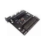
Exterior View

Picture 3-2 MRF61_FI_TH Top view 
Pin Diagram
Table 3-1 Pin Diagram
| 40Pin | 40Name | 40Type | 40Primary Function | 40remarks |
| 401 | 40GND | 40Power | 40Ground | |
| 402 | 40GND | 40Power | 40Ground | |
| 403 | 40GND | 40Power | 40Ground | |
| 404 | 40GND | 40Power | 40Ground | |
| 405 | 40GND | 40Power | 40Ground | |
| 406 | 40GND | 40Power | 40Ground | |
| 407 | 40Reserved | 40I | 40implement a 10kΩ pull- down resistor | |
| 408 | 40Reserved | 40I | 40implement a 10kΩ pull- down resistor | |
| 409 | 40NC | 40NC | 40Do Not Connect | |
| 4010 | 40Reserved | 40I | 40implement a 10kΩ pull- down resistor | |
| 4011 | 40Reserved | 40I | ||
| 4012 | 40Reserved | 40O | 40implement a 10kΩ pull- down resistor | |
| 4013 | 40NC | 40NC | 40Do Not Connect | |
| 4014 | 40NC | 40NC | 40Do Now Connect | 40implement a 10kΩ pull- down resistor |
| 4015 | 40GND | 40Power | 40Ground | |
| 4016 | 40Reserved | 40I/O | 40implement a 10kΩ pull- down resistor | |
| 4017 | 40Reserved | 40I/O | 40implement a 10kΩ pull- down resistor | |
| 4018 | 40Reserved | 40I/O | 40implement a 10kΩ pull- down resistor | |
| 4019 | 40SD_D1(*1) | 40I/O | 40SDIO D1 / SPI_INT | |
| 4020 | 40SD_D0(*1) | 40I/O | 40SDIO D0 / SPI_MISO | |
| 4021 | 40SD_CLK | 40I/O | 40SDIO Clock / SPI_SCK | |
| 4022 | 40VDDIO | 40Power | 403.3VPower(MM6108 I/O) | |
| 4023 | 40GND | 40Power | 40Ground | |
| 4024 | 40SD_CMD(*1) | 40I/O | 40SDIO Command / SPI_MOSI | |
| 4025 | 40SD_D3(*1) | 40I/O | 40SDIO D3 / SPI_CS | |
| 4026 | 40SD_D2(*1) | 40I/O | 40SDIO D2 | |
| 4027 | 40Reserved | 40I/O | 40implement a 10kΩ pull- down resistor | |
| 4028 | 40VBAT | 40Power | 403.3V Power(MM6108) | |
| 4029 | 40GND | 40Power | 40Ground | |
| 4030 | 40Reserved | 40I/O | 40implement a 10kΩ pull- down resistor |
| 4031 | 40Reserved | 40I/O | 40implement a 10kΩ pull- down resistor | |
| 4032 | 40Reserved | 40I/O | 40implement a 10kΩ pull- down resistor | |
| 4033 | 40VDD_FEM | 40Power | 403.3V Power (for PA) | |
| 4034 | 40GND | 40Power | 40Ground | |
| 4035 | 40Reserved | 40I/O | 40implement a 10kΩ pull- down resistor | |
| 4036 | 40Reserved | 40I/O | 40implement a 10kΩ pull- down resistor | |
| 4037 | 40GND | 40Power | 40Ground | |
| 4038 | 40BUSY | 40O | 40BUSY output | 40implement a 10kΩ pull- down resistor |
| 4039 | 40RESET_N | 40I | 40RESET input | |
| 4040 | 40WAKE | 40I | 40WAKE input | |
| 4041 | 40GND | 40Power | 40Ground | |
| 4042 | 40GND | 40Power | 40Ground | |
| 4043 | 40GND | 40Power | 40Ground | |
| 4044 | 40ANT | 40Analog | 40RF in/out pin. Connects to antenna. 40MRF61_FI_FL : N.C 40MRF61_FI_TH: ANT |
Certification
FCC
The host manufacturer should reference KDB Publication 996369 D04 Module Integration Guide.
Federal Communication Commission Interference Statement
This equipment has been tested and found to comply with the limits for a Class B digital device, pursuant to Part 15 of the FCC Rules. These limits are designed to provide reasonable protection against harmful interference in a residential installation. This equipment generates, uses and can radiate radio frequency energy and, if not installed and used in accordance with the instructions, may cause harmful interference to radio communications. However, there is no guarantee that interference will not occur in a particular installation. If this equipment does cause harmful interference to radio or television reception, which can be determined by turning the equipment off and on, the use is encouraged to try to correct the interference by one of the following measures:
- Reorient or relocate the receiving antenna.
- Increase the separation between the equipment and receiver.
- Connect the equipment into an outlet on a circuit different from that to which the receiver is connected.
- Consult the dealer or an experienced radio/TV technician for help.
FCC Caution: Any changes or modifications not expressly approved by the party responsible for compliance could void the user’s authority to operate this equipment.
This device complies with Part 15 of the FCC Rules. Operation is subject to the following two conditions:
- This device may not cause harmful interference.
- This device must accept any interference received, including interference that may cause undesired operation.
IMPORTANT NOTE
FCC Radiation Exposure Statement:
This equipment complies with FCC radiation exposure limits set forth for an uncontrolled environment. This equipment should be installed and operated with a minimum distance 20cm between the radiator and your body.
IMPORTANT NOTE
This module is intended for OEM integrators. This module is only FCC authorized for the specific rule parts listed on the grant, and that the host product manufacturer is responsible for compliance to any other FCC rules that apply to the host not covered by the modular transmitter grant of certification. The final host product still requires Part 15 Subpart B compliance testing with the modular transmitter installed.
Additional testing and certification may be necessary when multiple modules are used.
USERS MANUAL OF THE END PRODUCT:
In the user’s manual of the end product, the end user must be informed to keep at least 20cm of separation with the antenna while this end product is installed and operated. The end user must be informed that the FCC radio-frequency exposure guidelines for an uncontrolled environment can be satisfied.
The end user must also be informed that any changes or modifications not expressly approved by the manufacturer could void the user’s authority to operate this equipment.
This device complies with Part 15 of FCC rules. Operation is subject to the following two conditions: (1) this device may not cause harmful interference and (2) this device must accept any interference received, including interference that may cause undesired operation.
LABEL OF THE END PRODUCT:
The final end product must be labeled in a visible area.
This device complies with Part 15 of FCC rules. Operation is subject to the following two conditions: (1) this device may not cause harmful interference and (2) this device must accept any interference received, including interference that may cause undesired operation.
This module has been tested and found to comply with the following requirements for Modular Approval.
- Part 15.247 – Operation within the bands 902-928 MHz, 2400-2483.5 MHz, and 5725-5850MHz.
RF exposure considerations
In the end product, the antenna(s) used with this transmitter must be installed to provide a separation distance of at least 20cm from all persons and must not be co-located or operation in conjunction with any other antenna or transmitter except in accordance with multi-transmitter product procedures. User and installers must be provided with antenna installation instructions and transmitter operating conditions for satisfying the RF exposure compliance.
Antennas
This radio transmitter has been approved by the FCC and ISED to operate with the antenna types listed below with the maximum permissible gain indicated. Antenna types not included in this list, having a gain greater than the maximum gain indicated for that type, are strictly prohibited for use with this device.
| Antenna Type | Supplier | Antenna Part No. | Freq. (MHz) | Peak Antenna Gain (dBi) |
| Chip | KYOCERA AVX | P822603 | 902-928 | 0.7 |
| Johanson Technology | 0915AT43A0026001E | -1.0 | ||
| Dipole | Pulse Electronics | W1063 | 1.0 | |
| Monopole | TE Connectivity Linx | ANT-916-CW-RCS | 4.8 | |
| molex | 1052620002 | 1.5 | ||
| molex | 2111400100 | 1.0 | ||
| molex | 1052620001 | 1.6 |
Required End Product Labeling
Any device incorporating this module must display an external, visible, permanently affixed label with the FCC ID and the ISED certification number preceded by the term as follows.
“ Contains FCC ID: 2AGYI-WM0021”
“ Contains IC: 29836-WM0021”
The OEM integrator has to be aware not to provide information to the end user regarding how to install or remove this RF module in the user’s manual of the end product which integrates this module. The end user manual shall include all required regulatory information/warning as shown in User manual.
Test Modes
This device uses various test mode programs for test set up which operate separate from production firmware. Host integrators should contact the grantee for assistance with test modes needed for module/host compliance test requirements.
Contact information:
Company Name: MegaChips Corporation
Address: 1-1-1,Miyahara, Yodogawa-ku, Osaka, Japan 532-0003
Contact Email: nishigami.kazuaki@megachips.co.jp
Contact Phone: +81663992884
Additional testing, Part 15 Subpart B disclaimer
The modular transmitter is only FCC authorized for the specific rule parts (i.e., FCC transmitter rules) listed on the grant, and that the host product manufacturer is responsible for compliance to any other FCC rules that apply to the host not covered by the modular transmitter grant of certification.
The final host product still requires Part 15 Subpart B compliance testing with the modular transmitter installed.
Note EMI Considerations
Note that a host manufacture is recommended to use KDB996369 D04 Module Integration Guide recommending as “best practice” RF design engineering testing and evaluation in case non-linear interactions generate additional non-compliant limits due to module placement to host components or properties.
For standalone mode, reference the guidance in KDB996369 D04 Module Integration Guide and for simultaneous mode; see KDB996369 D02 Module Q&A Question 12, which permits the host manufacturer to confirm compliance.
How to make changes
Only Grantees are permitted to make permissive changes, if the module will be used differently than granted conditions, please contact us to ensure modifications will not affect compliance.
ISED
This device contains license-exempt transmitter(s)/receiver(s) that comply with Innovation, Science and Economic Development Canada’s licence-exempt RSS(s). Operation is subject to the following two conditions:
- This device may not cause interference.
- This device must accept any interference, including interference that may cause undesired operation of the device.
This device and its antenna(s) must not be co-located with any other transmitters except in accordance with IC multi-transmitter product procedures.
Referring to the multi-transmitter policy, multiple-transmitter(s) and module(s) can be operated simultaneously without reassessment permissive change.
This radio transmitter has been approved by Innovation, Science and Economic Development Canada to operate with the antenna types listed below, with the maximum permissible gain indicated. Antenna types not included in this list that have a gain greater than the maximum gain indicated for any type listed are strictly prohibited for use with this device.
IMPORTANT NOTE
IC Radiation Exposure Statement:
This equipment complies with IC RSS-102 radiation exposure limits set forth for an uncontrolled environment. This equipment should be installed and operated with minimum distance 20cm between the radiator & your body.
Any changes or modifications not expressly approved by the manufacturer could void the user’s authority to operate this equipment.
USERS MANUAL OF THE END PRODUCT
In the user’s manual of the end product, the end user must be informed to keep at least 20cm separation with the antenna while this end product is installed and operated. The end user must be informed that the IC radio-frequency exposure guidelines for an uncontrolled environment can be satisfied.
The end user must also be informed that any changes or modifications not expressly approved by the manufacturer could void the user’s authority to operate this equipment. Operation is subject to the following two conditions: (1) this device may not cause harmful interference (2) this device must accept any interference received, including interference that may cause undesired operation.
LABEL OF THE END PRODUCT:
The final end product must be labeled in a visible area.
The Host Model Number (HMN) must be indicated at any location on the exterior of the end product or product packaging or product literature which shall be available with the end product or online.
Handling and Storage
The MM610x-MF08251 class of modules are a moisture sensitive device rated at Moisture Sensitive Level 3 (MSL3) per IPC/JEDEC J-STD-20.
After opening the moisture sealed storage bag, modules that will be subjected to reflow solder or other high temperature processes must be:
- Mounted to a circuit board within 168 hours at factory conditions (≤30°C and <60% RH) OR
- Continuously stored per IPC/JEDEC J-STD-033
Modules that have been exposed to moisture and environmental conditions exceeding packaging and storage conditions MUST be baked before mounting according to IPC/JEDEC J-STD-033. Failure to meet packaging and storage conditions will result in irreparable damage to modules during solder reflow.
Revision History
| Date: | 22/07/2024 | Version: | 1.0 | Detail: | |
| Date: | 14/01/2025 | Version: | 1.1 | Detail: | Revised Product Name, Model Name and T/N. Removed W1063M and ANT- 916-CW-RCS-SMA from antenna list. |
Frequently Asked Questions
- Q: Can I use this module for military applications?
A: No, MegaChips Corporation advises against using the module for military applications due to potential risks and lack of warranty for such high-risk scenarios. - Q: Is the module radiation-resistant?
A: No, the module is not designed to be radiation-resistant, and users should consider this limitation in their applications.
Documents / Resources
 |
MegaChips MRF61_FI IEEE 802.11ah Sub-1 GHz Wi-Fi HaLow Module [pdf] User Guide MFIM0002, MBWM000002, MBWM000024, MRF61_FI IEEE 802.11ah Sub-1 GHz Wi-Fi HaLow Module, MRF61_FI, IEEE 802.11ah Sub-1 GHz Wi-Fi HaLow Module, 802.11ah Sub-1 GHz Wi-Fi HaLow Module, Sub-1 GHz Wi-Fi HaLow Module, Wi-Fi HaLow Module, HaLow Module, Module |