![]()
D 40-24BUF
24V/40A DIN Rail Type Buffer Module


 |
 |
| https://www.meanwell.com/Upload/PDF/DBUF%20DIN%20rail%20Buffer%20Module.pdf | https://www.youtube.com/watch?v=sdfgk23RKqM&list=PLvUyt_OJELVrHoIIRgvHF2NQ-j39-NH-J&index=8 |
Features
- Buffering with electrolytic capacitors instead of lead acid batteries
- Type buffering time of 250ms @22Vdc/40A
- Buffer mode selectable by switch:
Fixed mode at 22Vdc
Dynamic mode for Vin-1Vdc - LED indicator for signal status
- Supports parallel connection to extend buffering time
- Cooling by free air convection
- -25~+75 wide operating temperature℃
- 3 years warranty
Applications
- Industrial control system
- Semiconductor fabrication equipment
- Factory automation
- Electro-mechanical apparatus
■ GTIN CODE
MW Search: https://www.meanwell.com/serviceGTIN.aspx
Description
The DBUF40-24 buffer module is a supplementary device for regulated DC 24V power supplies. The buffer module utilizes maintenance-free electrolytic capacitors to store energy, thus eliminates the need of periodic replacement as compared to costlier batteries which also have shorter functional life span. The DBUF40-24 comes with comprehensive protection features like over voltage, over current and short circuit protections. Buffer modules can be connected in parallel to increase the output ampacity or the hold-up time.
Model Encoding

SPECIFICATION
| MODEL | DBUF40-24 | |||||||
| CHARGING MODE | DC NORMAL OPERATING VOLTAGE | 24Vdc | ||||||
| CHARGING VOLTAGE | 23~30Vdc | |||||||
| CHARGING CURRENT | 900mA Max. | |||||||
| CURRENT CONSUMPTION AT STANDBY | 100mA Max. | |||||||
| CHARGING TIME | 25s Typ. | |||||||
| 35s Max. | ||||||||
| BUFFER MODE | DC NORMAL OPERATING VOLTAGE | 22Vdc/Vin-1Vdc | ||||||
| DC OPERATING VOLTAGE RANGE | 22-29Vdc | |||||||
| OUTPUT CURRENT(max.) | 40A | |||||||
| BUFFER TIME (Refer to Buffering Curve at 22Vdc) | Output current | 40A | 20A | 0.1A | ||||
| Typ. | 250ms | 500ms | 62s | |||||
| Min. | 160ms | 320ms | 42s | |||||
| RIPPLE & NOISE (max.) Note.2 | 350mVp-p | |||||||
| PROTECTION | OVER VOLTAGE | 31~37.5V only,shut down o/p voltage | ||||||
| OVER LOAD | 105%~125% rated output power at buffer mode | |||||||
| Protection type:Shut down o/p voltage , re-power on to recover | ||||||||
| SHORT CIRCUIT | Protection type:Shut down o/p voltage , re-power on to recover | |||||||
| TVS FOR SIGNALS (max.) | 35V | |||||||
| REVERSE POLARITY PROTECTION | By internal MOSFET, no damage , recovers automatically after fault condition removed | |||||||
| FUNCTION | SELECTABLE BY SWITCH | Fix 22Vdc(Default) | Buffering starts if terminal voltage falls below 22Vdc | |||||
| Vin-1Vdc | Buffering starts if terminal voltage is decreased by > 1Vdc | |||||||
| CONTROL | Inhibit (I) | +Vs – V(I) < 6Vdc: Buffer module ON; +Vs – V(I) >10Vdc: Buffer module OFF | ||||||
| 35Vdc /4mA Max. | ||||||||
| SIGNALS | Ready(R) | Charged ready: V(R)>+Vs – 2Vdc; Unready: V(R)<1Vdc | ||||||
| 35Vdc /10mA Max. | ||||||||
| Buffering (B) | Buffering: V(B)>+Vs – 2Vdc; Other mode: V(B)<1Vdc | |||||||
| 35Vdc /10mA Max. | ||||||||
| Supply Voltage(+Vs) | 10~35Vdc /10mA(Connected to +V or external voltage) | |||||||
| LED STATUS DISPLAY | ON | Ready | ||||||
| OFF | Discharged | |||||||
| Flashing | 1Hz | Charging | ||||||
| 10Hz | Buffering | |||||||
| PARALLEL CONNECTION | Refer to Typical Application Notes(Page 6) | |||||||
| ENVIRONMENT | WORKING TEMP. | -25~+75℃(Refer to”Derating Curve”) | ||
| WORKING HUMIDITY | 5 ~ 95% RH non-condensing | |||
| STORAGE TEMP. | -25~+80℃ | |||
| SHOCK TEST | IEC60068-2-27,30G (300m/S²) for a duration of 18ms,1 time per direction,2 times in total | |||
| TEMP. COEFFICIENT | ±0.03%/℃ (0 ~ 75℃) | |||
| VIBRATION | Component: 10 ~ 500Hz, 2G 10min./1cycle, 60min. each along X, Y, Z axes; Mounting clip: Compliance to IEC60068-2-6 | |||
| OPERATING ALTITUDE Note.3 | 5000 meters /OVCⅡ | |||
| SAFETY & EMC (Note.4) | SAFETY STANDARDS | IEC62368-1,UL62368-1 approved | ||
| WITHSTAND VOLTAGE | IP/OP-FG:2.2KVdc; Signals-FG:2.2KVdc | |||
| ISOLATION RESISTANCE | IP/OP-FG, Signals-FG: >100M Ohms / 500Vdc / 25℃/ 70% RH | |||
| EMC EMISSION | Parameter | Standard | Test Level / Note | |
| Conducted | BS EN/EN55032 | Class B | ||
| Radiated | BS EN/EN55032 | Class B | ||
| Voltage Flicker | —– | —– | ||
| Harmonic Current | —– | —– | ||
| EMC IMMUNITY | BS EN/EN55035, BS EN/EN61000-6-2 | |||
| Parameter | Standard | Test Level / Note | ||
| ESD | BS EN/EN61000-4-2 | Level 4, 15KV air ; Level 3, 8KV contact; criteria A | ||
| Radiated | BS EN/EN61000-4-3 | Level 3, 10V/m ; criteria A | ||
| EFT / Burst | BS EN/EN61000-4-4 | Level 3, 2KV ; criteria A | ||
| Surge | BS EN/EN61000-4-5 | Level 3, 1KV/Line-Line ;Level 3, 2KV/Line-Line-FG ;criteria A | ||
| Conducted | BS EN/EN61000-4-6 | Level 3, 10V ; criteria A | ||
| Magnetic Field | BS EN/EN61000-4-8 | Level 4, 30A/m ; criteria A | ||
| OTHERS | MTBF | 162.6K hrs min. MIL-HDBK-217F (25℃) ; 1420.2K hrs min. Telcordia TR/SR-332 (Bellcore) (25℃) | ||
| 106.8K hrs min. MIL-HDBK-217F (40℃) ; 717.2K hrs min. Telcordia TR/SR-332 (Bellcore) (40℃) | ||||
| DIMENSION | 63*125.2*114.9mm (W*H*D) | |||
| PACKING | 1.062Kg; 12pcs/12.8Kg/0.74CUFT | |||
| NOTE | 1. All parameters NOT specially mentioned are measured at normal input, rated load and 25℃ of ambient temperature. 2. Ripple & noise are measured at 20MHz of bandwidth by using a 12″ twisted pair-wire terminated with a 0.1μF & 47μF parallel capacitor. 3. The ambient temperature derating of 3.5℃/1000m with fanless models and of 5℃/1000m with fan models for operating altitude higher than 2000m(6500ft). 4. The power supply is considered as an independent unit, but the final equipment still need to re-confirm that the whole system complies with the EMC directives. For guidance on how to perform these EMC tests, please refer to “EMI testing of component power supplies.” (as available on https://www.meanwell.com//Upload/PDF/EMI_statement_en.pdf) ※ Product Liability Disclaimer:For detailed information, please refer to https://www.meanwell.com/serviceDisclaimer.aspx |
|||
Block Diagram


Function Manual
1. User Elements
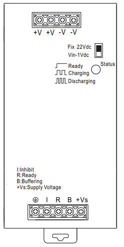
Back-up Threshold Voltage Selectable by Switch:
Option 1: Fixed mode (Switch in Fix 22Vdc)
The unit switches to buffer mode as soon as the voltage falls below 22Vdc. Option 2: Dynamic mode (Switch in Vin-1Vdc)
Unit switches to buffer mode when input voltage decreases by 1Vdc.
Note: Factory setting is fixed mode.
LED Indicator Status:
LED OFF: Capacitors are discharged.
LED ON: Capacitors are fully charged.
LED Flashing slowly (1Hz): Capacitors are getting charged.
LED Flashing quickly (10Hz): Capacitors are getting discharged.
Signal Connector:
-Inhibit,+Vs – V(I)<6Vdc: Buffer module ON; +Vs – V(I)>10Vdc: Buffer module OFF.
-Ready, Charged ready: V(R)>+Vs-2Vdc; Unready: V(R)<1Vdc. -Buffering, Buffering: V(B)>+Vs – 2Vdc; Other mode: V(B)<1Vdc.
2. Operating Diagram

3. Signal Schematics

(+Vs can connected to DBUF40 “+V” or external voltage source,Please refer to “Typical Application Notes”)
Typical Application Notes
1. General wiring diagram

2. Signals supplied from an external voltage

3. Paralleling of buffer units

Mechanical Specification

Installation Instruction

Installation Manual
Please refer to : http://www.meanwell.com/manual.html
![]()
Documents / Resources
 |
MEAN WELL DBUF40-24 DIN Rail Type Buffer Module [pdf] Owner's Manual DBUF40-24 DIN Rail Type Buffer Module, DBUF40-24, DIN Rail Type Buffer Module, Type Buffer Module, Buffer Module |